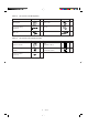
INSTALLATION INSTRUCTION 1 — Split System Heat Pump Air Conditioner — X 2 Model Combinations K Combine indoor and outdoor units only as listed below.
Important Please Read Before Starting When Installing …………………………………………………………………… This air conditioning system meets strict safety and operating standards. As the installer or service person, it is an important part of your job to install or service the system so it operates safely and efficiently. …In a Room Properly insulate any tubing run inside a room to prevent “sweating” that can cause dripping and water damage to walls and floors.
CONTENTS Page Page 3-25. Checking the Drainage IMPORTANT Please Read Before Starting 1. 2. GENERAL ................................................................... 4 3-26. Increasing the Fan Speed 4. HOW TO INSTALL THE OUTDOOR UNIT ................ 40 1-1. Tools Required for Installation (Not Supplied) 4-1. Removing the Protective Spacer for Transportation 1-2. Accessories Supplied with Unit 4-2. Installing the Outdoor Unit 1-3. Type of Copper Tube and Insulation Material 4-3.
Page 8. HOW TO INSTALL THE WEEKLY TIMER (OPTIONAL PART) ................................................... 65 8-1. Mounting Dimensions for Continuous Installation 8-2. When Using a Wall Box for Flush Mounting 8-3. Wiring Diagram 8-4. Test Run Setting 8-5. Memory Back Up Function for Power Failure Compensation 9. HOW TO INSTALL THE SYSTEM CONTROLLER (OPTIONAL PART) ................................................... 67 9-1. System Controller Installation 9-2. Electrical Wiring 9-3.
1. GENERAL CAUTION This booklet briefly outlines where and how to install the air conditioning system. Please read over the entire set of instructions for the indoor and outdoor units and make sure all accessory parts listed are with the system before beginning. 1-4. Additional Materials Required for Installation 1-1. Tools Required for Installation (Not Supplied) 1. Standard screwdriver 2. Phillips head screwdriver 3. Knife or wire stripper 4. Tape measure 5. Level 6. Sabre saw or key hole saw 7.
Table 1-1 XH (4-Way Air Discharge Semi-Concealed) Part Name Figure Q’ty Remarks 1 For determining suspension bolt pitch Flare insulator 2 For wide and narrow tubes Washer 8 For suspending indoor unit from ceiling 1 For wide tube flare nuts Hose band 2 For securing drain hose Packing 1 For drain joint Drain insulator 1 For drain joint Drain hose 1 Drain hose adaptor 1 For drain outlet Sealing putty 1 For sealing recessed portion of power supply Tube connector 1 For sizing up
Table 1-3 TH (Ceiling-Mounted) Part Name Figure Q’ty Special washer 4 For temporarily suspending indoor unit from ceiling Drain insulator 1 For drain hose joint Flare insulator T3 T5 1 Set For wide tube joints Drain hose adaptor 1 Drain hose clamp 4 Black 2 For wide tube and drain hose joint White (heat-resisting) 1 For wide flare joints Vinyl clamp 2 For ends of flare insulator Full-scale installation diagram 1 For determining suspension bolt pitch Sealing putty 1 For sealing
Table 1-6 (Accessories for the Wired Remote Controller) Part Name Figure Q’ty Part Name Figure Q’ty 1 Wired remote controller (comes with 7-7/8 in. wire) 1 Spacers 2 Machine screws M4 × 1 in. 2 Wire joints 4 Wood screws 2 X 2 K 3 Table 1-7 T (Accessories for the Wireless Remote Controller)
Table 1-8 (Accessories for the Weekly Timer) Part Name Figure Q’ty Part Name Figure Q’ty Weekly timer 1 Wood screws 2 Connecting wiring length 4 ft. 1 Spacers 2 Machine screws M4 × 1 in. 2 Clampers 2 Table 1-9 (Accessories for the System Controller) Part Name Figure Q’ty Part Name Figure Q’ty SYSTEM CONTROLLER IDENTIFICATION LABEL ALL Central Control System controller Label (Identification label) 1 ALL RCU. ZONE1 Central Control ZONE1 RCU. ZONE2 Central Control ZONE2 RCU.
1-5. Tubing Length ● Refrigerant tubing between the indoor and outdoor units should be kept as short as possible. Tubing length (L) INDOOR UNIT 1 X ● Select and decide the installation location so that the length of the refrigerant tubing will be within the limits given in Table 1-10. Elevation difference (H) OUTDOOR UNIT 2 K 0711_M_I Fig. 1-1 Table 1-10 Models Tubing Data CH2442 CH3642, CH4242 3 T Narrow tube in. (mm) 1/4 (6.35) 3/8 (9.52) Wide tube in. (mm) 3/4 (19.05) 3/4 (19.
2. SELECTING THE INSTALLATION SITE Indoor Unit Ceiling-Mounted Type AVOID: ● areas where leakage of flammable gas may be expected. Ceiling ● places where large amounts of oil mist exist. Wall ● direct sunlight. Min.10 inch ● locations near inverter lamps which may affect performance of the unit. Min.10 inch Front view NOTE The rear of the indoor unit can be installed flush against the wall. ● locations near heat sources which may affect performance of the unit.
Exhaust fan Outdoor Unit 1 Hot air AVOID: Heat source X Outdoor unit ● heat sources, exhaust fans, etc. (Fig. 2-1) ● damp, humid or uneven locations. 2 K 0591_C_I DO: Fig. 2-1 ● choose a place as cool as possible. 3 ● choose a place that is well ventilated and outside air temperature does not exceed maximum 115°F constantly. Min. 1 inch ● allow enough room around the unit for air intake/ exhaust and possible maintenance. (Fig. 2-2) Min. 1 inch Obstacle above Min. 7 ft. 4 in.
2-1. Air Discharge Chamber for Top Discharge Air discharge Install the air-discharge chamber in the field when: ● it is difficult to keep a space of minimum 2 ft. between the air-discharge outlet and the obstacle. ● the air-discharge outlet is facing the sidewalk and discharge hot air can annoy the passers-by. Refer to Fig. 2-4.
2-3. Precautions When Installing in Heavy Snow Areas (1) The platform should be higher than the maximum. snow depth. (Fig. 2-5) The two anchoring feet of the outdoor unit should be attached to the platform, and the platform should be installed beneath the air-intake side of the outdoor unit. The platform foundation must be solid and the unit must be secured with anchor bolts. When installing on a roof subject to strong wind, countermeasures must be taken to prevent the unit from being overturned.
3. HOW TO INSTALL THE INDOOR UNIT Hole-in-anchor Hole-in-plug 3-1. Suspending the Indoor Unit Concrete Insert This unit uses a drain pump. Use a carpenter’s level to check that the unit is level. 3-2. Preparation for Suspending (1) Fix the suspension bolts securely in the ceiling using the method shown in the diagrams (Figs. 3-1 and 3-2), by attaching them to the ceiling support structure, or by any other method that ensures that the unit will be securely and safely suspended.
3-3. Placing the Unit Inside the Ceiling (2) (3) When placing the unit inside the ceiling, determine the pitch of the suspension bolts using the supplied full-scale installation diagram. (Fig. 3-4) The size of the opening for the indoor unit can be confirmed by attaching the full-scale installation diagram beneath the unit. (Fig. 3-4) Tubing and wiring must be laid inside the ceiling when suspending the unit.
3-4. Installing the Drain Piping (1) 1 X Transparent part for checking drainage Prepare standard hard PVC pipe for the drain and use the supplied drain hose and hose band to prevent water leaks. The PVC pipe must be purchased separately. The transparent part allows you to check drainage. (Fig. 3-6) CAUTION (2) Packing (supplied) Tighten the hose clamps so their locking nuts face upward. (Fig. 3-6) Drain hose (supplied) Hard PVC pipe (not supplied) Drain hose adapter (supplied) 0964_X_I Fig.
3-5. Checking the Drainage After wiring and piping are completed, use the following procedure to check that the water will drain smoothly. For this, prepare a bucket and wiping cloth ready to catch and wipe up spilled water. 1 X Do not supply power to the unit until the tubing and wiring to the outdoor unit are completed. (1) Take off the tube cover and through the opening, slowly pour about 43 oz. of water into the drain pan to check drainage.
1 ■ Ceiling Panel X CAUTION Never touch or attempt to move the air direction louver by hand or you may damage the unit. Instead, use the remote control unit if you want to change the direction or air flow. 3-6. Before Installing the Ceiling Panel (1) (2) Remove the air-intake grille and air filter from the ceiling panel. (Figs. 3-13 and 3-14) (a) Remove the 2 screws on the latch of the airintake grille. (Fig.
3-7. Installing the Ceiling Panel (1) Lift the ceiling panel and position it to align the (5) panel hook with the panel catch of the indoor unit. NOTE The ceiling panel must be mounted in the correct direction. Note that the 2 catches of the panel differ in size. Confirm that the catches are correctly matched between the ceiling panel and the indoor unit body. (2) Next, check to see that the ceiling panel is properly aligned with the seamline of the ceiling.
3-9. Duct for Fresh Air Air-intake plenum CMB-GSJ80U CMB-GSJ140U ho le Type PNR-XH2442 (XH1242, XH1842, XH2442) PNR-XH3642 (XH3642, XH4242) 4ø1 /8 X ● There is a duct connection part on sideface of the indoor unit. (Fig. 3-16) ● Optional air-intake plenum (including duct connection box and flange) can be attached to the indoor unit. 2-3/8 1 For fresh air intake ø4 -1 3/3 2 2-5/32 (1) Accessories ● Check that the following parts are in the box when unpacking.
(e) Installing the ceiling panel ● Attach the ceiling panel to the chamber. Drawing the panel downwards sets the panel in position temporarily with the panel catch (at 2 locations). ● Remove the socket cover of the air-intake plenum and pass the 8P sockets through it. (Fix the panel lead wire to chamber side clamper.) (Fig. 3-17) ● Connect the 8P socket (electrical component box side) to the 8P socket (ceiling panel side) of the indoor unit electrical component box. ● Reattach the socket cover.
■ Wall-Mounted Type (KH Type) 3-10. Removing the Wall Fixture from the Unit Wall fixture KH2442 2 K Remove and discard the set screws and take off the wall fixture. (Fig. 3-19) Set screws only for transportation 1390_T_I 3-11. Selecting and Making a Hole Fig. 3-19 KH2442 (1) (2) F u ll -s c a le in s ta ll a ti o n d ia g ra m Before drilling a hole, check that there are no studs or pipes behind the determined location.
KH3642 One hole is required for the air conditioner tubing, and may be either on the left or right side. (Also see section 3-14. Preparing the Indoor Side Tubing.) (1) Determine if the hole is to be drilled at the left or right hole location. (3) Before drilling a hole, check that there are no studs or pipes behind the determined location. CAUTION (5) (6) Full scale installation diagram Tape the full-scale installation diagram on the wall at the location selected.
3-12. Installing the Wall Fixture onto Wooden or Gypsum Wall wall fixture KH2442 Confirm that the wall is strong enough to support the unit. a) If the Wall is Wooden 2 (1) K Attach the wall fixture to the wall with the 9 screws provided. (Fig. 3-28) If you are not able to line up the holes in the wall fixture with the beam locations marked on the wall, use rawl plugs or toggle bolts to go through the holes on the panel or drill 13/64 in. dia.
3-13. Removing the Casing to Install the Indoor Unit KH2442 How to Remove the Casing (1) Remove the plastic cover. (Fig. 3-31) (2) Remove the clamp for the wiring connector. (Fig. 3-32) (3) Disconnect the wiring connector. (Fig. 3-33) (4) Set the flap in the horizontal position. (Fig. 3-34) (5) Remove the 3 screws. (Fig. 3-34) (6) Remove the casing. (Fig. 3-34) Plastic cover 2 K Screw 0945_T_I Fig.
3-14. Preparing the Indoor Side Tubing Left tubing Right-rear tubing (Recommended) Left-rear tubing KH2442 Tubing can be extended in 4 directions as shown in Fig. 3-35. Right tubing Arrangement for Left Tubing 2 K (a) Fig. 3-35 0949_T_I Cut out the left tubing outlet. (Fig. 3-36) Arrangement for Right Tubing (a) Cut out the right tubing outlet using a hacksaw. (Fig. 3-37) Right tubing outlet Left tubing Arrangement for Left-rear and Right-rear Tubing.
3-15. Wiring Instructions General Precautions on Wiring (1) Before wiring, confirm the rated voltage of the unit as shown on its name plate, then carry out the wiring closely following the wiring diagram. (2) Provide a power outlet to be used exclusively for each unit a power supply disconnect and circuit breaker for overcurrent protection should be provided in the exclusive line. (3) To prevent possible hazards from insulation failure, the unit must be grounded.
3-16. Wiring Instructions for Inter-Unit Connections (a) 2 K (b) (c) (d) (e) KH2442 Insert the inter-unit wiring (according to local codes) into the through-the-wall PVC pipe. Run the wiring toward the indoor side allowing approx. 5". to extend from the wall face. (Fig. 3-44) Never fix the wiring by any means before the indoor CAUTION unit is fully seated on the rear panel. Remove the side cover and the metallic cover. (Fig. 3-45 or 3-46, depending on model.
Cover 3-17. Shaping the Tubing Refrigerant tubing KH2442 (1) Shape the refrigerant tubing so that it can easily go into the hole. (Fig. 3-47) (2) Push the wiring, refrigerant tubing and drain hose through the hole in the wall. Adjust the indoor unit so it is securely seated on the wall fixture. (3) (4) (5) Inter-unit wiring Drain hose 2 0954_T_I K Fig.
3-18. Installing the Drain Hose 2 K (a) The drain hose should be slanted downward on the outdoor side. (Fig. 3-53) (b) Never form a trap in the course of the hose. (c) If the drain hose will run in the room, insulate* the hose so that chilled condensation will not damage furniture or floors. (Fig. 3-54) Slant Indoor unit Drain hose 0957_T_I Fig. 3-53 * Foamed polyethylene or its equivalent is recommended.
■ Ceiling-Mounted Type (TH Type) Front face 3-19. Suspending the Indoor Unit (1) Place the full-scale diagram (supplied) on the ceiling at the spot where you want to install the indoor unit. Use a pencil to mark the drill holes. (Fig. 3-55). Rear Full-scale diagram 0035_T_I NOTE Fig. 3-55 Since the diagram is made of paper, it may shrink or stretch slightly because of high temperature or humidity. For this reason, before drilling the holes maintain the correct dimensions between the markings.
3 T (7) Hinge Latch de Sli (6) Before suspending the indoor unit, remove the 2 screws on the latch of the air-intake grilles, open the grilles, and remove them by pushing the claws of the hinges as shown in Fig. 3-59. Then remove both side panels sliding them along the unit toward the front after removing the two screws which fix them. (Fig. 3-60) Preparation for suspending the indoor unit. The suspension method varies depending on whether the unit is next to the ceiling or not. (Fig.
(b) Lift the indoor unit, and place it on the washers through the notches, so as to fix it in place. (Fig. 3-64) (c) Tighten the two hexagonal nuts on each suspension bolt to suspend the indoor unit as shown in Fig. 3-65. NOTE 3 A ceiling surface is not always level. Please confirm that the indoor unit is evenly suspended. For the installation to be correct, leave a clearance of about 3/8 in.
3-20. Duct for Fresh Air 3 T Duct connection port (Knock-out hole) There is a duct connection port (knock-out hole) at the right-rear on the Panel Top of the indoor unit for drawing in fresh air. If it is necessary to draw in fresh air, remove the cover by knocking out and connect the duct to the indoor unit through the connection port. (Fig.
■ Concealed-Duct Type ( UH Type) ● This air conditioner is usually installed above the ceiling so that the indoor unit and ducts are not visible. Only the air intake and air outlet ports are visible from below. min. 9-27/32 ● It is recommended that space is provided (17-23/32 × 17-23/32 in.) for checking and servicing the electrical system. ● Fig. 3-73 and Table 3-4 show the detailed dimensions of the indoor unit.
3-23. Suspending the Indoor Unit Hole-in-anchor Hole-in-plug Depending on the ceiling type: Concrete Insert • Insert suspension bolts as shown in Fig. 3-74 or • Use existing ceiling supports or construct a suitable support as shown in Fig. 3-75. Suspension bolt (M10 or 3/8") (field supply) It is important that you use extreme care in supporting the indoor unit inside the ceiling. Ensure that the ceiling is strong enough to support the weight of the unit.
● Fig. 3-78 shows an example of installation. Bolt anchor Air outlet duct Suspension bolt Air-intake duct Air-outlet grille Ceiling material Indoor unit Air-intake grille 4 0785_U_I U Fig. 3-78 3-24. Installing the Drain Piping (1) Transparent part for checking drainage Prepare a standard hard PVC pipe for the drain and use the supplied hose band to prevent water leaks. The PVC pipe must be purchased separately.
● Do not install an air Air bleeder bleeder as this may cause water to spray CAUTION from the drain pipe outlet. (Fig. 3-81) ● If it is necessary to increase the height of the drain pipe, the section directly after the connection port can be raised a maximum of 19-11/16 in. Do not raise it any higher than 19-11/16 in., as this could result in water leaks. (Fig. 3-82) Not good 1593_U_I Fig. 3-81 11-13/16 in. or less Good 19-11/16 in.
3-26. Increasing the Fan Speed If external static pressure is too great (due to long extension of ducts, for example), the air flow volume may drop too low at each air outlet. This problem may be solved by increasing the fan speed using the following procedure: Booster cable Fan motor socket (At shipment) Remove 4 screws on the electrical component box and remove the cover plate. (Booster cable installed) 0491_M_I Fig. 3-85 (2) Disconnect the fan motor sockets in the box.
4. HOW TO INSTALL THE OUTDOOR UNIT 4-1. Removing the Protective Spacer for Transportation Compressor Remove the packing skid from the bottom of unit and then remove the plastic spacer used to secure the compressor during transportation. (Fig. 4-1) Place the unit on a level concrete pad, block or equal and anchor. Refer to Section 2. “Selecting the Installation Site”. Packing skid Plastic spacer 0496_C_I Fig.
5. ELECTRICAL WIRING 5-1. General Precautions on Wiring (1) Before wiring, confirm the rated voltage of the unit as shown on its nameplate, then carry out the wiring closely following the wiring diagram. (2) Provide a power outlet to be used exclusively for each unit, and a power supply disconnect and circuit breaker for overcurrent protection should be provided in the exclusive line. (3) To prevent possible hazards from insulation failure, the unit must be grounded.
5-3. Wiring System Diagrams (1) Basic wiring diagram for standard control Indoor Unit Outdoor Unit B Inter-unit power wiring Single phase 230/208V Inter-unit control wiring (Low voltage) 1 1 1 1 2 2 G G Ground U1 U1 U2 U2 1 R.C. Address on the PCB: 0 (S2, BLK) (0: Factory shipped state) 0 C L1 L1 L2 L2 G 2 2 2 D Remote controller (Option) *Remote controller wirings are wire joint connection.
(2) Basic wiring diagram for group control This diagram shows when several units (max. 8) are controlled by a remote controller. In this case, a remote controller can be connected at any indoor unit. Indoor Unit Outdoor Unit B Inter-unit power wiring single phase 230/208V 1 1 2 2 G *1 R.C.
Loose wiring may cause the terminal to overheat or result in unit malfunction. A fire hazard may also exist. Therefore, ensure that all wiring is tightly connected. Strip 3/8 in. Stranded wire When connecting each power wire to the corresponding terminal, follow the instructions on “How to connect wiring to the terminal” and fasten the wire securely with the fixing screw of the terminal plate. Ring pressure terminal 1106_M_I Fig. 5-1 5-4.
6. HOW TO INSTALL THE WIRED REMOTE CONTROLLER (OPTIONAL PART) 6-1. Installation site selection ● Install the remote controller at a height of between 3–5 ft. above the floor. ● Do not install the remote controller in a place where it will be exposed to direct sunlight or near a window or other place where it will be exposed to the outside air. ● Be sure to install the remote controller vertically, such as on a wall.
6-2. Wired Remote Controller Installation 6 RC (WD) ● Do not supply power to the unit or try to operate it until the tubing and wiring to the outdoor unit is completed. ● Do not twist the control wiring with the power CAUTION wiring or run it in the same metal conduit, because this may cause malfunction. ● Install the remote controller away from sources of electrical noise. ● Install a noise filter or take other appropriate action if electrical noise affects the power supply circuit of the unit.
6-3. Basic Wiring Diagram CAUTION Install wiring correctly ● Use shielded wires for inter-unit control wiring and (incorrect wiring will damage ground the shield on both sides. (Fig. 6-5) the equipment). Otherwise misoperation because of noise may occur. Shielded wire ground ground 0797_M_I Group control Connection wiring for group control 1 2 Standard remote control Fig. 6-5 Multiple remote control 1 2 1 2 1 2 1 2 Indoor unit No. 3 1 2 1 2 Indoor unit No.
6-4. Wiring System Diagram for Group Control This diagram shows when several units (maximum of 8) are controlled by a remote controller (master unit). In this case, a remote controller can be connected at any indoor unit. Remote controller Wiring procedure Connection wiring for group control 1 2 Wire according to the left diagram: ● Address setting is executed automatically when the outdoor unit is turned on. Wire joint 1 2 1 2 1 2 1 2 Indoor unit No. 1 Indoor unit No. 2 Indoor unit No.
6-5. Wiring System Diagram for Multiple Remote Control ■ When Installing Multiple Remote Controllers This multiple remote controller system is used for operating the unit(s) at different positions. (A maximum of 2 remote controllers can be installed.) ● Setting method Remote controller To execute this control, make the setting according to the following procedure. (1) Of the two installed remote controllers, make one the main remote controller (factory-shipped state).
6-7. Explanation of Alarm Messages Possible Cause of Malfunction • Serial communication errors • Mis-setting Remote controller is detecting error signal from indoor unit. Error in receiving serial communications signal. Error in transmitting serial communications signal. Alarm message E1 E2 • Indoor unit is detecting error signal from the remote controller. (No serial communications signal) E3 Indoor unit is detecting error signal from outdoor unit. Error in receiving serial communications signal.
Alarm message Possible Cause of Malfunction Thermistor failure Indoor thermistor is either open or damaged. Outdoor thermistor is either open or damaged. Indoor coil temp. (E1 = TH1) cannot be detected. F1 Indoor coil temp. (E2 = TH2) cannot be detected. F2 Indoor coil temp. (E3 = TH3) cannot be detected. F3 Indoor room (air-intake) temp. can not be detected. F10 Discharge gas temp. (comp. = TH0A) cannot be detected. F4 Outdoor coil gas temp. (C2 = TH0C) cannot be detected.
7. HOW TO INSTALL THE WIRELESS REMOTE CONTROLLER (OPTIONAL PART) Important When using this air conditioner (ECO multi system air conditioner) with the wireless remote controller it may sometimes be impossible to change the operation modes while other indoor unit is running. ● When this happens, a double beep tone sounds, the (operation lamp) lights up, and the (Timer lamp) and (Standby lamp) blink alternately. Operation is the same even during (AUTO mode) automatic cooling or heating.
7-2. Room Temperature Sensor Setting The room temperature sensors are built into the indoor unit and the wireless remote controller. Either of these room temperature sensors can operate. The system is shipped from the factory set to the indoor unit sensor. To switch to the remote controller sensor, press the sensor switching button located inside the remote controller cover and check that A/C SENSOR on the LCD display panel goes out.
1 X ■ 4-Way Air Discharge Semi-concealed Type (XH Type) Air intake grille Mark section (indicator section) 7-5. Indicator section Installation ● Remove the ceiling panel and indicator cover and install the indicator section. (1) (2) (3) (4) (5) (6) Remove the ceiling panel. Remove the corner cover behind the mark section. (3 screws) Remove the mark section inside the ceiling panel. (2 screws) Install the indicator section in the location where the mark section was attached.
■ Ceiling Mounted Type (TH Type) 7-7. Indicator Section Installation Remove the side panel to install the indicator section. (Fig. 7-8) (1) (2) (3) (4) (5) (6) (7) Indicator section Indicator section Cover B (Not used when the indicator section is installed.) Remove the side panel. Open the air intake grille, remove the screw at one place and then remove the side panel by sliding it toward the front (arrow direction). Remove cover A and cover B.
7-9. Electrical Wiring Signal receving unit Indoor PCB 1 WL 2 W3 Indicator section (4.3 ft.) CN1 Operating controller W2 CN2 (0.7 ft.) CN1 BLU W1 (4.3 ft.) YEL PNK WHT RED BLK GRY BLK BLU YEL PNK RED GRY BLK Relay connector 2035_M_I Fig. 7-10 Connection method (1) Connect W1 to the indoor PCB WL connector. (2) Connect W3 from the indicator section with W2 from the operating controller using the relay connector. 7-10. Test Run Switch Test run switch is located at operating control unit.
7-11. Misoperation Alarm Indicators Alarm indicator lamps on the indoor unit indicate the error cause when the air conditioner fails to operate upon being switched on. The possible alarm indications are given in Table 7-1. Fig.7-12 shows the location of the alarm lamps on the indoor unit. (See Table 7-1, Fig. 7-12) Table 7-1 Alarm (OPERATION lamp) * (TIMER lamp) Cause of Trouble (STANDBY lamp) O ● ● ● ● O O ● O O ● O ● O O ● O ● O O O S.C.
CAUTION ● If the signal receiving unit is installed near rapidstart type or inverter type fluorescent lamp (neither one having glow lamps), it may be impossible to receive signals from the wireless remote controller. To avoid signal interference from fluorescent lamps, install the receiving unit at least 6.6 ft. away from the lamps and install at a location where wireless remote controller signals can be received when the fluorescent lamps are on. 7-12.
● When using the signal receiving unit on a wall with the front exposed, choose a wall surface that the signal receiving unit can be mounted on. (1) (2) (3) (4) (5) (6) (7) (8) Clamper (supplied) About 3/32-1/8 in. Run the remote control cable through a notch on the upper case. Insert a flat tip (minus) screwdriver into the slot on the lower side of the signal receiving unit and pry off the back case as shown in Fig. 7-14.
7-13. Electrical Wiring Make correct wiring without any mistakes (incorrect wiring will damage the equipment). CAUTION ● Recommended wire diameter and allowable length for signal receiving unit wiring and its branch wiring: AWG #18, MAX 1,300 ft. Terminal board for indoor unit remote controller wiring 1 2 WHT BLK 1 2 Signal receiving unit Wire from signal receiving unit Connection Signal receiving unit wiring (field supply) 2010_M_I Wire joint (2 pcs.
7-15. Misoperation Alarm Indicators A blinking lamp for other than the signal receiving unit filter shows that a problem has occurred in the unit so make an inspection. (Refer to servicing information in the service manual, etc.) Also, if wired remote controller and dedicated service check lines (854-9-9536044-97: service use) are available, then detailed error information can be obtained by connecting to the service connector as shown in the drawing.
7-16. Basic Wiring Diagram CAUTION Install wiring correctly ● Use shielded wires for inter-unit control wiring and (incorrect wiring will damage ground the shield on both sides. (Fig. 7-25) the equipment). Otherwise misoperation because of noise may occur. Shielded wire ground ground 0797_M_I Group control Connection wiring for group control 1 2 Terminal 3P 1 2 Indoor unit No. 1 1 2 1 2 Indoor unit No. 2 1 2 Standard remote control Fig.
7-17. Wiring System Diagram for Group Control This diagram shows when several units (maximum of 8) are controlled by a signal receiving unit (master unit). In this case, a signal receiving unit can be connected at any indoor unit. Signal receiving unit 1 2 Wire joint (2 wires) Wiring procedure Connection wiring for group control 1 2 1 2 1 2 1 2 Indoor unit No. 1 Indoor unit No. 2 Indoor unit No. 3 Indoor unit No.
7-18. Wiring System Diagram for Multiple ■ When Installing Multiple This multiple system is used for operating the unit(s) at different positions. (A maximum of 2 signal receiving unit can be installed.) ● Setting method To execute this control, make the setting according to the following procedure. (1) Of the two installed signal receiving unit, make one the main signal receiving unit (factoryshipped state).
8. HOW TO INSTALL THE WEEKLY TIMER (OPTIONAL PART) Spacer Do not supply power to the unit or try to operate it until the tubing and wiring to the outdoor unit is completed. Wall 3-17/32 in. or more 4-29/32 in. or more 8-1. Mounting Dimensions for Continuous Installation ● For vertical continuous installation, the space between the weekly timer and the remote controller must be 1 in. or more.
8-4. Test Run Setting 8-3. Wiring Diagram (For wiring, always use the supplied wires) Timer terminal Weekly timer 1 2 3 4 1 2 3 4 1 2 3 4 Timer terminal Remote 1 controller 2 or 3 System 4 controller FORCED OPR. switch 0806_M_I ON OFF Connection wiring (supplied) ● After installation, check the output state of the weekly timer with the “FORCED OPR.” switch (OFF to ON) located on the rear side of its PCB. After confirming normal operation, turn the “FORCED OPR.” switch back to OFF without fail.
9. HOW TO INSTALL THE SYSTEM CONTROLLER (OPTIONAL PART) Do not supply power to the unit or try to operate it until the tubing and wiring to the outdoor unit is completed. 9-1. System Controller Installation CAUTION Switch box (no cover) ● Do not twist the control wiring with the power wiring or run it in the same metal conduit, because this may cause malfunction. M4 × 1-3/16 in. Screws (2) Back case ● Install the system controller away from sources of electrical noise.
9-2. Electrical Wiring How to connect electrical wiring Indoor unit PCB (1) (2) Connect B1, B2 to indoor PCB CRV connector using accessary 2P connector. (*No polarity) Total wire legth is less than 985 ft. and size is AWG#18. B1 Connect B5, B6 to indoor unit 2P terminal base. (*No polarity). Wire size is AWG#18.
9-3. Address Switch Setting SW1 SW1 ON Main/sub selection switch OFF: System controller operates as main controller. ON: System controller operates as sub-controller. 1 2 3 4 5 6 7 8 OFF ALL/ZONE mode selection switch ALL mode: All indoor units can be controlled by system controller ZONE 1, 2, 3, 4 mode: Indoor units in one of zone 1, 2, 3, or 4 can be controlled by system controller. All indoor units cannot be set.
SW2 SW2 Weekly timer input switches. System controller operation can be set when weekly timer activates (ON/OFF). ON 1 6 Ditto All OFF and all indoor units to be 2*2 3 4 5 6 7 8 OFF Switch No.
9-4. Mode Setting Central control mode According to function of each system controller, set SW1 as Fig. 9-5. (1) 2 3 4 5 6 Central control/Remote control mode ● Central control mode System controller is used as central control equipment. Individual setting by remote controller can be inhibitted by system controller 2 3 4 5 6 ON OFF ON OFF ALL central control ALL remote control Inter-unit control wiring 2 3 4 5 6 ● Remote control mode System controller is used as remote controller.
9-5. How to Perform Zone Registration To operate the system controller properly, zone registration is required after finishing the test run (and after setting all indoor unit addresses) using one of the following methods.
(a) Zone registration using the remote controller (RCS-SH80UG) (Determination of central address) ● In this case, after confirming which indoor unit is connected to the remote controller and that the air conditioner in the OFF state, you set the central addresses one at a time. ● If the system has no remote controller, connect a remote controller to the system temporarily. Then follow this procedure. NOTE The indoor unit address must already have been set before performing zone registration.
(b) Zone registration using the system controller (SHA-KC640G) ● In this case, you set all central addresses by system controller at once manually. ZONE ZONE (1) and ZONE buttons at the same Press the time for more than 4 seconds. and CODE No. C1 will flash. (2) After confirming that CODE No. C1 is displayed, press the button. Once in this mode, a change takes place as Fig. 9-8. (3) (4) 2 3 4 6 9 Selected group No. if no data is registered. If data is registered the unit No. is displayed.
(c) Automatic zone registration using the system controller (SHA-KC64UG) (1) Press the and ZONE buttons at the same time for more than 4 seconds. and CODE No. C1 will flash. (2) Select CODE. No. C2 by pressing ( ) button and press the ZONE ZONE 1 2 3 4 6 9 and button. C2 changes from flashing to ON state and automatic zone registration will start. GROUP (3) Registered GROUP No. will be disappeared all.
■ How to check overlapping of central address No. (1) (2) Press the and ZONE buttons at the same time for more than 4 seconds. and CODE No. C1 will flash. Select CODE. No. C3 by pressing ( ) button and press the ZONE ZONE 1 2 3 4 , button. C3 changes from flashing to ON state and will flash. Then auto. overlap checking will start . (3) GROUP SELECT If C3 changes from ON to flashing and stops flashing and disappears, there is no overlapping.
■ ZONE registration table ZONE GROUP 1 2 Indoor unit Central address address (UNIT No.) Unit location ZONE GROUP Indoor unit Central address address (UNIT No.
Name Input/output Terminal ON/OFF output Alarm output Potential tree A contact, static (relay output) Contact capacity DC 30V, 0.5A All ON input All OFF input Pulse (photo compler input) Equipment ON/OFF Terminal Example Input/output Wire length: less than 330 ft. CPEV AWG#16 Digital input Status output System controller Alarm Output common ALL ON (+) CPEV AWG#16 CX Pulse width: +24 more than 984 ft./sec. Wire length: less than 330 ft.
10. HOW TO PROCESS TUBING Deburring The narrow tubing side is connected by flare nut, and the wide tubing side is connected by brazing. Before After 10-1. Use of the Flaring Method Many of the conventional split system air conditioners employ the flaring method to connect refrigerant tubes which run between indoor and outdoor units. In this method, the copper tubes are flared at each end and connected with flare nuts. 10-2.
10-4. Precautions during Brazing Torque wrench ● Replace air inside the tube with nitrogen gas to prevent copper oxide film from forming during the brazing process. ● Do not allow the tubing to get too hot during the brazing process. The nitrogen gas inside the tubing may overheat, causing refrigerant system valves to become damaged. Therefore allow the tubing to cool between brazings. Spanner Indoor unit Outdoor unit 0131_C_I Fig. 10-6 Insulation Thickness: Min. 5/16 in. 10-5.
10-7. Taping the Tubes (1) At this time, the refrigerant tubes (and electrical wiring if local codes permit) should be taped with armoring tape in 1 bundle. To prevent the condensation from overflowing the drain pan, keep the drain hose separate from the refrigerant tubing. (2) Wrap the armoring tape from the bottom of the outdoor unit to the top of the tubing where it enters the wall. As you wrap the tubing, overlap half of each previous tape turn. (Fig.
11. AIR PURGING Manifold valve Air and moisture in the refrigerant system may have undesirable effects as indicated below.
CAUTION To avoid nitrogen entering the refrigerant system in a liquid state, do not use the nitrogen cylinder up side down. Use the cylinder in a vertical standing position. (Refer to the previous page.) (4) Do a leak test of all joints of the tubing (both indoor and outdoor) and both wide and narrow service valves. Bubbles indicate a leak. Wipe off the soap with a clean cloth after the leak tests.
Charging additional refrigerant ● Charge additional refrigerant (calculated from the narrow tube length as shown in Sec. 1-5) using the wide tube service valve with the system in cooling operating mode. (Fig. 11-5) Wide tube Outdoor unit ● Use a balance to measure the refrigerant accurately. 165 ft. 1396_M_I Fig. 11-5 Finishing the job (1) With a hex wrench, turn the narrow tube service valve stem counterclockwise to fully open the valve. (Fig.
12. TEST RUN 12-1. Preparing for Test Run ON ● Before attempting to start the air conditioner, check the following: (1) All loose matter is removed from the cabinet especially steel filings, bits of wire, and clips. (2) The control wiring is correctly connected and all electrical connections are tight. (3) (Power must be turned ON at least 5 hours before attempting test run) Power mains switch 0765_C_I The protective spacers for the compressor used for transportation have been removed.
12-2. PCB Setting ● Setting of outdoor control PCB (A) Standard control (single outdoor unit) In case of single outdoor unit installation, even if in case of twin, triple or quartet type (2, 3 or 4 indoor units), no setting necessary. Keep factory shipment state (R.C. address is set in “0”). In this case, auto. address operation takes place automatically for the first time when the power is switched on. This takes about a few minutes.
12-3. R.C. Address Setting Method Outdoor unit R.C. address setting method In case of group control or central control, set the R.C. address to 1, 2, 3, ... according to the No. of outdoor units. Outdoor control PCB CN006 (2P Black) Refrigerant circuit address (factory setting = 0) Refrigerant circuit address (black) 0 : S2 Refrigerant circuit address (2P DIP switch, green or Blue) 10 20 position position ON ON side A.
12-4. Automatic Address Setting Method — For group control and central control with multiple outdoor units — Carry out automatic address setting with the remote controller. (1) All auto. address operation 1 Press the and ( ) buttons at the same time for more than 4 seconds. 2 button after confirming the Press the CODE No. AA (CODE No. AA: All Auto. address operation). After addresses are automatically set in order for the outdoor units from No. 1 to No. 30, the system returns to the normal stopped state.
12-6. Test Run Procedure Start Multiple remote control? Yes Turn on RCU address SW of sub remote control unit No Recheck the test items before test operation. (Sec. 12-7) Check the indoor and outdoor unit combination (wiring). (Sec. 5-3) Yes Single type? (One indoor unit and one remote controller for one outdoor unit) Multiple indoor units for one outdoor units? No Turn on power supply for indoor units side first Then turn on power supply for outdoor unit side.
12-7. Items to Check Prior to Test Run (1) Turn on the power supply switch more than 5 hours before in order to charge the crank case heater. (2) Fully open the outdoor service valve after making the leak inspection of field connected tubing, vacuuming, and gas charging if necessary. (3) Check the capacity code setting. * The factory setting is as shown in the table. Double check it. * The capacity code is set by S4 (green or blue, 4P DIP switch) on outdoor control PCB.
12-8. The Main Alarms of Mis-wiring & Mis-setting Remote controller • In case of individual remote control display Cause In case of group control In case of multiple remote control Nothing • Remote controller not properly connected. displayed • Power supply not ON. E1 • Remote controller not properly connected. E4 • Wiring connection fault of indoor/outdoor units • Wiring connection fault of some indoor/outdoor units inside the group • Power supply of outdoor unit not ON.
■ Basic Functions of the Service Valves Narrow Tube Service Valve (3-Way) Action CLOSED Wide Tube Service Valve (Ball Valve) CLOSED O-ring Stem Shipping and air purging 0549_C_I 0546_C_I Fully OPEN Fully OPEN Operating and test running the air conditioner 0550_C_I 0547_C_I Half OPEN Fully OPEN Measuring pressure and gas charging 0550_C_I 0548_C_I Narrow tube service valve O-ring Valve cap Stem O-ring Wide tube service valve Valve cap Stem Service port (B) 0554_C_I 0989_C_I 2-Way Valve C
13. PUMP DOWN Pump down means collecting all refrigerant gas in the system back into the outdoor unit without losing ant of the gas. Pump down is used when the unit is to be moved or before servicing the refrigerant circuit. Pump down procedure CAUTION Be sure to carry out pump down with the unit in cooling mode. (1) Connect the low pressure side (wide tube valve service port) charging hose of the manifold valve to the service port (B) on the wide tube service valve.