COVER1.fm 1 ページ 2002年9月6日 金曜日 午後6時34分 VCC-4115P INSTRUCTION MANUAL BEDIENUNGSANLEITUNG MANUEL D’INSTRUCTIONS COLOUR CCD camera CCD-Farbkamera Caméra CCD COULEUR CCD About this manual A propos de ce manuel Before installing and using the camera, please read this manual carefully. Be sure to keep it handy for later reference. Avant d’installer et d’utiliser la caméra, veuillez lire ce manuel attentivement. Gardez-le à portée de main pour toute référence ultérieure.
vcc4115p(gb).fm 1 ページ 2002年9月5日 木曜日 午後3時59分 Depending on the conditions of use, installation and environment, please be sure to make the appropriate settings and adjustments. If you need help with installation and/or settings, please consult your dealer. CONTENTS PRECAUTIONS .................................................. 2 PARTS NAMES .................................................. 3 MOUNTING THE LENS ...................................... 5 CONNECTIONS..........................................
vcc4115p(gb).fm 2 ページ 2002年9月5日 木曜日 午後3時59分 PRECAUTIONS ■ In case of problem Do not use the camera if smoke or a strange odour comes from the unit, or if it seems not to function correctly. Disconnect the power cord immediately, and consult your dealer (or a Sanyo Authorized Service Centre). ■ Do not open or modify Do not open the cabinet, as it may be dangerous and cause damage to the unit. For internal settings and repairs, consult your dealer (or a Sanyo Authorized Service Centre).
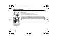
vcc4115p(gb).fm 3 ページ 2002年9月5日 木曜日 午後3時59分 PARTS NAMES 1 Flange-back lock screw (LOCK) 2 Flange-back adjustment dial 3 Lens mount cap 2 1 3 4 The cap is installed to protect the lens mount section. Remove the lens mount cap before installing a lens (sold separately). 4 Camera installation bracket The bracket can be fixed at the top or bottom of the camera. When fixing the bracket, be sure to use the longer screws and install the shorter screws on the opposite side to seal the openings.
vcc4115p(gb).fm 4 ページ 2002年9月5日 木曜日 午後3時59分 PARTS NAMES 9 5 6 7 5 6 7 8 9 Camera setup section White balance adjustment volume (R or B) Line phase adjustment volume (PHASE) Lens iris adjustment volume Lens iris output connector (LENS) This 4-pin connector is used to send the DC control signal and power supply to an auto-iris type lens. F Video output connector (VIDEO OUT: BNC type) 8 Connect this connector to a device such as a VCR or monitor with a VIDEO IN connector.
vcc4115p(gb).fm 5 ページ 2002年9月5日 木曜日 午後3時59分 MOUNTING THE LENS Please use a DC type auto-iris lens (sold separately). 1 Check the lens mount Do not use a lens if the length “L” is more than 5 mm. That may damage the camera and prevent proper installation. C mount type lens L 2 1 2 3 2 CS mount type lens 3 Remove the lens mount cap from the camera. Install the auto-iris lens. CS mount type lens Carefully align the lens mount with the camera opening, then turn the lens slowly to install it.
vcc4115p(gb).fm 6 ページ 2002年9月6日 金曜日 午後5時36分 MOUNTING THE LENS ■ Pin layout 2 1 4 3 1 2 3 4 ■ Flange-back adjustment If the pick-up surface is not correctly positioned with relation to the lens focal point, the picture will be out of focus (in particular when using auto-iris power zoom lenses, sold separately). If that is the case, adjust the flange-back position as described below.
vcc4115p(gb).fm 7 ページ 2002年9月5日 木曜日 午後4時0分 CONNECTIONS 1 24 V AC connection (A) Figure 1 12 V DC connection GND AC24V GND AC24V DC12V DC12V Figure 2 (Video signal connections) : VIDEO IN : VIDEO OUT Basic connection for monitoring or recording The peripheral devices (VCR, monitor, lens, etc.), AC adaptor and cables are sold separately. 1 Make the video signal connection between the camera and the monitor or time lapse VCR. 2 Connect the power supply.
vcc4115p(gb).fm 8 ページ 2002年9月9日 月曜日 午前11時53分 SETTINGS ■ Camera setup section No.
vcc4115p(gb).fm 9 ページ 2002年9月9日 月曜日 午前11時53分 SETTINGS ■ Iris function setting 1 This should normally be set to the down (AI) position. Use a manual or fixed iris lens and set the lens aperture to the shortest F stop. Set the switch 1 to the up (EI) position. EI When using an auto-iris lens (for indoor/ outdoor use) Set the switch 1 to the down (AI) position.
vcc4115p(gb).fm 10 ページ 2002年9月5日 木曜日 午後5時58分 SETTINGS ■ Backlight compensation setting 3 4 This camera has two different backlight correction functions: multi-spot photometry (MULTI) and center focus photometry (CENT). The normal setting (switch 3 and 4) is the down position, but you can change the switch 3 or 4 setting in accordance with the backlight conditions.
vcc4115p(gb).fm 11 ページ 2002年9月5日 木曜日 午後4時0分 SETTINGS ■ White balance adjustment 5 ■ Line phase adjustment 6 Normally the switch 5 is set to the down (ATW: auto white balance) position and the white balance is adjusted automatically. If a manual white balance adjustment is necessary, follow the steps below. Set the switch 5 to the up (MANU) position, then adjust the colour. • Turn R to set the red ratio and/or B to set the blue ratio.
vcc4115p(gb).fm 12 ページ 2002年9月5日 木曜日 午後4時0分 SETTINGS ■ Lens iris adjustment 7 If using a DC type auto-iris lens, you will need to set the LEVEL volume when shooting in the conditions described below. L H LEVEL L (counterclockwise): To decrease the contrast H (clockwise): To increase the contrast • If shooting simultaneously in a dark room and through a bright window. • If the subject background is extremely bright or dark. • If the brightness of the picture on the monitor is not correct.
vcc4115p(gb).fm 13 ページ 2002年9月5日 木曜日 午後4時0分 TROUBLESHOOTING Before taking the camera for repairs, please check below to make sure that the camera is used correctly. If it still does not perform correctly, please consult your dealer or a Sanyo Authorized Service Centre.
vcc4115p(gb).fm 14 ページ 2002年9月9日 月曜日 午前11時54分 SPECIFICATIONS ■ Camera: Scanning system : PAL standard (625 TV lines, 25 frames/sec.) Interlace : PLL 2:1 interlace Image device : 1/4 inch solid state image device CCD Picture elements : 537 (H) x 597 (V) Effective picture elements : 500 (H) x 582 (V) Synchronizing system : Internal sync, Line lock manually switchable Resolution : 350 TV lines horizontally, 400 TV lines vertically Video output level : 1.
vcc4115p(gb).fm 15 ページ 2002年9月5日 木曜日 午後4時0分 SPECIFICATIONS ■ Dimensions 108 1.4 56 99 45 10.7 16 25.8 M6 Features and specifications are subject to change without prior notice or obligations.