L53D4/US GB 1998, 3, 10 INSTRUCTION MANUAL COLOR CCD CAMERA About this manual • Before installing and using the camera, please read this manual carefully. Be sure to keep it handy for later reference.
L53D4/US GB 1998, 3, 10 SANYO INDUSTRIAL VIDEO COLOR VIDEO CAMERA LIMITED WARRANTY OBLIGATIONS In order to obtain warranty service, the product must be delivered to and picked up from an Authorized Sanyo Service Center at the user’s expense, unless specifically stated otherwise in this warranty.
L53D4/US GB 1998, 3, 10 INFORMATION TO USER Safety Guard THIS SYMBOL INDICATES THAT THERE ARE IMPORTANT OPERATING AND MAINTENANCE INSTRUCTIONS IN THE LITERATURE ACCOMPANYING THIS UNIT. WARNING: TO PREVENT THE RISK OF FIRE OR ELECTRIC SHOCK , DO NOT EXPOSE THIS APPLIANCE TO RAIN OR MOISTURE. For the customers in Canada This Class B digital apparatus complies with Canadian ICES-003. Pour la clientèle canadienne Cet appareil numerique de la Classe B est conforme a la norme NMB-003 du Canada.
L53D4/US GB 1998, 3, 10 CONTENTS FEATURES PRECAUTIONS . . . . . . . . . . . . . . . . . . . . . . . . . . . . . . . . . . . . . . . . . . . 3 • Built-in interline transfer method 1/3" CCD, approx. 410,000 PARTS NAMES AND FUNCTIONS . . . . . . . . . . . . . . . . . . . . . . . . . . . . 4 PREPARATIONS AND CONNECTIONS . . . . . . . . . . . . . . . . . . . . . . . . .
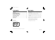
L53D4/US GB 1998, 3, 10 PRECAUTIONS In case of problem Do not use the camera if smoke or a strange odour comes from the unit, or if it seems not to function correctly. Disconnect the power cord immediately, and consult your dealer (or a Sanyo Authorized Service Centre). Do not open or modify Do not open the cabinet, as it may be dangerous and cause damage to the unit. For internal settings and repairs, consult your dealer (or a Sanyo Authorized Service Centre).
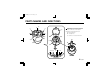
L53D4/US GB 1998, 3, 10 PARTS NAMES AND FUNCTIONS 3 4 1 1 2 7 2 5 9 A Manual pan, tilt and rotation The angle of the lens can be adjusted manually in ranges indicated below.
L53D4/US GB 1998, 3, 10 PARTS NAMES AND FUNCTIONS 1 Camera unit fixing screws (4) These screws are used to attach the camera unit to the base. Tighten the four screws evenly when attaching the camera unit. 2 Screw openings for base installation These openings are to attach the base to the ceiling or a wall using the four supplied tapping screws. 3 CAMERA (VIDEO) OUT terminal screw Video signal output terminal.
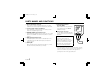
L53D4/US GB 1998, 3, 10 PARTS NAMES AND FUNCTIONS 8 Secondary lens cover 9 Lens F Focus ring To set the focus, loosen the focus ring knob, then turn the ring towards ∞ (infinity) or N (near) as necessary. When the focus is set as desired, tighten the focus ring knob. G Zoom ring To adjust the viewing range (zoom), loosen the zoom ring knob, then turn the ring towards T (the range will be smaller and the subject larger) or W (the range will be wider and the subject smaller) as necessary.
L53D4/US GB 1998, 3, 10 PREPARATIONS AND CONNECTIONS Concerning the coaxial cable To connect the camera to peripheral devices, use a coaxial cable with BNC plug. • Cable type RG-6U (5C-2V), 500 m maximum. • Cable type RG-11U (7C-2V), 600 m maximum. If the type of peripheral devices connected, the type of cable used and/or the cable length are not as specified, the image and synchronization signals may not be transmitted correctly. CAUTION: Use CCTV/Video grade coaxial cable.
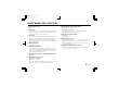
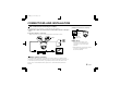
L53D4/US GB 1998, 3, 10 CONNECTIONS AND INSTALLATION Basic connections for monitoring or recording The peripheral devices (VCR, monitor, etc.) and cables are sold separately. 1 Make the video signal connection between the camera and the monitor or time lapse VCR. 2 Plug the AC adaptor to a wall outlet. Adjust the picture on the monitor using the Brightness and Contrast controls. (Example of connection to a monitor) VIDEO IN : VIDEO IN Fig. 1 : VIDEO OUT NOTE: (Fig.
L53D4/US GB 1998, 3, 10 CONNECTIONS AND INSTALLATION Coaxial cable connection 1 2 Cut and prepare the extremity of the coaxial cable (sold separately), as illustrated. Attach the coaxial cable to the base.
CONNECTIONS AND INSTALLATION 2 Install the camera unit onto the base. Connect the video signal cable plug (B) and the power supply cable plug (C) from the base to their respective connectors on the camera unit. Then install the camera unit onto the base. 3 Securely tighten the four camera unit fixing screws (D) evenly. 1 2 Loosen the four camera unit fixing screws (A) evenly. 3 Remove the camera unit.
L53D4/US GB 1998, 3, 10 SETTINGS AND ADJUSTMENTS The digital process may disturb the image for about 5 seconds after the camera is turned on. Factory settings The camera is shipped from the factory with the following settings. These settings should give adequate results under normal conditions. If the settings need to be modified, please consult the reseller or installer. A: Color adjustment (B: blue gain, R: red gain) volume controls . . . About the center B: WB (white balance) switch . . . . . . . . . .
L53D4/US GB 1998, 3, 10 SETTINGS AND ADJUSTMENTS ☞ In this case, the backlight compensation default setting may not give good results. To obtain a better image, set the BLC switch to 1 (ON), then turn the LEVEL volume control to the right until the desired correction level is obtained. LEVEL Manual white balance adjustment To set the colors, first set the WB switch to M, then adjust as desired, using the (B and R) color adjustment volume controls.
L53D4/US GB 1998, 3, 10 SETTINGS AND ADJUSTMENTS Line phase adjustment When using a camera switcher to connect two cameras or more to one monitor, there may be a vertical roll of the images when switched, if the phases differ. In such a case, adjust as described below. 1 2 Set the SYC switch, on the connected cameras, to 1. Using the camera switcher, switch the display on the monitor from camera 1 to camera 2. Adjust the L-PHASE volume control on camera 2 until the vertical roll of the image stops.
L53D4/US GB 1998, 3, 10 SETTINGS AND ADJUSTMENTS Zoom and focus adjustments After the camera has been installed, the zoom and focus must be adjusted while viewing on a monitor the transmitted image. 1 Remove the lens cover, then press on both sides of the secondary lens cover to remove it. 2 Loosen the zoom ring knob, then turn the ring towards T or W as necessary. • T (zoom in) side The range will be smaller and the subject larger.
L53D4/US GB 1998, 3, 10 TROUBLESHOOTING Before taking the camera for repairs, please check below to make sure that the camera is used correctly. If it still does not perform correctly, please consult your dealer or a Sanyo Authorized Service Center.
L53D4/US GB 1998, 3, 10 SPECIFICATIONS TV system Based on the NTSC color system Scanning system 525 TV lines, 60 field/sec., 2:1 interlace Image device Interline transfer method, 1/3 inch solid state CCD Lens F2.0 ∼ 2.7, f=2.6 ∼ 5.
L53D4/US GB 1998, 3, 10 SPECIFICATION DIMENSIONS 112mm 83.5mm 11mm φ 110mm 66 .7 m m φ φ 83.5mm 6- 4.