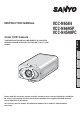
INSTRUCTION MANUAL VCC-N6584 VCC-N6695P VCC-N4598PC Ё᭛ㅔԧ Deutsch Español Français THIS INSTALLATION SHOULD BE MADE BY A QUALIFIED SERVICE PERSON AND SHOULD CONFORM TO ALL LOCAL CODES. English Color CCD Camera Please read this instruction manual carefully in order to ensure correct installation. In addition, be sure to read carefully the electronic manual contained in the supplied CD-ROM to ensure correct operation of the camera. This manual covers 3 models.
Contents Information to User ......................................................................................................2 Preparations ................................................................................................................4 Parts Names and Functions ........................................................................................5 Viewing Live Images on a Monitor (Basic Connections) .............................................6 Camera Settings ....................
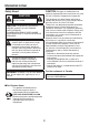
Information to User Safety Guard CAUTION: Changes or modifications not expressly approved by the manufacturer may void the user’s authority to operate this equipment. CAUTION RISK OF ELECTRIC SHOCK DO NOT OPEN This equipment has been tested and found to comply with the limits for a Class B digital device, pursuant to Part 15 of the FCC Rules. These limits are designed to provide reasonable protection against harmful interference in a residential installation.
Information To User For EU Users Please note: Your SANYO product is designed and manufactured with high quality materials and components which can be recycled and reused. This symbol means that electrical and electronic equipment, at their end-of-life, should be disposed of separately from your household waste. Please dispose of this equipment at your local community waste collection/recycling centre. In the European Union there are separate collection systems for used electrical and electronic products.
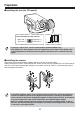
Preparations ■ Installing the lens (for CS mount) Lens terminals for auto iris lens Brake coil (+) Brake coil (–) Drive coil (–) Drive coil (+) 5 mm/0.2 in. or less • If using a C mount lens, install a commercially-available adapter ring. • The shape of the lens plug may not mach depending on the type of lens being used. If the shape does not match, contact the place of purchase or an authorized service agent.
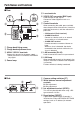
Parts Names and Functions ■ Rear ② ① ⑤ Lens terminals ⑥ VIDEO OUT connector (BNC type) ⑤ Used to output image signals. Connect to video equipment such as a monitor. ④ ⑦ Control terminals ⑥ POWER AC24V -DC12V -- ⑦ LAN ③ GND When connecting the cable, press and hold down the protrusion of the terminal, insert the cable into the terminal, and then release the protrusion.
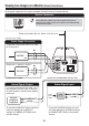
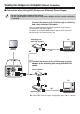
Viewing Live Images on a Monitor (Basic Connections) All the power supplied to the system should be turned off when you connect devices. Monitor Connection Using different cables from those specified here may attenuate the video and/or sync signals and interfere with correct transmission. Thicker than RG-6U (5C-2V): 500 m / 547 yds. max. (Non-PoE power supply) Power Supply Connection To prevent a fire hazard use any UL listed wire rated VW-1.
Camera Settings This camera has been adjusted so that it can be used with a commercially-available DC-type auto iris lens. This may not be suitable for some operating conditions, and so use the switches and controls on the side to make adjustments if necessary. • If correct adjustment cannot be obtained, contact the place of purchase. ❹ ❶ ❸ ❺ ❷ ❹ ❻ The settings for this camera can be changed at the camera and using network operations (some settings may not apply).
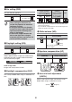
❶ Iris setting (IRIS) Multi-spot metering* Applies backlight compensation to the whole image (MULTI). This sets the lens aperture. Automatic iris (AI) Electronic iris (EI) High Normal Center-zone metering Applies backlight compensation to the center of the image (CENT). OFF (For indoor use) • When setting the electronic iris, * If the background for the objects is extremely dark, set to center-zone metering.
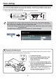
Viewing Live Images on a Computer (Network Connection) ■ Connection when Using PoE (Power over Ethernet) Power Supply • Do not use the power supply of the camera. • Do not supply power to the PoE hub or PoE power adapter until the camera installation is finished. Connect the camera to the LAN through a switching hub using shielded LAN cables. You may extend the transmission distance by using multiple switching hubs with PoE support.
■ Connection when Not Using PoE (Power over Ethernet) Power Supply Internet connection (P11) PC Router or ADSL modem LAN cable (straight type) 11 11 Direct connection Monitor PC LAN cable (crossover type) POWER ALARM OUT VIDEO OUT ALARM IN AC24V -DC12V -LAN GND COM LINK CLASS 2 WIRING LAN connection Power Supply (AC24V/DC12V) LAN cable (straight type) PC 11 Switching hub 11 ✱1: LAN cable: CAT5 or higher, straight type, 100 m / 109 yds max.
Viewing Live Images on a Computer (Network Connection) ■ About the “ Internet connection” Port forwarding settings will need to be carried out for the image port (HTTP/UDP) of the broadband router. x Port 1: JPEG/H.264 HTTP Port number: Initial value 80 (TCP) IP address: Initial value 192.168.0.2 Port number: Initial value 80 (TCP) • Set to match the LAN To LAN port To WAN port Router x Port 2: H.264 UDP Unicast Port number: Initial value 3939 (UDP) IP address: Initial value 192.168.0.
Network Settings 1 Network Settings Set the TCP/IP settings in accordance with the operating system of the computer being used. ☞ The screens below explain the procedure when using Windows Vista. If using Windows XP, click [Start] → [Control Panel] → [Network & Internet Connections], and then click [Network Connections], and then proceed to step 3. 1 Click [Start] → [Control Panel] → [Network and Sharing Center], and then click [Network Connections]. 2 Click [Manage Network Connections].
Network Settings 2 Viewing Camera Images on a Computer 1 2 Start Internet Explorer. 3 In the login screen, enter your username and password, and then click the OK button. 4 Click the desired language button. Enter the camera’s IP address in the address bar, and then press the [Enter] key. (Example of entry) ☞ • Switch to the live image window. (If logging in for the second and subsequent time, the window will switch automatically.) If logging in for the first time, enter the following.
Setting the Camera from the Computer This camera is shipped with the standard setting values and you can start using the camera without performing any settings. If necessary, make appropriate settings or adjustment according to your usage. For details, refer to the electronic manual contained in the supplied CD-ROM. • If you have trouble adjusting the camera, consult your dealer or an Authorized Sanyo Service Center. 1 2 3 Displays the menu setting window (MENU button).
Setting the Camera from the Computer List of menu buttons CAMERA SETTINGS window: This window is used to set the filming settings and operating conditions (such as day/night and motion detection) in accordance with the camera setting environment. NETWORK SETTINGS window: This window is used to set network information (such as IP address and subnet mask).
Using the Supplied CD-ROM ■ Software The following application software is contained in the supplied CD-ROM. You can install and use these applications to use the image data in a wider variety of ways. x VA-SW3050LITE The monitoring software is compatible with cameras manufactured by Sanyo. Live images from multiple cameras can be monitored using a computer (up to a maximum of 128 cameras).
Specifications ■ Camera Television format Color NTSC (VCC-N6584)/PAL (VCC-N6695P) compliant Image sensor 1/3 inch interline transmission-type CCD Effective pixels NTSC: 768(H) × 494(V) PAL: 752(H) × 582(V) Scanning system 2:1 interlaced, NTSC: 525 scanning lines, 60 fields/sec. PAL: 625 scanning lines, 50 fields/sec. Automatic iris control DC type (variable DC level), 4-pin terminal Lens mount CS mount Flange back 12.5 mm ± 0.5 mm/0.5 in. ± 0.02 in.
■ Network Image data compression H.264/JPEG (simultaneous transmission possible) Frame rate H.264 PAL: 25ips (720×576) NTSC: 30ips (720×480) JPEG PAL: 25ips (720×576) NTSC: 30ips (720×480) Resolution H.
License for Software Contained in CD-ROM • Please read carefully the terms and conditions contained in the license agreement that appears on the screen during the software installation process. Provided that you have agreed to all the terms and conditions therein, you may use the software subject to the license agreement. • For information on the other products or services provided by third parties which are introduced in the CD-ROM, please contact each supplier or manufacturer.