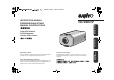
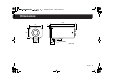
!""#$%&!' )*' +,-.-/0 INSTRUCTION MANUAL BEDIENUNGSANLEITUNG MANUEL D’INSTRUCTIONS Getting Started VCC-WD8575P About this manual À propos de ce manuel Before installing and using the camera, please read this manual carefully. Be sure to keep it handy for later reference. Avant d’installer et d’utiliser la caméra, veuillez lire ce manuel attentivement. Gardez-le à portée de main pour toute référence ultérieure.
!""#$%&!' )*' +,-.-/0 Contents Precautions . . . . . . . . . . . . . . . . . . . . . . . . . . . . . . . . . . . . . . . . . . . . 3 Dimensions . . . . . . . . . . . . . . . . . . . . . . . . . . . . . . . . . . . . . . . . . . . . 4 Getting Started Connection Examples and Peripheral Devices (Sold separately). . . . . . . . . . . . . . . . . . . . . . . . . . . . . . . . . . . . . . . . 5 Part Names . . . . . . . . . . . . . . . . . . . . . . . . . .
!""#$%&!' )*' +,-.-/0 Contents Specifying Alarm Input. . . . . . . . . . . . . . . . . . . . . . . . . . . . . . . . . . . 38 ALARM IN SETTING . . . . . . . . . . . . . . . . . . . . . . . . . . . . . . . . . . . 38 Using Alarm Input Terminal as DAY/NIGHT Switching . . . . . . . . . 43 Specifying Alarm Output . . . . . . . . . . . . . . . . . . . . . . . . . . . . . . . . . 44 ALARM OUT SETTING (Alarm output) . . . . . . . . . . . . . . . . . . . . .
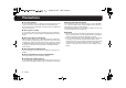
1 !""#$%&!' )*' +,-.-/0 Precautions ■ In case of problem ■ Protect from high temperatures Do not use the unit if smoke or a strange odor comes from the unit, or if it seems not to function correctly. Turn off the power immediately and disconnect the power cord, and then consult your dealer or an Authorized Sanyo Service Center. Do not install close to stoves, or other heat sources, such as spotlights, etc.
2 !""#$%&!' )*' +,-.-/0 Dimensions 136 67 1 127 54 11 28 15.4 24.
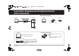
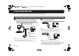
!""#$%&!' )*' +,-.-/0 Connection Examples and Peripheral Devices (Sold separately) ■ For Camera Setup Only Monitor Digital Video Recorder Records Images Camera Monitor Camera Camera Control Unit Monitor Camera Control Unit (VAC-70) Monitors images from the camera. Also available as settings screen. Digital Video Recorder Records images on a hard disk.
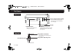
3 !""#$%&!' )*' +,-.-/0 Part Names Getting Started Rear Panel Video Output Terminal (VIDEO OUT) Power Indicator (POWER) Illuminates red when power is supplied. Connects to the Video Input Terminal (VIDEO IN) of the monitor or the recorder. See page 9. VIDEO OUT ALARM Alarm I/O Terminal (ALARM IN, OUT, COM) POWER COM COM OUT IN GND DC12V AC24V Connects with an external alarm device. (Push Lock) • See page 10 for connection.
!""#$%&!' )*' +,-.-/0 Part Names Side Panel CURSOR Lens Iris Output Terminal (LENS) SET Connects with the lens plug of the auto iris type lens (sold separately). (See next page) Bracket CURSOR Button Moves the cursor during each setting. (See page 13) SET Button Used for viewing, switching over and determining screen for each setting. (See page 13) Top Panel Flange Back Lock Screw Locks the flange back adjusting lever.
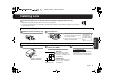
!""#$%&!' )*' +,-.-/0 Installing Lens You are recommended to use any DC type and CS mounting lens equipped with an auto iris. Note: • Apply adapter ring (sold separately) when you use any C mounting lens. • Use any lens of which length (L: see the figure to the right) of the mounting screw is within 5 mm; otherwise you may fail to install or damage the lens. L Steps for Installing Lens Install the lens.
4 !""#$%&!' )*' +,-.-/0 Connecting Devices Note: • All the power supplied to the system should be turned off when you connect devices. • Incorrect connections may cause failure and/or smoking; carefully read this and other instruction manuals for each device for proper connections.
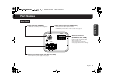
5 !""#$%&!' )*' +,-.-/0 Connecting Devices Connecting Alarm Devices Connect the unit with External Alarm or Beeper. External Beeper or Indicator External Alarm Switch or IR Sensor ALARM Connection COM COM IN OUT Note: For alarm device connection, configure an alarm setting for this unit. See pages 38 and 44.
!""#$%&!' )*' +,-.-/0 Connecting Devices Installing Camera Install the camera in a correct location so that the intended object can be monitored properly. You should also adjust on the monitor side. • You can change the bracket topside down, depending on the installation spot for the camera (see below).
!""#$%&!' )*' +,-.-/0 Connecting Devices Adjusting Flange Back Flange back adjustment may be required to correct a focal distance error generated due to attachment thickness of the installed lens. Normally you do not have to make any adjustment, however, you can adjust focus of the installed lens with auto iris, when it provides images out of focus at the maximum telephoto position. To adjust the flange back, follow the steps below.
1 !""#$%&!' )*' +,-.-/0 Overview of Settings and Adjustments You can configure various adjustments and preference settings on the monitor screen. CURSOR Button Buttons used for settings Press the button up and down or side to side to select an item or set up. • Press and hold the button to continually change the items that appear.
2 !""#$%&!' )*' +,-.-/0 Basic Operation for Settings and Adjustments An Example for Basic Operation for Settings and Adjustments Indicates to press the CURSOR button up and down to select an item. Indicates to press the CURSOR button side to side to switch over to other values.
!""#$%&!' )*' +,-.-/0 Selecting Display Language For accessing the MAIN MENU, see page 13 – 14. You can change the language displayed on the settings and adjusting screens.
3 !""#$%&!' )*' +,-.-/0 Naming Cameras For accessing the MAIN MENU, see page 13 – 14. You can give a name (title) to each camera. The specified names are displayed on the monitor so that you can easily distinguish the monitoring images when you use multiple cameras.
!""#$%&!' )*' +,-.-/0 Naming Cameras 3 Select “POSITION” – “SET” and press the SET button. TITLE SETTING 4 On the monitor screen, determine the location where the name should be displayed by pressing the button up-down or side to side; and then press the SET button. ABCDEFGHIJKLM NOPQRSTUVWXYZ 0123456789 :ID CAM1 CAM1???????????? POSITION SET PRESET MENU OFF BACK SET SET RReturns to the settings screen.
!""#$%&!' )*' +,-.-/0 Adjusting Synchronization Error For accessing the MAIN MENU, see page 13 – 14. By default, the synchronization adjustment for the camera is performed internally (INT). However, you must make adjustments in the Line Lock (L-L) Setting screen, if the monitor screen seems out of sync after switching over among multiple cameras using AC 24 V. • If using this camera as the second or subsequent camera, adjust the roll using this setting.
4 !""#$%&!' )*' +,-.-/0 Adjusting Auto Iris For accessing the MAIN MENU, see page 13 – 14. This unit is designed to accept the DC type auto iris lens (sold separately) and is factory-configured to be ready-for-use with the optional lens. However, you can configure and/or make adjustments for preferred brightness depending on the environment, condition or other optional lens you use.
5 !""#$%&!' )*' +,-.-/0 Adjusting Auto Iris IRIS SETTING (AI: Auto Iris) (continued) 3 Select “IRIS STOP” and specify an iris value (0 – 17). RFinishes the settings screen and returns to the normal monitoring screen. • If you want to return to the previous screen, select “BACK” and press the SET button. IRIS SETTING DC DRIVE 4 Set “MENU” to “END” and press the SET button.
!""#$%&!' )*' +,-.-/0 Adjusting Electronic Iris (For Manual or Fixed Iris Lens) For accessing the MAIN MENU, see page 13 – 14. If you need to adjust the brightness for using manual iris lens or fixed iris lens, follow the steps below. • Adjust the iris manually.
!""#$%&!' )*' +,-.-/0 Correcting Backlight For accessing the MAIN MENU, see page 13 – 14. If the images of subjects are not clear because of backlight, correct it by adjusting conditions or changing correction method.
1 !""#$%&!' )*' +,-.-/0 Correcting Backlight CENT (BLC SETTING) (Center-weighted Metering) 1 Locate the upper left corner of an area for which you want to correct backlight, and then press the SET button. 2 Specify the correction area size, and press the SET button. BLC SETTING BLC SETTING [SIZE] [POSITION] SET SET RThe “SIZE” screen appears. MEMO: Here, determine the upper left position of the correction area.
2 !""#$%&!' )*' +,-.-/0 Correcting Backlight CENT (BLC SETTING) (Center-weighted Metering) (continued) 3 To correct areas other than center, select from the options. 4 Specify a metering level (0 – 15). BLC WINDOW WEIGHTING BLC WINDOW WEIGHTING 0 0 0 0 15 PRESET MENU OFF BACK (When TOP is selected) TOP BOTTOM LEFT RIGHT CENTER : Upper : Lower : Left : Right : Area set in step 2.
!""#$%&!' )*' +,-.-/0 Correcting Backlight MULT (BLC SETTING) (Multi-spot Metering) 1 Select an item and specify each level (0 – 15). BLC SETTING [BLC WEIGHT] 7 [BRIGHT] 7 PRESET MENU OFF BACK BLC WEIGHT : Effectiveness of backlight correction BRIGHT : Brightness of the portion to which backlight correction is applied • The greater the number, the greater the effect becomes. 25 English 2 Set “MENU” to “END” and press the SET button.
3 !""#$%&!' )*' +,-.-/0 Setting Wide Dynamic Range For accessing the MAIN MENU, see page 13 – 14. Correction is made for simultaneous monitoring of subjects which are different in brightness, one in a dark room and another in bright outdoor environment, for example.
!""#$%&!' )*' +,-.-/0 Setting Wide Dynamic Range 2 Set “MENU” to “END” and press the SET button. RFinishes the settings screen and returns to the normal monitoring screen. • If you want to return to the previous screen, select “BACK” and press the SET button. Note: • Setting “WIDE-D” to “ON” will switch “BLC” to “OFF”. (See page 22) • Afterimages may occur around contours of a moving object.
!""#$%&!' )*' +,-.-/0 Increasing Electronic Sensitivity For accessing the MAIN MENU, see page 13 – 14. If subject images are not very clear due to ambient darkness, you can increase the camera sensitivity by specifying the “SENSE UP” (increasing electronic sensitivity) option. Note: If you specify this option, the exposure time of CCD will be extended as it grows dark.
4 !""#$%&!' )*' +,-.-/0 Specifying Shutter Speed For accessing the MAIN MENU, see page 13 – 14. You can specify the electronic shutter speed to capture fast-moving subjects. Note: With the increase in shutter speed number, faster movement can be captured, though the image becomes darker.
15 !""#$%&!' )*' +,-.-/0 Adjusting DAY/NIGHT Function For accessing the MAIN MENU, see page 13 – 14. The DAY/NIGHT function automatically switches over between COLOR and B/W mode depending on the ambient brightness; for example, choosing COLOR mode during daytime, and B/W mode for nighttime monitoring with its increased sensitivity in a darker environment.
1 !""#$%&!' )*' +,-.-/0 Adjusting DAY/NIGHT Function D/N SETTING-AUTO 1 Select “AGC MAX GAIN” and specify the maximum value of gain for AGC*1. D/N SETTING - AUTO AGC MAX GAIN BURST LEVEL NORM OFF MID NORM : Normal setting MID : Setting with which a bright image is obtained in a lower illuminance than the NORM setting. HIGH : Setting with which a bright image is obtained in a lower illuminance than the MID setting.
1 !""#$%&!' )*' +,-.-/0 Adjusting DAY/NIGHT Function D/N SETTING-COLOR 1 Select “AGC MAX GAIN” and specify the maximum value of gain for AGC*. D/N SETTING - COLOR AGC MAX GAIN ■ GAIN SETTING Select “OFF” and press the SET button, and you can specify a value for the fixed gain.
11 !""#$%&!' )*' +,-.-/0 Adjusting DAY/NIGHT Function D/N SETTING-B/W (Black and white) 1 Select “AGC MAX GAIN” and specify the maximum value of gain for AGC*1. ■ GAIN SETTING Select “OFF” and press the SET button, and you can specify a value for the fixed gain. (0 – 7) D/N SETTING - B/W AGC MAX GAIN BURST GAIN SETTING NORM OFF 7 • The greater the number, the higher the sensitivity becomes in dark places.
12 !""#$%&!' Adjusting White Balance WHITE BALANCE +,-.-/0 For accessing the MAIN MENU, see page 13 – 14. With its default Auto-tracing White Balance (ATW) setting, this unit is able to obtain natural colors even when the light source is changed. However, you may manually change the white balance settings or its mode to obtain better tone, especially when the screen color does not match actual objects.
1 !""#$%&!' )*' +,-.-/0 Adjusting White Balance ATW MASKING (Masking for ATW) 1 Select an area to be masked and specify “ON”. ATW MASKING TOP BOTTOM LEFT RIGHT CENTER OFF OFF OFF OFF OFF PRESET MENU OFF BACK CENTER RFinishes the settings screen and returns to the normal monitoring screen. • If you want to return to the previous screen, select “BACK” and press the SET button.
13 !""#$%&!' )*' +,-.-/0 Adjusting White Balance AWC SETTING (One-Push Adjustment) 1 Select “AWC LOCK” – “SET”. ■ To perform fine adjustment of color In the “AWC SETTING” screen, select “GO TO MWB” – “SET”, and press the SET button. R The “MWB SETTING” screen appears. Specify values manually.
1 !""#$%&!' )*' +,-.-/0 Adjusting White Balance MWB SETTING (Manual White Balance) 1 Select “R” or “B” to adjust tint (0 – 255). MWB SETTING [OFFSET] R ú 70 B ú 70 PRESET MENU OFF BACK R : Adjusting Red B : Adjusting Blue • The greater the number, the deeper the tint becomes. 37 English 2 Set “MENU” to “END” and press the SET button. RFinishes the settings screen and returns to the normal monitoring screen.
1 !""#$%&!' )*' +,-.-/0 Specifying Alarm Input For accessing the MAIN MENU, see page 13 – 14. If you have connected an external door switch or an infrared sensor to the alarm input terminal (ALARM IN) on the rear panel, specify the following settings. (For connecting alarm devices, see page 10; for the “Alarm Output” settings, see page 44).
14 !""#$%&!' )*' +,-.-/0 Specifying Alarm Input 3 Select “MASKING” and specify “ON” and press the SET button. 4 Select a masking area and specify “ON”. MOTION MASKING MOTION SETTING MASKING SENSITIVITY DURATION ON SET 5S TOP BOTTOM LEFT RIGHT CENTER ON OFF OFF OFF OFF PRESET MENU OFF BACK SET SET PRESET MENU OFF BACK RThe “MOTION MASKING” screen appears. MEMO: Apply masking to what should not be motion-detected; e.g.
25 !""#$%&!' )*' +,-.-/0 Specifying Alarm Input 6 Select “SENSITIVITY” – “SET” and press the SET button. OFF SET 5S 9 Select “Y-LEVEL” and specify a luminance level (1 – 10). SET PRESET MENU difference level (1 – 10). • The greater the number, the lower the responsiveness to the brightness variation, such as lighting on or off conditions.
2 !""#$%&!' )*' +,-.-/0 Specifying Alarm Input I Select “DURATION” and specify a time until the next alarm input becomes enabled. MOTION SETTING MASKING SENSITIVITY DURATION OFF SET 5S PRESET MENU OFF BACK • Select from: 5S, 10S, 15S, 20S, 30S, 1M, 2M, 3M, 4M or 5M (S = second, M = minute) Note: A new detection or an alarm output cannot be performed until the specified time of duration elapses. J Set “MENU” to “BACK” and press the SET button.
2 !""#$%&!' )*' +,-.-/0 Specifying Alarm Input alarm detection. ALARM IN SETTING MODE POLARITY MOTION MOTION SET ZOOM ZOOM TIME DURATION ALM NO OFF SET OFF 5S 5S PRESET MENU OFF BACK • Select from: OFF (no zoom), x 1.4, x 2.0, x 2.5. Note: • If you specify the “ZOOM” function, the center of the screen will be electronically zoomed in automatically when an alarm signal is supplied from external devices such as door switch or infrared sensor, etc.
21 !""#$%&!' )*' +,-.-/0 Specifying Alarm Input Using Alarm Input Terminal as DAY/NIGHT Switching 1 Set “MODE” to “COLOR”. 2 Select “POLARITY” and specify a polarity for the signal.
22 !""#$%&!' )*' +,-.-/0 Specifying Alarm Output For accessing the MAIN MENU, see page 13 – 14. If you have connected an external beeper or indicator to the alarm output terminal (ALARM OUT) on the rear panel, specify the following settings. You can also obtain a notification on the screen while an alarm occurs. (For connecting alarm devices, see page 10.
2 !""#$%&!' )*' +,-.-/0 Specifying Alarm Output ALARM SIGN (Alarm display) 1 Select “ALARM SIGN” on the “ALARM SETTING” screen and specify a displaying time.
23 !""#$%&!' )*' +,-.-/0 Correcting Gamma Characteristic For accessing the MAIN MENU, see page 13 – 14. If the contrast or brightness of the monitor screen does not seem appropriate, change the mode for Gamma correction*. OPTION MAIN MENU OPTION (SET) LANGUAGE TITLE SYNC EXPOSURE DAY/NIGHT WHITE BALANCE ALARM OPTION PRESET MENU SET OFF INT SET AUTO ATW SET SET OFF END SET GAMMA GAMMA APERTURE MIRROR NEGA/POSI PRIVACY MASK EL ZOOM 0.
2 !""#$%&!' )*' +,-.-/0 Accentuating Subject Outline For accessing the MAIN MENU, see page 13 – 14. By specifying the APERTURE* setting, you can accentuate the outline of the subject when its image is blurred and unidentifiable. MAIN MENU OPTION (SET) LANGUAGE TITLE SYNC EXPOSURE DAY/NIGHT WHITE BALANCE ALARM OPTION PRESET MENU OPTION SET OFF INT SET AUTO ATW SET SET OFF END SET APERTURE ON GAMMA APERTURE MIRROR NEGA/POSI PRIVACY MASK EL ZOOM 0.
2 !""#$%&!' )*' +,-.-/0 Inverting Images (horizontal/vertical) For accessing the MAIN MENU, see page 13 – 14. If a camera is installed upside down, or monitoring subjects in a mirror or viewing backward from vehicle, you can invert the images vertically and/or horizontally.
24 !""#$%&!' )*' +,-.-/0 Inverting Images (Brightness/Hue) For accessing the MAIN MENU, see page 13 – 14. You can record negative images of color film as positive images by reflecting the brightness and hue of the video signal. OPTION MAIN MENU OPTION (SET) LANGUAGE TITLE SYNC EXPOSURE DAY/NIGHT WHITE BALANCE ALARM OPTION PRESET MENU SET OFF INT SET AUTO ATW SET SET OFF END SET NEGA/POSI GAMMA APERTURE MIRROR NEGA/POSI PRIVACY MASK EL ZOOM 0.
5 !""#$%&!' )*' +,-.-/0 Hiding Partial Image (Privacy Protection) For accessing the MAIN MENU, see page 13 – 14. If privacy protection is required for any shot, apply the masking feature for any position to be prevented from being presented. You can also lock the setting and its cancellation by specifying a password.
!""#$%&!' )*' +,-.-/0 Hiding Partial Image (Privacy Protection) PRIVACY MASK SETTING (continued) 3 Locate the upper left corner of an area for which you want to mask, and then press the SET button. MASK 1 SET [POSITION] SET SET RThe “SIZE” screen appears. • From the datum point at the upper left corner of the area, the size can be scaled up or down, as well as side to side. RThe “PRESET” and “MENU” appear on the screen.
!""#$%&!' )*' +,-.-/0 Hiding Partial Image (Privacy Protection) ■ To lock (protect) the settings: 1 Select “PASSWORD LOCK” – “OFF” and press 2 Enter the password (4 numerical values) and press the SET button. the SET button. PASSWORD PRIVACY MASK SETTING PASSWORD LOCK OFF PASSWORD CHANGE SET MASK SET SET 1234 SET SET SET Move cursor. MENU BACK BACK RThe “PASSWORD” screen appears.
1 !""#$%&!' )*' +,-.-/0 Hiding Partial Image (Privacy Protection) ■ To change password: 1 Select “PASSWORD CHANGE” – “SET” and 2 Enter the current password and press the SET button. press the SET button. PASSWORD PRIVACY MASK SETTING [NOW PASSWORD] PASSWORD LOCK ON PASSWORD CHANGE SET MASK SET SET 1234 SET SET SET MENU MENU BACK BACK RThe “NEW PASSWORD” screen appears. RThe “NOW PASSWORD” screen appears.
2 !""#$%&!' )*' +,-.-/0 Multiplying Magnitude of Electronic Zoom For accessing the MAIN MENU, see page 13 – 14. In addition to zooming on the lens side, you can obtain further zooming by magnifying an electronic zoom factor. MAIN MENU OPTION (SET) LANGUAGE TITLE SYNC EXPOSURE DAY/NIGHT WHITE BALANCE ALARM OPTION PRESET MENU OPTION SET OFF INT SET AUTO ATW SET SET OFF END SET EL ZOOM GAMMA APERTURE MIRROR NEGA/POSI PRIVACY MASK EL ZOOM 0.
!""#$%&!' Settings Screens List [LANGUAGE] LANGUAGE : Switches display language among English, German and French. (See page 15) [TITLE] TITLE SETTING : Names camera. (See page 16) [SYNC] (INT/L-L) L-L SETTING (L-L) : Adjusts line lock phase. (See page 18) [EXPOSURE] EXPOSURE SETTING IRIS (AI/EI) IRIS SETTING (AI) : Adjusts for auto iris lens. (See page 19) IRIS SETTING (EI) : Adjusts for manual iris lens.
3 !""#$%&!' )*' +,-.-/0 Settings Screens List MASK SET : Specifies masking on the screen for privacy protection. (See page 50) EL ZOOM (OFF/x1.4/x2.0/x2.5/MANU) : Specifies electronic zoom factor. (See page 54) ■ Useful Operations • Putting titles to camera images: → TITLE SETTING (See page 16). • Capturing clear image of fast-moving subject by increasing shutter speed: → SHUTTER (See page 29).
!""#$%&!' )*' +,-.-/0 Troubleshooting Before seeking repair service, please review the following points first. If the trouble persists, contact your local sales agent or installer.
!""#$%&!' )*' +,-.-/0 Specifications Pickup device 1/3” CCD Effective pixels 752 (H) x 582 (V), PAL Privacy masking OFF/ON, Up to 8 spots, Lockable with password Horizontal resolution More than 480 TV lines DAY/NIGHT AUTO / COLOR / B/W, specifiable COLOR / B/W switching sensitivity for AUTO mode, switchable COLOR / B/W mode working with external terminal (during COLOR mode), switchable ON/OFF for color burst for B/W mode. Electronic zoom x2.
Printed on recycled paper Gedruckt auf recyceltem Papier PapierImprimé sur du papier recyclé SANYO Electric Co., Ltd.