VDC-HD3300/HD300P VDC-HD3100/HD3100P Features of This Camera Specifications Name and Function of Each Component Connections Lens Installation Lens Adjustment Viewing Firmware Version Introduction1/15
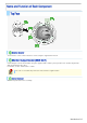
The camera supports network operation. By simply connecting a LAN cable to it, you can construct the most advanced network monitoring system. From the Web browser (Internet Explorer) installed on your PC, you can operate the camera via the network in an easy-to-use manner. In addition, it is a PoE product that can be powered through a LAN cable, so you can install it in locations where there is no power outlet nearby.
Image pickup device 1/3" CMOS sensor Effective pixels 16:9 1920 (H) × 1080 (V), 4:3 2288 (H) × 1712 (V) Lowest image illumination 50IRE: 1.0 lx (at F1.2, color mode, high gain) 50IRE: 0.06 lx (at F1.2, black-and-white mode, high gain) Video S/N ratio 50dB (when AGC is “OFF”) Lens Built-in varifocal lens f=3 to 9mm, F1.2 to 2.
Image/video compression H.264/JPEG Video size (H.
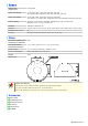
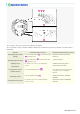
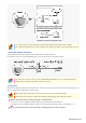
To remove the cover, remove the three screws using the supplied hex wrench. Connecting the camera and monitor using the supplied cable enables you to perform focus and iris adjustments while monitoring the live video. For details, see the “Connections” section. You can use crocodile clip connectors instead of the supplied cable. This cover protects the lens assembly.
These buttons allow you to perform the following operations. These operations may be performed with the Web browser installed on your PC. For details, refer to the linked information.
For the detailed procedures for connecting terminals and cables, refer to the “Connections” section. Use these coupling holes to mount the camera to the separately-sold base bracket. Use this socket to connect the camera to your PC to enable network operation. Use this cable to connect a 24 VAC or 12 VDC power supply. There is no power indicator on the camera. Alarm input cable: Connect an external switch, infrared sensor, or other device to detect alarm conditions such as the entry of an intruder.
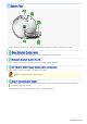
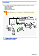
Perform the following connections according to the installation environment and application of your camera. A Alarm Cable Connection B Power Connection C Network Connection D Camera Monitor Connection Before attempting the following connections, be sure to turn off all components of your system. Improper connection may cause smoke or failures.
After connecting an alarm device, configure the input conditions for the corresponding alarm input cable via network operation on the ALARM SETTINGS screen. To use the alarm input cable as Day/Night switching signal path, follow the steps below. ( (This function is supported only by VDC-HD3300P/VDC-HD3300.)) Under [DAY/NIGHT], set [DAY/NIGHT] to “COLOR” and select the cable you want to use in [EXT ALARM]. On the ALARM SETTINGS screen, in [POLARITY], select the signal polarity of the alarm input terminal.
Use a LAN cable no longer than 100 m (109.4 yards) with the shield type CAT5 or higher. The supported Web browser is Internet Explorer Ver.6.0 SP2 or higher, or Internet Explorer Ver.7.0. About the internet connection Port forwarding for the video port must be enabled on the broadband router. For details on how to set port forwarding, please refer to your router's Instruction manual.
To perform focus adjustment with the camera, remove the dome cover, connect the supplied cable to the MON OUT socket of the camera, and connect a monitor to the camera using a video cable. ( A ) After adjustment, be sure to remove the monitor cable. You can use crocodile clip connectors instead of the supplied cable.
After installing the lens to the camera, you need to perform the following adjustments for the lens. A Angle of View/Focus Adjustment (FOCUS ASSIST) B Iris Adjustment (IRIS) Using network operation, you can use the focus assist function to adjust the focus. Use the focus assist function to accurately focus on subject in high-resolution megapixel image because otherwise doing so would be extremely difficult.
3 Adjust the lens orientation. Then adjust angle of view using the zoom ring, and the focus using the buttons. PEAK HOLD: Shows the value of the maximum focus level. INDICATOR: Shows the value of the current focus level. Adjusting focus 1 Use the NEAR/FAR button to roughly focus on the subject. Adjust by monitoring the video image on the monitor. 2 Press the SET button. The camera automatically focuses on the subject.
If the camera produces too dark, too bright, or other incorrect video images, adjust the lens iris. 1 Press the SET button for 2 seconds or more. The monitor now shows the SELECT MENU screen. On the SELECT MENU screen, all information is displayed in English. 2 Select [IRIS] using the NEAR/FAR button and press the SET button. The monitor now shows the iris adjustment screen. 3 Press the NEAR/FAR button to adjust the iris level.
On the FIRMWARE VERSION screen, you can check the firmware version, IP address, and other information on the camera. The firmware version can also be checked via network operation on the OPTION SETTINGS screen. 1 Press the SET button for 2 seconds or more. The monitor now shows the SELECT MENU screen. On the SELECT MENU screen, all information is displayed in English. 2 Select [FIRMWARE VERSION] using the NEAR/FAR button and press the SET button. The monitor now shows the FIRMWARE VERSION screen.
VDC-HD3300/HD300P VDC-HD3100/HD3100P From Connection to Network Operation Live Video Monitoring Alarm Detection and Output Software Information Configuration menu quick reference tables Quick Operation Guide1/10
Follow the steps below to set up and connect the camera to your PC. You can use alarm video recording, bidirectional audio communications, and other standard features of the camera, in addition to normal live video monitoring. 1 Connect the power cable to the power terminals. Use a 24-VAC or 12-VDC power supply. Do not turn on the camera until you complete all connections. 2 Connect the network (LAN) socket to your PC using a LAN cable.
To enable surveillance with clear video images, adjust the lens focus while viewing the subject on the FOCUS ASSIST screen displayed on the monitor. After adjustment, be sure to remove the monitor cable. 6 Access the camera from your PC's Web browser. Live video appears on the live screen. Now, you can perform all network operations from your PC.
If you are operating the camera for the first time, check the factory default video/image conditions on the CODEC/STREAMING SETTINGS screen. Change the default settings as necessary. For details, refer to the “CODEC/STREAMING SETTINGS” section. 16:9 (Default) → 4:3 You can switch between JPEG image and H.264 video using the buttons on the live screen control panel. The screenshot above shows the factory default settings for each video/image condition.
If you are operating the camera for the first time, check the factory default alarm detection conditions on the ALARM SETTINGS screen. Change the default settings as desired. For details, refer to the “ALARM SETTINGS” section. You can configure the camera to detect alarm conditions via the “alarm input terminals” or “built-in motion sensor”. For how to configure the camera to detect alarm conditions via the alarm input terminals, refer to the “Alarm Input/Output Terminal Connections” section.
B Detecting motion in specific areas In [MOTION], after selecting a motion sensor type, click detailed configuration screen. DETAIL to configure the detection conditions on the You can configure the camera to “automatically output alarm signals” or “remotely (manually) output alarm signals”. You can configure the camera to automatically output an alarm signal when either of its alarm input terminals receives an alarm signal.
Setting Item ALARM OUT1/ 2 (Alarm output terminal number) POLARITY (Signal polarity) ALARM OUT TIME (Alarm output time) Default Setting OFF (Disables alarm Optional Setting REMOTE (Enables remote alarm output.) output.) NO NC 5SEC (Ex.: Beeps a warning 10SEC to 5MIN, CC (Stops alarm output when for 5 sec.) Remote Alarm button is clicked.
You can install the following software on your PC to extend the capabilities of your surveillance system. The CD-ROM that comes with the camera includes all the supplied software. A H.264 Plug-in (Plug-in for monitoring live video as high-quality moving images) This plug-in software is required to display H.264 video on the live screen. Be sure to install it on each computer from which you access the camera via network operation.
Click MENU on the control panel to display the administrator configuration menu that includes a series of menu selection buttons. If you are a surveillance system administrator, use these buttons to configure necessary settings according to the installation environment and application of your camera. Configuration Related to Network Connection Operation Changing the camera's IP address. Configuration Screen (Menu) NETWORK SETTINGS Using SANYO's DDNS service. Using SSL communication. Streaming H.
Optional Configuration Operation Configuration Screen (Menu) Updating the camera's firmware to the latest version.
VDC-HD3300/HD300P VDC-HD3100/HD3100P Preparing Your Computer for Network Operation Setting Up IP Addresses Automatically (Auto IP Setup) Checking the operating environment Configue the network information on your PC Operation Privileges and Login Users Before You Begin Network Operation1/13
Follow the steps below to prepare your computer for network operation. For detailed procedure, refer to the linked information. 1 Assign a unique IP address to each camera. If you have newly installed two or more cameras on your network, you can accomplish this by using the supplied “Auto IP Setup” software. 2 Check your operating environment 3 Connect the camera to the network to which your PC is also connected.
If you are installing two or more new cameras on the same local network, you need to change the factory default IP address of each camera to prevent IP address overlap. The supplied “Auto IP Setup” software frees you from this burden by automatically assigning a unique IP address to each camera on your network.
1 Insert the supplied CD-ROM into the CD-ROM drive of your PC. The opening menu appears. 2 Click [Auto IP Setup]. The utility window opens so that you can search cameras. If you encounter a firewall confirmation dialog box, disable the firewall so that your PC can communicate with the camera. 3 Click Search Cameras . The utility searches all cameras on the local network and shows information on each camera one after another.
1 Select the desired camera and click Manual setting . The camera information dialog box opens. 2 Make changes to the camera data and click EXECUTE . This transmits your changes to the camera. You can see the problem of IP address overlap has been resolved in the [Status] row of the list, which has been changed from “CAUTION” to “OK”. You cannot change the model name.
To operate the camera via network operation, you must meet the following operating requirements. IBM PC/AT compatible PC: Operating system: Windows XP Professional/Windows Vista CPU: Core2Duo E6700 2.
1 In [Control Panel], click [Network and Internet Connections]. The [Network and Internet Connections] dialog box opens. 2 Click [Network Connections]. The [Network Connections] dialog box opens. Under [LAN or High-Speed Internet], the icon representing your LAN interface (Ethernet adapter) configuration appears. 3 Right-click on the LAN interface (Ethernet adapter) configuration icon and click [Properties] in the context menu.
4 In the [This connection uses the following items:] list box, select the [Internet Protocol (TCP/IP)] check box. Confirm that the [Internet Protocol (TCP/IP)] check box is selected. If deselected, select the check box. 5 Click [Properties]. The [Internet Protocol (TCP/IP) Properties] dialog box opens, with the [General] tab shown.
6 Select the [Use the following IP address:] radio button and specify the IP address, the subnet mask, and the default gateway. 7 Check the configured settings and click OK . You are now done with the TCP/IP configuration. Close all the dialog boxes that are open. 1 In [Control Panel], click [Network and Sharing Center]. The [Network and Sharing Center] dialog box opens.
2 Click [Manage network connections]. The [Network Connections] dialog box opens. 3 Double-click [Local Area Connection]. The [Local Area Connection Status] dialog box opens. 4 Click [Properties] and, in the confirmation dialog box, click [Continue]. The [Local Area Connection Properties] dialog box opens. 5 Select the [Internet Protocol Version 4 (TCP/IPv4)] check box. Confirm that the [Internet Protocol Version 4 (TCP/IPv4)] check box is selected. If deselected, select the check box.
6 Click [Properties]. The [Internet Protocol Version 4 (TCP/IPv4) Properties] dialog box opens, with the [General] tab shown. 7 Select the [Use the following IP address:] radio button and specify the IP address and the subnet mask. 8 Check the configured settings and click OK . You are now done with the TCP/IP configuration. Close all the dialog boxes that are open.
The operation privileges of users who perform network operation are divided into 3 levels (admin, operator, and guest). Each user who attempts to access the camera will be authenticated by the user name and password at login and granted an appropriate operation privilege. Operation Privileges Operation admin operator guest Monitor live video. ○ ○ ○ Switching between JPEG image and H.264 ○ ○ ○ Selecting H.
If two or more users with the same operation privilege, for example, two admin users, log into the system, the user who log in last will take precedence. If you need to limit the PCs allowed (or disallowed) to access the camera for security reasons, you can register the IP addresses of those PCs on the SECURITY SETTINGS screen. Updating of live video may become slower depending on your system environment as the number of login users increases.
VDC-HD3300/HD300P VDC-HD3100/HD3100P Access the camera from your Web browser Live Screen Components Control panel Tool panel Working with Live Screen1/10
1 Start Internet Explorer. The supported Web browser is Internet Explorer Ver.6.0 SP2 or higher, or Internet Explorer Ver.7.0. 2 In the address bar, type the IP address of the camera and press [Enter] key. When you access the camera, the login screen appears. If this is the first access to the camera, in the Address bar, enter the default IP address as follows. If you set [SSL] to “ON”, before the IP address, type “https://” (instead of “http://”).
English, French, German, Spanish, Japanese You can display the language selection screen by using the control panel. LANGUAGE button on the live screen If this is the first access to the camera, configure the system clock on the CLOCK SETTINGS screen. You can access only one camera at a time from your Web browser. To access two or more cameras from your PC simultaneously, use the following software.
When you access and log into the camera successfully, the live screen appears. For details, refer to the linked information. Video display area ( A ) Control Panel ( Tool Panel ( 1 C B ) ) Current date and time Shows the current date and time based on the clock settings configured on the CLOCK SETTINGS screen. You may change the date-time format (month/day/year, year/month/day, or day/month/year), clock type, character size, and display position on the CLOCK SETTINGS screen.
Click the desired button depending on the purpose of your operation. Then, the corresponding screen and panels will appear. For details, refer to the linked information. MENU : Click this to display the configuration menu. LANGUAGE DISPLAY : Click this to display the language selection screen. : Click this to display the display control panel. Click MENU on the control panel to display the configuration menu that includes a series of menu selection buttons.
Menu Selection Buttons Button 1 2 Configuration Screen (Menu) Operation NETWORK NETWORK SETTINGS Configure the network settings of the camera. CLOCK CLOCK SETTINGS Configure the clock date/time, daylight saving mode, automatic clock adjustment, and other settings. 3 4 USER USER SETTINGS Configure the user authentication check at login. CODEC/STREAMING CODEC/STREAMING Configure the conditions of the video/image transmission.
Click DISPLAY on the control panel to bring up the display control panel. : Panel is minimized. Clicking the button opens the panel. : Clicking the button closes the panel. SIZE The available options vary depending on your selection in [ASPECT RATIO] and your image/video compression format (JPEG/H.264). JPEG (16:9): 1920×1080, 1280×720, 1024×576, 640×360 JPEG (4:3): 2288×1712, 1600×1200, 1280×960, 1024×768, 800×600, 640×480, 320×240 H.264 (16:9): 1920×1080, 1280×720, 640×360, 320×180 H.
Shows the camera title you configured in [TITLE] on the CLOCK SETTINGS screen. The default camera title is “Network Camera”. The color of the camera title changes depending on the alarm state as follows: Gray: Normal state Red: Alarm condition is being detected. When the camera title is shown in red, no other alarm signal will be received. Click this button to hide the control panel and the tool panel, and enlarge the video display to the maximum display area of the screen.
1 Click the Capture button on the tool panel. The captured still image appears in a separate window. This button is not available when you are monitoring H.264 video. When a captured still image is shown, the live screen continues to display moving images in the video display area. 2 Right-click on the captured still image and, in the context menu, select the command (Save Picture As/Print Picture). In the dialog box that opens, specify the printing/saving conditions and then execute the command.
1 Starting alarm signal output Click one of the remote alarm buttons (shown in gray). The button turns orange and an alarm signal is output from the corresponding terminal. If the camera is connected to a buzzer or other external device, you will hear an alarm sound from that device. 2 A : Click this to send an alarm signal from the ALARM OUT1 terminal. B : Click this to send an alarm signal from the ALARM OUT2 terminal.
VDC-HD3300/HD300P VDC-HD3100/HD3100P NETWORK SETTINGS CLOCK SETTINGS USER SETTINGS CODEC/STREAMING SETTINGS CAMERA SETTINGS ALARM SETTINGS E-MAIL SETTINGS FTP SETTINGS SECURITY SETTINGS OPTION SETTINGS Working with Administrator Configuration Screens1/50
Click NETWORK in the configuration menu to display the NETWORK SETTINGS screen. On this screen, configure the following settings as required. A Configuring basic network settings (NETWORK) B Configuring DDNS setting (DDNS) C Configuring HTTP settings D Configuring RTSP/RTP settings E Configuring access name settings (ACCESS NAME) F Multicast settings (MULTICAST) Required operation privilege: admin Before attempting to configure these network settings, contact your network administrator.
1 In [IP ADDRESS], select “DHCP”. The IP address, subnet mask, and gateway fields are automatically filled. 2 In [DNS], specify how you want to configure the DNS server addresses. In [DNS (PRIMARY)] and [DNS (SECONDARY)] ( 3 ), type your primary and secondary DNS server addresses and click SET . AUTO: Just click SET . Then, the system sets appropriate DNS server addresses automatically.
2 Write down the user name and password shown in the [USER NAME] and [PASSWORD] fields. This information is required to register your domain name. 3 Click REGISTER to access the SANYO DDNS service site and register your domain name. Follow the steps below to register your domain name. 1 On the LOG IN screen, enter the user name and password you wrote down and click The Domain Name registration/change screen appears. Login . SANYO DDNS service site URL: https://www.ddns-sanyosecurity.
4 Return to the NETWORK SETTINGS screen ([DDNS]) and, in [DOMAIN NAME], type the domain name you just registered before “.user.ddns-sanyosecurity.com”. Then, click SET . The [DDNS SERVER NAME] field is automatically filled (“members.ddns-sanyosecurity.com”), so you do not need to type it. The [INTERVAL TIME] setting (access interval to the server) is fixed to “10” (10 minutes). In the [LOG] field, the DDNS update history log (one entry) is shown. 1 In [HTTP PORT], type your HTTP port number.
The RTSP port number must be 554 or otherwise a number in the range of 1 to 65535. The RTP port (video and audio) numbers must be even numbers in the range of 1026 to 65534 (except for numbers between 3874 and 5000, between 9874 and 10000, between 38087 and 38214, and between 49026 and 49152). If you intend to access the camera from video viewer or similar software, you may name each stream (access name) as you like for easy identification.
Click CLOCK in the configuration menu to display the CLOCK SETTINGS screen. Before you start network operation, you need to configure the clock settings on this screen. A Configuring camera title B Configuring clock date/time and display style C Configuring time zone and daylight saving mode D Configuring automatic clock adjustment Required operation privilege: admin, operator Configure the camera title that will be displayed on the live screen and in e-mails, image files, and so on.
3 In [DATE/TIME FORMAT], select the date/time display format and click SET . M/D/Y, Y/M/D, D/M/Y 1 In [TIME ZONE], select the region where the camera is used. 2 In [DAYLIGHT SAVING MODE], select whether or not to use the daylight saving mode. Although an appropriate setting is automatically selected according to the [TIME ZONE] setting, you can change it manually. NO USE: Disables the daylight saving mode. Enables the daylight saving mode.
1 In [CLOCK ADJUST], select “ON (NTP)”. 2 Configure the required settings shown below and click SET . 1 To automatically adjust the clock time every day, in [TIME TO SYNCHRONIZE], select the 24-hour time to which you want to adjust the clock (for example, “10:30”). 2 To adjust the clock to the current time, click REFRESH . 3 In [NTP SERVER ADDRESS], type the IP address or domain name of the NTP server from which you want to retrieve the date and time information.
The clock time will not be adjusted if the difference between the set time and the current time exceeds the range of -29 to +30 minutes. If you set [CLOCK ADJUST] to “ALARM IN1”, the ALARM IN1 terminal will serve dedicatedly as a time adjustment terminal, so you can see only the item [POLARITY] in [ALARM IN1] on the ALARM SETTINGS screen.
Click USER in the configuration menu to display the USER SETTINGS screen. On this screen, configure the user authentication check at login. Required operation privilege: admin, operator Disabling the authentication check at login allows all users to log into the camera without authentication. In [ANONYMOUS USER LOG IN], select “ON” and click SET . In this case, all login users are regarded as guest users.
Click CODEC/STREAMING in the configuration menu to display the CODEC/STREAMING SETTINGS screen. Configure the conditions of the video/image transmission. A Configuring Aspect Ratio B Configuring JPEG images C Configuring H.264 video Required operation privilege: admin, operator If [SSL] is set to “ON” on the NETWORK SETTINGS screen, you cannot configure H.264 video.
Depending on the configured resolution, the available options for image quality and frame rate may be limited. 1 Configure the resolution (RESOLUTION). The available options vary depending on your selection in [ASPECT RATIO]. 16:9: 1920×1080, 1280×720, 640×360, 320×180 4:3: 1600×1200, 1280×960, 1024×768, 640×480, 320×240 2 In [PRIORITY], select whether you put priority on the video/image quality or the bit rate.
Click CAMERA in the configuration menu to display the CAMERA SETTINGS screen. The CAMERA SETTINGS screen includes a sub menu from which you can access 14 camera settings to configure the monitoring and other conditions of the camera. Required operation privilege: admin, operator The CAMERA SETTINGS sub menu offers a list of camera settings. 1 Sub menu: Click one of the menu items in the sub menu to jump to the desired camera settings.
1 SET : Click this button when finished configuring the camera settings you accessed by clicking each sub menu item. 2 CANCEL : Click this button before clicking SET to restore the previous settings. 3 DEFAULT : Click this button to reset the settings on the camera configuration screen to the defaults (factory settings). 4 HELP: Click this to display a menu from which you can display the explanation of each configuration screen on the HELP screen.
Configuring Monitoring Conditions In [VIEW], select “CAM1” or “CAM2” and then configure the monitoring conditions by clicking each menu item in the sub menu. Switching between Monitoring Conditions In [VIEW], select “CAM1” or “CAM2”. The monitoring conditions configured for the selected view setting are now applied to the camera. Configure the lens iris according to the brightness of the subject displayed on the screen.
Select and configure the white balance adjustment mode. AWC: Auto trace white balance Auto white balance control 3200: Fixed white balance (for indoors) ATW: Fixed white balance (for outdoors) 5600: FLUORESCENT: Fixed white balance (for fluorescent lighting) Manual white balance MWB: The configured settings will be applied to “CAM1” or “CAM2”, whichever you selected under [VIEW].
2 Drag the mouse over the live video image to select the area you want to mask. The masked area is indicated by blue-bordered grid cells each containing the letter “M”. You can mask more than one portion of the live image. You can click one grid cell after another to set or cancel the masked area cell by cell. To deselect a block of grid cells in the masked area, right-click one of grid cell and drag the mouse. 3 Click SET and then BACK . The settings are saved and you return to the sub menu.
In [WHITE BALANCE], select the desired fixed white balance mode and click 3200: For indoors (Fixes the color temperature to 3200K.) 5600: For outdoors (Fixes the color temperature to 5600K.) SET . FLUORESCENT: For fluorescent lighting (Fixes the color temperature to 4200K.) Use the following procedure to manually adjust the gain values for the red and blue signals. 1 In [WHITE BALANCE], select “MWB”.
1 In [BLC], select “MULTI”. 2 In [BLC WEIGHT], select the backlight sensitivity. 0 (low sensitivity) to 15 (high sensitivity) 3 In [BRIGHT], select the compensation level for the brightness of the backlighting and click SET . 0 (low brightness compensation) to 15 (high brightness compensation) Center-weighted average metering compensates for the backlighting problem by measuring the photometry of the specified area intensively. Configure the position and size of the center metering area.
4 Configure the metering weight values for the four surrounding metering areas (TOP, BOTTOM, LEFT, and RIGHT). Select a weight value for each of these metering areas depending on the installation environment. 0 (minimum) to 7 (maximum) The weight value for the center metering area ([CENTER]) is fixed to “7”. You cannot change this value. The brightness value represents the weight for each area and therefore does not affect the actual live video image from the camera. 5 Click SET and then BACK .
You can click one grid cell after another to set or cancel the masked area cell by cell. To deselect a block of grid cells in the masked area, right-click one of grid cell and drag the mouse. 3 Click SET and then BACK . The settings are saved and you return to the sub menu. Configure the electronic shutter according to the movement and luminance level of the subject. OFF: Disables the electronic shutter or electronic iris function. SHORT: Enables the fast shutter mode.
1 In [SHUTTER], select “LONG”. 2 In [SHUTTER SPEED], select the desired shutter speed and click SET . x1, x2, x4, x8, x16, x32 Each of the above shutter speed values represents a multiple of the field storage time. The higher the value, the longer the exposure time. Setting an excessively long exposure time may result in ghosts, blurs and white spots if the subject includes any moving object. Configure the video signal gain value automatically or manually.
If you set [AGC] to “OFF”, you cannot enable the electronic sensitivity boosting function (in [SENSE UP] in [IRIS]). You cannot select “OFF” in [AGC] if the Day/Night function ([DAY/NIGHT]) is set to “AUTO” or the electronic sensitivity boosting ([SENSE UP]) is enabled. (For VDC-HD3300P/VDC-HD3300) 1 In [AGC], select “OFF”. 2 In [GAIN SETTING], select the gain value of AGC and click SET .
1 In [DAY/NIGHT], select “AUTO”. If you select “AUTO”, you cannot set [AGC] to “OFF”. 2 In [LEVEL], select the luminance level at which the video mode is switched and click SET . Sets a high luminance level (to increase the time during which the camera operates in the blackand-white mode). MIDDLE: Sets the luminance level to halfway between “LOW” and “HIGH”. Sets a low luminance level (to increase the time during which the camera operates in the color LOW: mode).
1 In [DAY/NIGHT], select “COLOR”. 2 In [EXT ALARM], select the desired alarm input terminal and click SET . ALARM IN1: Sets the ALARM IN1 terminal as the Day/Night switching terminal. ALARM IN2: Sets the ALARM IN2 terminal as the Day/Night switching terminal. Fixing Camera to Color Video Mode OFF: You need to enable the ALARM IN1/2 terminal and configure the signal polarity in [POLARITY] on the ALARM SETTINGS screen.
Select “ON” in [APERTURE] and an appropriate correction level in [LEVEL] and click SET . The higher the correction level, the greater the correction effect. 1 to 15 The configured settings will be applied to “CAM1” or “CAM2”, whichever you selected under [VIEW]. Use the color saturation compensation function to improve the vividness of the color. In [VIVID COLOR EFFECT], select “ON” and click SET . The configured settings will be applied commonly to “CAM1” and “CAM2” selected under [VIEW].
Configure the DNR (Digital Noise Reduction) function to reduce noise at low conditions. In [DNR], select “ON” and click SET . The configured settings will be applied commonly to “CAM1” and “CAM2” selected under [VIEW]. Enabling the DNR function may cause ghosts and blurs if the subject includes any moving object, which results in low resolution. Clicking [FOCUS ASSIST] in the configuration menu displays the [FOCUS ASSIST] screen.
2 Click ONE PUSH to focus on the subject. The camera automatically focuses on the subject. Note that the color of the status indicator ( A ) “FOCUSING” turns from black to orange. If the camera fails to focus on the subject, the status indicator ( A ) will show “ERROR”. In this case, manually adjust the focus (in Step 3 ). 3 Click 4 Deselect the [MANUAL] check box. NEAR / FAR to focus on the subject. Be sure to deselect the check box to prevent the loss of focus due to wrong operation.
The mask setting screen shows the video at the angle of view that you see on the live screen. 2 Drag the mouse over the live video image to select the area you want to mask. A mask pattern appears over the selected area. You can set up to eight mask patterns on the screen. To select a mask pattern, just click on it. The selected mask pattern is shown with a yellow green border. To move a mask pattern, select it and then drag the mouse.
6 Click SET and then BACK . The settings are saved and you return to the sub menu.
Click ALARM in the configuration menu to display the ALARM SETTINGS screen. If you want the camera to record surveillance video or transmit a warning signal by detecting an alarm condition, configure the following settings on this screen.
To configure the ALARM IN2 terminal to detect an alarm condition, select “ON” in [ALARM IN2] and specify the input conditions for it in the same way as for the ALARM IN1 terminal. This camera offers the built-in motion sensor function that automatically detects motion in the subject. The motion sensor detects an alarm condition in three ways as follows.
To switch the alarm detection method, in [MOTION ALARM], click the desired radio button. 3 Drag the mouse over live video/image to select the area you want to mask. The masked area is indicated by blue-bordered grid cells each containing the letter “M”. You can mask as many areas as you want without limitation. You can unmask one grid cell at a time by clicking each grid cell in a masked area. To deselect a block of grid cells in the masked area, right-click one of grid cell and drag the mouse.
The terminal will not accept subsequent alarm signals until the set duration expires. The alarm state will be retained for at least 5 seconds even if the motion is instantaneous. The configured duration value will be reset to the factory default value if you change any setting on the ALARM SETTINGS screen while an alarm state is retained. To switch the alarm detection method, in [MOTION ALARM], click the desired radio button. 3 Drag the mouse over live video/image to select the detection area.
5 In [SENSITIVITY], select the detection sensitivity. You can adjust the detection sensitivity to prevent unwanted detection. The higher the value, the lower the sensitivity. 1 to 9 Checking how the motion sensor works Click TEST ( 2 ). If any motion is detected in a grid cell in the detection area, that cell will be shown in red. Correct the detection conditions as required. While the sensor is working, this button is labeled as click the button. 6 Click SET and then BACK END .
1 In [ALARM OUT1], select “ON”. 2 In [POLARITY], select the signal polarity of the alarm output terminal. NO (Normally Open): The terminal is normally open and closes when an alarm signal is output. NC (Normally Closed): The terminal is normally closed and opens when an alarm signal is output. 3 In [ALARM OUT TIME], select how long you want the terminal to output an alarm signal. The terminal will stop outputting the alarm signal when the set alarm output time expires.
1 In [ALARM OUT1], select “REMOTE”. Selecting “REMOTE” does not cause the terminal to output an alarm signal automatically even if an alarm condition is detected. 2 In [POLARITY], select the signal polarity of the alarm output terminal. NO (Normally Open): The terminal is normally open and closes when an alarm signal is output. NC (Normally Closed): The terminal is normally closed and opens when an alarm signal is output.
Click E-MAIL in the configuration menu to display the E-MAIL SETTINGS screen. Using the automatic e-mail transmission function, you can send an e-mail attached with an image if an alarm is detected, or after a fixed interval.
1 In [MAIL ADDRESS], type the recipient e-mail addresses. Here, you can type up to five e-mail addresses (up to 64 alphanumeric characters for each). 2 Select the check box for each e-mail address to which you want to send e-mails. You can send e-mails to the selected e-mail address(es). 3 To attach an image file to an e-mail, select the [IMAGE] check box of the corresponding recipient address and click SET . The attached image file will have the following file name: CAMERA ID +_yymmddhhmmss.
2 In [USER ID] and [PASSWORD], type the user ID and password, respectively. Type the user ID (up to 48 alphanumeric characters) and password for authentication (up to 20 alphanumeric characters). 3 In [POP3 SERVER ADDRESS], type your POP3 server address and click SET . If you selected “POP3” in [AUTHENTICATION], type the IP address or domain name of your POP3 server (up to 64 alphanumeric characters). 1 In [TRIGGER], select the e-mail transmission conditions.
An e-mail consists of the following portions. Subject Camera Title Data and time Camera's IP address Message (TEXT) The camera title, date and time, IP address will be included automatically. 1 In [SUBJECT], type the subject (title) of the e-mail. You can type up to 32 alphanumeric characters. 2 In [TEXT], type the message text and click SET . You can type up to 64 alphanumeric characters. In the [SUBJECT] and [TEXT] fields, you can use special symbol characters.
Click FTP in the configuration menu to display the FTP SETTINGS screen. If you want to record images from the camera to an FTP server via the network, configure the FTP server settings and the image transmission conditions on this screen. A Configuring FTP server settings B Configuring transmission conditions Required operation privilege: admin, operator You can send JPEG images only. 1 In [FTP], select “ON”. 2 In [PORT NUMBER], type the control port number configured on the server.
If no directory name is specified, the system will automatically generate the following directory name. When sending an alarm image in the event of an error: ALARM_FTP When sending an image in fixed intervals: INTERVAL_FTP 6 In [FILE NAME], specify the name of the image file you want to send and click SET . You can type up to 32 alphanumeric characters.
The setting values are interlocked among E-MAIL SETTINGS, and FTP SETTINGS screens. (Note that the setting configured most recently will take precedence.) B If you selected “ALARM IN1/2”, “MOTION”, or “ALARM OUT1/2” ... In [DURATION], select the image transmission duration. 5SEC, 10SEC, 20SEC, 40SEC, 1MIN, 2MIN, 3MIN, 4MIN, 5MIN, 10MIN, 15MIN C If you selected “INTERVAL”, “ALARM IN1/2”, “MOTION”, or “ALARM OUT1/2” ... In [INTERVAL], select the interval between e-mail transmissions.
Click SECURITY in the configuration menu to display the SECURITY SETTINGS screen. Configuring the security function on this screen enables you to restrict the PCs that can access the camera. Required operation privilege: admin, operator1 1 In [SECURITY FUNCTION], select “ON”. 2 In [DEFAULT POLICY], select the global access policy. Here, you specify the access policy for all PCs, except for those for which you configure the access settings in [NETWORK ADDRESS/SUBNET] ( 3 ).
4 Click SET . The settings are saved.
Click OPTION in the configuration menu to display the OPTION SETTINGS screen. On this screen, you can perform system-related operations and log checks. Click SET to execute or start the intended operation. Required operation privilege: admin, operator1 If the camera stops functioning for some reason or other, in [CAMERA REBOOT], click system. SET to reboot the camera You can update the camera's firmware to the latest version. 1 Click SET . The FIRMWARE UPDATE screen appears.
Do not perform any operations on the screen or turn off the camera until the firmware update process is completed. While the firmware is being updated, all camera functions stop working temporarily. You can restore all the settings you have configured to the factory default settings. In [NETWORK SETTINGS], select whether or not to restore the settings including the network settings and click SET . WITH: Includes the network settings. WITHOUT: Excludes the network settings.
A ACCESS LOG Shows the history of access to the camera in chronological order (up to 100 entries). Date and time, user name, authentication check result (OK/NG), connection destination IP address B SYSTEM LOG Shows a history of system operation in chronological order (up to 200 entries).
VDC-HD3300/HD300P VDC-HD3100/HD3100P Accessing the Camera Control Panel/Tool Panel CAMERA SETTINGS Displaying LIVE video Transmitting Image Data Others Q&A1/10
I cannot access the camera. 1 The camera IP address you entered is wrong. Enter the correct IP address (URL) in the Web browser (Internet Explorer). 2 The camera port number you entered is wrong. If you are using a port number other than 80, enter the correct port number in the Web browser (Internet Explorer). 3 Your have accessed with “http://” where you should be using HTTPS. When using HTTPS, access with “https://”. Also make sure to enter the port number if you have changed it to other than 443.
4 Your router is configured with packet filtering or the like which restricts access from the Internet. Change the settings in your router to allow access from the Internet. For the configuration method, refer to your router's instruction manual. 5 The IP address you entered is a local address (the one you use at your home). When accessing via Internet, enter the global address (or the URL registered with the DDNS service) and port number of the camera as its IP address.
Buttons on the control panel/tool panel do not respond. 1 You do not have the required operation privilege. Some buttons on the control panel/tool panel are operable only when you have an adequate operation privilege. Log in as a user with an adequate operation privilege. 2 You have not configured the required operation settings. The Remote Alarm buttons are operable only when you have set [ALARM OUT 1/2] to “REMOTE” on the ALARM SETTINGS screen. The [MENU] button does not respond.
I cannot set [SENSE UP] in [IRIS]. You cannot set [SENSE UP] when [SHUTTER] is set to “SHORT” or “LONG”. Set [SHUTTER] to “OFF”. I cannot set [SHUTTER] to “SHORT” or “LONG”. You cannot configure the electronic shutter settings if you have set [SENSE UP] in [IRIS]. Set [SENSE UP] in [IRIS] to “OFF”. I cannot turn off the AGC. 1 If [DAY/NIGHT] is set to “AUTO”, you cannot set [AGC] to “OFF”. (When using VDC-HD3300P/VDC -HD3300) Set [DAY/NIGHT] to “COLOR” or “B/W”.
I cannot display LIVE video. 1 ActiveX control is not installed in your PC. Install ActiveX. 2 There is network congestion. It may take some time until the screen can be displayed. Please wait. The message “THE UNIT IS BUSY” appears on the screen if the number of simultaneously accessible users is already reached. 3 The version of the installed ActiveX control is old.
Check the power supply status and/or the network environment. The video image is distorted and cannot be displayed correctly. 1 The maximum bit rate for video streaming is configured with a value higher than the network bandwidth. Lower the resolution and/or image quality. 2 The performance of the PC is low. Make sure that your PC meets the operation requirements specified in the “Operating Environment” section. Or replace the video card in the PC with another with higher performance.
3 Dust, dirt, fingerprints, etc. are present on the lens cover. Or the lens is fogged. Wipe away the dust, etc. with a dry cloth. The live video display is entirely discolored (A white subject appears to be colored.) Adjust the white balance. Click [WHITE BALANCE] on the CAMERA SETTINGS screen and, in [WHITE BALANCE], select “MWB”. Then, adjust the white balance so that a white subject appears to be white. The LIVE video image is noisy. 1 The background of the object is dark.
The e-mail transmission function does not work. 1 On the E-MAIL SETTING screen, incorrect user ID/password information is specified in the AUTHENTICATION section. Set the correct login ID and password. 2 The server address is wrong. Or connection to the server is down. Check the server address settings. 3 The SMTP server requires authentification. If [AUTHENTICATION] is set to “NO USE”, the e-mail transmission function does not work when the SMTP server requires authentification.
Upgrade has been terminated. Upgrade has been interrupted due to power off, network fault, or other problem during the process. Redo the upgrade by proceeding as follows. 1 Turn on the camera again. 2 Access the camera again. 3 Check the firmware version on [FIRMWARE UPDATE] in OPTION SETTINGS screen. * If the version number is updated: Upgrade is complete. * If the version number is not updated: Redo the upgrade. The date and time is not adjusted automatically by the NTP server.
VDC-HD3300/HD300P VDC-HD3100/HD3100P Copyright Notice How to use this manual Copyright Notice/How to Use This Manual1/8
This instruction manual is copyrighted by SANYO Electric Co., Ltd. No materials contained in this manual may be reproduced in any format without the prior permission of the copyright holder. Microsoft, Windows, ActiveX and Internet Explorer are registered trademarks or trademarks of Microsoft Corporation in the United States and other countries. The official name for “Windows” used in this manual is Microsoft® Windows® Operating System.
* * 5. Products derived from this software may not be called "OpenSSL" * nor may "OpenSSL" appear in their names without prior written * permission of the OpenSSL Project. * * 6. Redistributions of any form whatsoever must retain the following * acknowledgment: * "This product includes software developed by the OpenSSL Project * for use in the OpenSSL Toolkit (http://www.openssl.
* notice, this list of conditions and the following disclaimer. * 2. Redistributions in binary form must reproduce the above copyright * notice, this list of conditions and the following disclaimer in the * documentation and/or other materials provided with the distribution. * 3. All advertising materials mentioning features or use of this software * must display the following acknowledgement: * "This product includes cryptographic software written by * Eric Young (eay@cryptsoft.
This manual consists of three resident windows: 1 INDEX window This window shows a table of contents. The headline of the topic currently opened at the main window is highlighted, so the current location among the manual can be easily confirmed. 2 TITLE window This window shows the headline of the current topic. This TITLE window never scrolls not to hide the headline. 3 MAIN window This window shows the main detail contents.
1 Previous/Next Clicking or page, respectively. 2 on the top right of the TITLE window will display the previous page or the next Page end is located at the end of the page. This mark is also linked to the top of the page. Click on this mark to jump to the top of the page.
123 ... Boxed numbers indicate procedural instructions. 1 2 3 ... A B C ... Circled numbers or circled alphabetic letters are used in sections that describe screen component names or other information. This manual uses the following three kinds of symbols depending on the content of the provided information. Memo: Indicates supplementary or related information. Reference: Provides references to the associated settings that must be configured on other menu screens.
The options or values that you select in a pull-down menu or using radio buttons are enclosed in double quotes “ ” (Example: “ON”, “80”). Each section describing a configuration procedure begins with a screenshot of the corresponding initial configuration screen. The purpose of this screenshot is to show you the factory default value for each setting item provided on the screen.