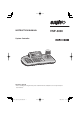
INSTRUCTION MANUAL VSP-3000 System Controller About this manual • Before installing and using this unit, please read this manual carefully. Be sure to keep it handy for later reference. 01GB_L8CSE_WA_VSP3000.
Contents Introduction Operation Precautions ........................................................ 2 Safety Cautions ................................................. 3 Main features ..................................................... 7 Accessories ....................................................... 7 Preparations Part names ......................................................... 8 Connection method ......................................... ■ Connecting to a Sanyo camera ..................
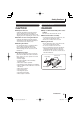
Precautions ■ For UL Users CAUTION RISK OF ELECTRIC SHOCK DO NOT OPEN CAUTION: TO REDUCE THE RISK OF ELECTRIC SHOCK, DO NOT REMOVE COVER (OR BACK). NO USER-SERVICEABLE PARTS INSIDE. REFER SERVICING TO QUALIFIED SERVICE PERSONNEL. WARNING: To reduce the risk of fire or electric shock, do not expose this appliance to rain or moisture.
Safety Cautions Main Unit WARNING ■ Never use when unit emits smoke, unusual noises, or unusual smells. Using under these abnormal conditions can cause fires and electric shock. Immediately unplug the AC adapter power plug from the outlet, confirm that the smoke stops, and then request repairs from the installer or the purchasing source. Never attempt to repair the unit on your own, as this is dangerous.
Safety Cautions Provided AC Adapter CAUTION DANGER ■ Transport with care ■ Only use with 100 to 240V power source voltage. Unplug the AC adapter power plug from the outlet, confirm that connection cables are disconnected, and transport carefully to avoid dropping the unit or subjecting it to severe shock. ■ Cautions for care or long-term disuse Unplug the AC adapter power plug from the outlet. Caring for the unit with the AC adapter connected can cause electric shock.
Safety Cautions (Continued) Provided AC Adapter WARNING ■ Use only the provided AC adapter Use the provided AC adapter. Using a different AC adapter can cause fires or electric shock, due to differences in power cord current capacity. ■ Never touch the AC adapter with wet hands This can cause electric shock. ■ Power cord Never bundle up the power cord during use. This can cause overheating, fires and electric shock.
Safety Cautions CAUTION ■ Do not connect to other equipment The provided AC adapter and power cable are exclusively for use with this unit. Connecting to other equipment can cause fires or electric shock. ■ Power cord Damaging the power cord in the following manner can cause fires or electric shock. When the power cord is damaged, consult the installer or the location of purchase.
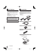
Main features Accessories • You can use the joystick to carry out Check that all accessories are included. pan, tilt and zoom operations for the camera. • RS-485 communication cable can be connected. • Password setting is available. AC adapter/power cord x 3 • North America: 1 • Europe: 1 • Great Britain: 1 Trademark Brands and product names described in this document are trademarks or registered trademarks of their respective companies. Licensed Under U.S. Patent No.
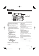
Part names ① ② Front ③ ⑩ PWR ④ ⑤ ⑥⑦ ⑧ Tx Rx ⑨ DVR: Digital video recorder ① Escape/Power button (ESC/PWR) ③ Menu display ESC: This is used to exit from the current operating menu and return to the initial screen. PWR: • When you press the button, the power turns on and the PWR indicator on the power/ communication indicator panel illuminates. The version information will be displayed in the menu display, and then the initial screen will be displayed.
Part names (continued) Rear ① ② ③ ④ ⑤ ① Power terminal (DC 12 V) ④ Program terminal (PROGRAM) Connect the accessory AC adapter to the DC terminal. This is for service use. ② USB mouse port (USB) Use commercially-available alkaline battery. ⑤ Battery compartment (DC 9 V) Connect the accessory USB cable to this port if using a DVR with a mouse function.
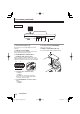
Connection method ■ Connecting to a Sanyo camera (Operation: P20) TRx (+) : A TRx (–) : B Tx1 Tx2 x TR Tx3 A B System controller AC adapter (accessory) SIDE-A 485A 485B Dome camera (sold separately) Monitor (sold separately) Preparations 01GB_L8CSE_WA_VSP3000.
Connection method (continued) ■ Connecting to a Sanyo DVR (Operation: P28) Set the protocol to “SSP” for all of the cameras being connected.
Connection method ■ Connecting to a Sanyo DVR with a mouse function (Operation: P29) (1−16) Video input terminal Camera (sold separately) Video input terminal Camera (sold separately) Monitor (sold separately) DVR with mouse function (sold separately) T USB cable (accessory) System controller A AC adapter (accessory) B TRx (+) : A TRx (–) : B Preparations 01GB_L8CSE_WA_VSP3000.
Menu settings ■ Main menu steps Press the SUB MENU/MAIN MENU button. The MAIN MENU screen appears in the menu display and you are prompted to enter the password. No password is set initially, so simply press the ENT button. “1.VER: X.XX” will then be displayed. [ MAIN MENU ] PASSWORD[ ---- ] [ MAIN MENU ] OK [ñ MAIN MENU 1.VER: X.XX ] To set a password, refer to “À Password setting” in the menu setting section. (P18) Use the joystick to switch menu displays.
Menu settings 1 2 Language setting The only available language for menus is English. No setting is neccessary. When “ENGLISH” is displayed, press the ENT button or the ESC/PWR button to return to the MAIN MENU screen. ó MAIN MENU [ñ ] 3.LANGUAGE SET · Title setting This sets a title (maximum 16 characters) for the system controller. (Default setting: VSP-3000 ➝ Example: SAN 1001) the joystick up or down to 1 Move select “4. TITLE SET”. ó MAIN MENU [ñ 4.TITLE SET ] · the joystick to the right.
Menu settings (continued) 3 Control ID setting 4 Termination setting If using more than one system controller, change the addresses for each of them. The addresses can be assigned to a number within the range of 0 to 4. (Default setting: 0) Set the termination for the system controller. (Default setting: ON) the joystick up or down to 1 Move select “5. CONTROL ID”. the joystick to the left or right 2 Move to set the termination. ó MAIN MENU †] [ñ 5.
Menu settings 5 6 Sleep setting You can set the system controller to turn off automatically if it is not operated for a certain period of time. When this is done, a moving “SLEEP MODE” display will appear in the menu display. (Default setting: OFF) the joystick up or down to 1 Move select “7. SLEEP”. ó MAIN MENU [ñ 7.SLEEP: OFF †] the joystick to the left or 2 Move right to select the time (Example: 1 (HOUR)). This sets the buzzer when the system controller is operated.
Menu settings (continued) 7 8 Backlight setting This sets the brightness of the system controller’s menu display screen. (Default setting: OFF) the joystick up or down to 1 Move select “9. BACKLIGHT”. ó MAIN MENU †] [ñ 9.BACKLIGHT:OFF the joystick to the left or right 2 Move to set the backlight (Example: AUTO). ó MAIN MENU í] [ñ 9.
Menu settings 9 10 DVR link setting The camera images from the DVR which is connected to the system controller switch in line with the camera selection. (Default setting: ON) the joystick up or down to 1 Move select “11. DVR LINK”. ó MAIN MENU í] [ñ 11.DVR LINK: ON the joystick to the left or right 2 Move to set the DVR connection (Example: OFF). ó MAIN MENU †] [ñ 11.DVR LINK: OFF Available settings: ON, OFF the joystick up or down to 3 Move select “14.
Menu settings (continued) 11 Default setting This returns all settings to the default settings that were in place at the time of shipment from the factory. the joystick up or down to 1 Move select “13. FACTORY SET”, and then move the joystick to the right. ó MAIN MENU [ñ ] 13.FACTORY SET · the joystick to the left or right 2 Move to select “YES”, and then press the ENT button.
Camera settings ■ Camera setup steps While pressing the SHIFT/FUNC. button, press the SUB MENU/MAIN MENU button. “CAM SETUP001” will be displayed in the menu display and you will be prompted to enter the password. + [ CAM SETUP001 ] PASSWORD[ ---- ] To set a password, refer to “À Password setting” in the menu setting section. (P18) No password is set initially, so simply press the ENT button. “1. ADDRESS: 001 (blink)” will be displayed. [ CAM SETUP001 ] OK [ñCAM SETUP001†] 1.
Camera settings (continued) 1 Address setting This selects the camera address. All settings other than this one will be applied to the selected address. (Default setting: 001) the joystick up or down to 1 Move select “1. ADDRESS”. [ñCAM SETUP001†] 1.ADDRESS: 001 the joystick to the left or right 2 Move to select the address, and then press the ENT button. [ñCAM SETUP001†] 1.ADDRESS: 001 [ñCAM SETUP255†] 1.ADDRESS: 255 The address can also be selected using the numeric buttons.
Camera settings 3 4 Baud rate setting This sets the communication speed. (Default setting: 19.2 Kbps) the joystick up or down to 1 Move select “3. BAUDRATE”. óCAM SETUP001◆] [ñ 3.BAUDRATE:19.2k the joystick to the left or right 2 Move to select the communication speed. Available settings: 2.4k, 4.8k, 9.6k, 19.2k, 38.4k, 57.6k the joystick up or down to 3 Move select “7. SAVE”, and then move the joystick to the right. “OK” will be displayed and the settings will be saved. [ó ñCAM SETUP001 ] 7.
Camera settings (continued) 5 DVR address and channel setting This assigns the DVR address and channel number to the selected camera. For details, refer to “Camera address numbers (default value)”. See page 31. the joystick up or down to 1 Move select “6. DVR”. The “01” setting assigned to the first DVR will flash. óCAM SETUP001†] [ñ 6.DVR:01 CH:01 the joystick to the left or 2 Move right to select the address for the connected DVR (Example: 03), and then press the ENT button.
Camera operations ■ Operating the camera from the system controller Press the button corresponding to the number of the camera to be operated (Example: 2), and then press the ENT button. SANYO SSP 19.2k CAM:001 D1 CH01 Camera 2 will be selected and the channel connected to DVR 01 will change to 2. For details, refer to “Camera address numbers (default value)”. See page 31. SANYO SSP 19.2k CAM:2– D SANYO SSP 19.
Camera operations (continued) ■ Operating the camera by changing FOCUS NEAR: Adjusts the focus to the nearest object. FOCUS FAR: Adjusts the focus to the furthest object. GO PRESET P: The camera will move to the preset position which has been recorded. For details, refer to “Preset position retrieval operation”. See page 26. MEM.PRESET: ?: Lets you record an object into a preset setting. For details, refer to “Preset memory operations”. See page 26.
Camera operations ■ Auxiliary function operation ■ Preset memory operations Transmits AUX ON/OFF commands to the selected cameras. For details, refer to “List of auxiliary commands for Sanyo cameras”. (P30) Records preset positions into the cameras. First use the joystick or some other method to select a preset position for the camera. 1 “AUX ON” will be displayed. Press the AUX button. If the AUX button is pressed once more, the display changes to “AUX OFF”.
Camera operations (continued) ■ Retrieving pan, sequence and tour operations recorded in a PTZ camera You can select preset pan, sequence and tour operations so that these operations can be carried out. This operation is limited to the following camera models which already contain preset operations. • VCC-9500/9600/9700/9800 series If you enter a number outside the range of 1 to 4, “error” will be displayed, so re-enter the number. PAN PATTERN: error B Sequence operation pressing the SHIFT/FUNC.
DVR operation ■ Switching the DVR screen display The only DVR function that can be operated from the system controller is the screen display switching function. The monitor screen can be switched between multi-screen, quad-screen or single-screen display by pressing the following buttons. 02 (Single-screen display) SANYO SSP 19.2k CAM:001 D1 CH01 01 02 03 04 05 06 07 08 09 10 11 12 13 14 15 16 01 02 03 04 05 06 07 08 09 (Multi-screen display) SANYO MULTI SSP 19.
Operating a DVR with mouse function Use the accessory USB cable to connect a DVR with mouse function (such as the HD-8000) to the USB mouse port at the rear of the system controller. For details on the connection method, refer to P12. the mouse ( ) button. 1 Press “MOUSE MODE” will be displayed, and you can then use the joystick to move the cursor. Camera operations cannot be carried out at this time. SANYO SSP 19.2k MOUSE MODE L button: Left click R button: Right click the mouse button once more.
Appendices ■ List of auxiliary commands for Sanyo cameras The commands are examples of commands for the VCC-9500/9600/9700/9800 series. Auxiliary command ON OFF Operation 1 Switch to Color Mode Pan/Tilt control 1 Switches a day/night camera to color mode. 2 Switch to B/W Mode Pan/Tilt control 2 Switches a day/night camera to black & white mode. 3 Switch to Day/Night Auto Mode Pan/Tilt control 3 Switches a day/night camera to day/ night automatic mode.
Appendices (continued) ■ Camera address numbers (default value) Camera address Connected DVR Connected channel No. CAM No. 1 2 3 4 5 6 7 8 9 10 11 12 13 14 15 16 17 18 19 20 21 22 23 24 25 26 27 28 29 30 31 32 DVR 1 1 1 1 1 1 1 1 1 1 1 1 1 1 1 1 2 2 2 2 2 2 2 2 2 2 2 2 2 2 2 2 CH 1 2 3 4 5 6 7 8 9 10 11 12 13 14 15 16 1 2 3 4 5 6 7 8 9 10 11 12 13 14 15 16 CAM No.
Specifications Communication format RS485, RS-422 Keyboard 29 keys Joystick 3-axis joystick (pan / tilt / zoom) Control communication terminal Tx1, Tx2, Tx3, TRx Protocol SSP, H-SSP, Pelco-D USB mouse port Compatible with DVRs with mouse function Communication speed 2400, 4800, 9600, 19200, 38400, 57600 bps Max.
SANYO Electric Co., Ltd. 01GB_L8CSE_WA_VSP3000.