
User's Manual

Page 4 of 8
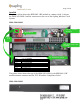
HPB-24G-1 Connectors
Installed
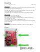
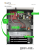
The picture on the next page shows the HPB-24G-1 RF module in a repeater. It
shows the SMA-1SR-G0000-1 and the connectors to the rest of the Sapling
Wireless Clock System.
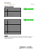
P1 OPERATING CONNECTOR
PIN 1
5 VOLTS
PIN 2
GROUND
PIN 3
PPS OUT
PIN 4
TXD
PIN 5
RXD
PIN 6
MSTR/SLV
PIN 7
STBY
PIN 8
NO CONNECTION
* PIN 1 IS SQUARE PAD.
P2 PROGRAMMING CONNECTOR
PIN 1
TDO/TDI
PIN 2
3.3 VOLTS
PIN 3
TDI
PIN 4
3.3 VOLTS
PIN 5
TMS
PIN 6
NO CONNECTION
PIN 7
TCLK
PIN 8
TEST
PIN 9
GROUND
PIN 10
NO CONNECTION
PIN 11
RST
PIN 12
TXD
PIN 13
SHIELD
PIN 14
RXD
* PIN 1 IS SQUARE PAD.
P2 PROGRAMMING
P1 POWER & DATA