
User's Manual

Page 7 of 8
Installed
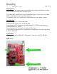
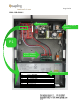
The picture below shows the HPB-24G-1 RF module in a master clock. It shows
the SMA-3S0-G008-1 and the connectors to the rest of the Sapling Wireless Clock
System.
SMA-3S0-G008-1
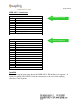
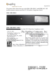
The picture below shows the top of the SMA-3S0-G008-1 with HPB-24G-1 RF
module antenna connector and the FCC ID and the Compliance Label.
SMA-3S0-G008-1
FCC ID: R73HPB-24G-1
HPB-24G-1
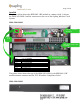
P1
P1 OPERATING CONNECTOR
PIN 1
5 VOLTS RED WIRE
PIN 2
GROUND BLACK WIRE
PIN 3
PPS OUT
PIN 4
TXD ORANGE WIRE
PIN 5
RXD VIOLET WIRE
PIN 6
MSTR/SLV WHITE WIRE
PIN 7
STBY
PIN 8
NO CONNECTION
* PIN 1 IS SQUARE PAD.
P1 POWER & DATA
5 VOLT POWER
SUPPLY
RELAY & CONTROL
BOARD