User’s Manual Sapphire Pure Platinum A85XT AMD A85X chipset for FM2 Socket Mainboard TRADEMARK All products and company names are trademarks or registered trademarks of their respective holders. These specifications are subject to change without notice. Manual Revision 1.
Federal Communications Commission (FCC) Statement This device has been tested and found to comply with the limits for a Class B digital device, pursuant to Part 15 of FCC Rules. These limits are designed to provide reasonable protection against harmful interference in a residential installation.
Table of Contents Chapter 1 Introduction ...................................................................... 1 1-1 Mainboard Specifications ........................................................... 1 1-2 Package Contents ..................................................................... 5 1-3 Mainboard Layout ...................................................................... 6 Chapter 2 Installation .......................................................................
Reset and Power Button .......................................................... 24 2-11 Dual BIOS Switch ................................................................... 25 Chapter 3 Configuring the BIOS .................................................... 27 3-1 Select Boot Device .................................................................. 27 3-2 Enter BIOS Setup .................................................................... 27 3-3 Main Menu ..............................................
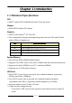
Chapter 1 Introduction 1‐1 Mainboard Specifications CPU AMD® socket FM2 A10/A8/A6/A4 series Trinity processor Chipset AMD A85X (Hudson-D4) chipset Graphics AMD on-die RadeonTM HD 7xxx GPU Four independent displays and supporting triple view with VGA and DVI and either HDMI or Diskplay port Port VGA DVI-D HDMI 1.4a Display Port 1.
SATA Ports Seven SATA3 ports with 6Gb/s data transfer rate Supports integrated RAID 0, RAID 1, RAID 5 and RAID 10 Supports AHCI (Advanced Host Controller Interface) Onboard LAN One Gigabit Ethernet from Realtek® RTL8111F Gigabit controller Bluetooth Atheros AR3011 is a highly integrated, all-CMOS, single chip with Bluetooth® 2.
4 x USB 2.0 ports 1 x Bluetooth 1 x Optical S/PDIF Out connector 1 x HDMI port 1 x Display port 1 x VGA port 1 x DVI-D port 1 x RJ45 LAN port 2 x USB 3.0 ports 6 Audio jacks Internal I/O Connectors 1 x 24-pin ATX power connector 1 x 8-pin ATX 12V power connector 7 x SATA3 connectors 4 x USB2.0 headers 2 x USB3.
Supports Windows based OC utility “Trixx” and Win7 HW monitor gadget tool IR digital PWM design (VCore and VDIMM) Supports additional DVI card (optional) Form Factor ATX form factor of 305mm x 245mm Operating systems: Supports Windows Vista, Windows 7 and Windows 8 ~4~
1‐2 Package Contents Your Sapphire mainboard comes with the following accessories. 1. Mainboard 2. I/O Shield 3. Quick Installation Guide 4. Driver DVD 5. USB3.0 Front Panel Cable (Optional) 6. SATA Data Cable *6 7.
1‐3 Mainboard Layout The following figure shows the location of components on the mainboard. following page for description. Note: Picture is for reference only, actual board may be slightly different.
Item Component description 1 AMD CPU Socket FM2 2 AMD A85X (Hudon‐D4) Chip 3 DDR3 DIMM Slots 1‐4 4 PCI‐E 2.0 x16 Slots *2 5 PCI‐E 2.0 x4 Slots *1 6 PCI‐E 2.0 x1 Slot *2 7 PCI Slot *2 8 Mini PCI‐E x1/mSATA Connector 9 24‐Pin ATX Power Connector 10 8‐pin ATX_12V Power Connector 11 SATA3 Connectors *7 12 Front Panel Header 13 USB 2.0 Header *4 14 USB 3.
I/O Back Panel The I/O back panel for this mainboard is shown below. When installing the mainboard into the computer case, use the bundled I/O shield to protect the back panel. 1. PS/2 Keyboard/Mouse Port This connector is used for a keyboard or mouse. You can plug a PS/2 keyboard or mouse directly into this connector. 2. USB 2.
8. DVI-D Port The DVI-D (Digital Visual Interface-Digital) port provides a high-speed digital interconnection between the computer and its display device. Connect a monitor that supports DVI-D connection to this port. The DVI-D port does not support analogue VGA monitors using a passive DVI to VGA adapter. Multi Display Configurations: This mainboard provides four ports for video output: Display port, HDMI, DVI-D, and VGA. Also provides an optional DVI card.
9. USB 3.0 ports (two) USB 3.0 ports are backward compatible with USB 2.0 devices. Supports data transfer rates up to 4.8Gb/s (SuperSpeed). 10. Audio ports This mainboard provides 2, 6 or 8 channel audio. It is easy to differentiate between the audio functions by referring to the color of the jacks.
Chapter 2 Installation 2‐1 Before You Begin Please take note of all precautions before you install anything on to the mainboard or change any of the mainboard settings. Turn off the power to your system and discharge your body’s static electric charge by touching a grounded surface—for example, the metal surface of the power supply—before performing any hardware procedure.
2‐4 Installing the CPU and Cooler Follow the steps below to install the CPU & cooler correctly. 1. Open the socket lever and rise to a 90 degree angle. 1 2. Align the CPU pin one (small triangle marking) and gently insert the CPU into the socket then close the socket lever. Note: Apply some thermal paste on surface of CPU for better heat dispersion. 2 3. Place the cooler on the CPU. Engage one side of the clip onto the CPU mount first then press down the other side of the clip. 4.
2‐5 Installing System Memory This mainboard has four 240-pin DIMM sockets for DDR3 memory. These slots support 1GB, 2GB, 4GB and 8GB DDR3 DIMMs up to a maximum 32GB. Make sure that you install memory modules of the same type and density in the different channel DIMM slots for Dual-Channel mode. There must be at least one memory bank populated to ensure normal operation and you can insert the memory module into any of the DIMM slots.
2‐6 Installing Expansion Cards The mainboard provides two PCI Express 2.0 x16 slots, one PCI Express 2.0 x4 slot, two PCI Express 2.0 x1 slots, two PCI slots and one Mini PCI-E x1 or mSATA slot. PCIE1_ X4 PCI‐E2.0 x4 slot (with x4 link, Black) PCIE2_X16/X8 PCI‐E2.0 x16 slot (with x16/x8 link, Blue) PCIE3_X1 PCI‐E2.0 x1 slot (with x1 link, Black) PE6 Mini PCI‐E2.0 x1 or mSATA slot PCIE4_X1 PCI‐E2.0 x1 slot (with x1 link, Black) PCIE5_X8 PCI‐E2.
The design of this motherboard supports AMD CrossFireTM technology for support of multiple graphic cards. Please refer to the location of slots and recommended configuration table for PCI-E operating mode to get the best performance possible.
Installing additional DVI card This mainboard can be provided with an optional DVI card. This allows you to connect to an additional display. Please refer to the following setups for installing DVI card: 1. Connect an additional monitor cable to the DVI port of the back panel of your mainboard and make sure the monitor is plugged in and turned on. 2. Insert the optional DVI card into the PCIE2_X16/X8 slot and ensure the card is properly seated on the slot. 3.
2‐7 Connecting Cables This section takes you through all the necessary connections on the mainboard. Connecting Power Supply Cables 24-pin ATX Power PW1 is the main power supply connector. Make sure that the power supply cable pins are properly aligned with the connector on the mainboard. Firmly plug the power supply cable into the connector and make sure it is secure. Note: If you’d like to use 20-pin ATX power supply, please plug in your power supply cable aligned with pins 1 & 13.
Connecting Serial ATA (SATA) Cables SATA cables support the Serial ATA protocol. Each cable can be used to connect one SATA drive to the mainboard. The S1 to S5 connectors (total 7 ports) are SATA3 connectors and works at speeds of up to 6G/s and support RAID 0, 1, 10, 5 functions.
Connecting to the Internal Headers and Connectors Front Panel Header The front panel header on this motherboard is used to connect the front panel switches and LEDs. PWR_LED Attach the front panel power LED cable to these two pins of the connector. The Power LED indicates the system’s status. System Status On Off S3 S4 Power LED indicates The LED is on The LED is off The LED will blink The LED is off PW_ON Attach the power button cable from the case to these two pins.
USB2.0 Headers This mainboard contains four (4) USB 2.0 ports that are exposed on the rear panel of the chassis. This mainboard also contains three 10-pin onboard header connectors that can be used to connect to four (4) external USB 2.0 devices. Refer to the following steps: 1. Secure the bracket to either the front or rear panel of your chassis (not all chassis are equipped with the front panel option). 2. Connect the cable(s) to the USB 2.0 header on the mainboard.
CFPA Header This header allows you to connect the front panel audio. The audio connector supports HD audio standard. S/PDIF Header This header is used to connect S/PDIF (Sony & Philips Digital Interconnect Format) interface for digital audio transmission. Serial Port Header The Serial port header (COM1) can provide one serial port via an optional COM port cable. Note: The pin definition of header and standard DB9 male pin out is different.
Fan Headers There are six fan headers (CPUFAN, SYSFAN, SYSFAN1, PWRFAN, CHAFAN, and AUXFAN) on the motherboard. Three of these fans (CPUFAN, PWRFAN, and CHAFAN) can be speed detected/controlled and displayed in the Hardware Health Configuration section of the CMOS Setup. The fans are automatically turned off after the system enters S3, S4 or S5 mode. CPUFAN PWRFAN SYSFAN1 CPUFAN Note: The CPU fan cable can be either a 3-pin or a 4-pin connector.
2‐8 Diagnostics LED This mainboard provides a two-digit POST code to show why the system may be failing to boot. It is useful during a troubleshooting situation. This Debug LED will also display the current CPU temperature after the system has fully booted into the operating system. Please find a list of debug codes at the end of this manual. Debug LED 2‐9 LED Status Indicators This mainboard provides three LEDs to indicate the system’s status.
2‐10 Onboard Buttons These onboard buttons include RESET CMOS, RESET and POWER, which allow you to easily clear the CMOS, reset the system and turn on/off the system. Reset CMOS Button The mainboard uses the CMOS RAM to store some of the system configuration. The CMOS can be cleared by pressing the RESET CMOS button. Reset and Power Button These onboard buttons allow you to easily turn on/off the system and allow for easy debugging and testing of the system during troubleshooting situations.
2‐11 Dual BIOS Switch Recover BIOS: This mainboard includes dual onboard BIOS, (Primary and Secondary BIOS), When the primary BIOS is corrupted or has failed, the system will automatically switch to secondary BIOS to boot and ensure normal system operation. Please refer to the following steps: 1. Turn on the system power. 2. The system can detect and automatically switch to the secondary BIOS in order to boot when the primary BIOS has failed,, despite the BIOS switch position. 3.
Flash BIOS: If the primary (secondary) BIOS is corrupted or outdated, you can use the USB pen drive or AMI Windows flash utility to do flashing BIOS process to recover the primary (secondary) BIOS. Flash primary BIOS: Make sure the BIOS select switch is at “P” position and power on. Flash the BIOS using either USB pen drive under DOS or AMI Windows flash utility under Windows. Flash secondary BIOS: Make sure the BIOS select switch is at “S” position and power on.
Chapter 3 Configuring the BIOS This chapter provides information on the BIOS Setup program and allows you to configure the system for optimum use. 3‐1 Select Boot Device Select Boot Device Menu allows you to set the first boot device without entering BIOS Setup. During Power On Self-Test (POST), you can press the key to enter select boot device menu. The system will directly boot from the device configured in Boot Menu.
upon the bottom of the display during Power On Self-Test (POST). Press F1 to continue, DEL to enter Setup. Pressing Del takes you to the BIOS Setup Utility. Note1: It is strongly recommended that you do not change the default BIOS settings. Changing some settings could damage your computer. Note2: The BIOS options in this manual are for reference only. BIOS screens in manuals are usually the first BIOS version when the board is released and may be different from your purchased motherboard.
3‐3 Main Menu When entering the BIOS Setup Utility, the main menu screen appears. This main menu includes the system overview and displays the basic system configuration, such as BIOS information, memory size and system date/time. BIOS Information BIOS Vendor Core Version Compliancy Project Version Build Date and Time American Megatrends 4.6.5.3 UEFI 2.3; PI 1.2 F285X 0.
Access Level This item is used to limit the user access level. 3‐4 Performance Menu The Performance menu allows you to specify your settings for CPU, memory, voltage control and overclocking. Press to display the configuration options. CPU Host Clock (Mhz) CPU Ratio GPU Clock CPU NB Frequency (MHz) Memory Configuration Voltage Configuration 100 [Auto] [Auto] [Auto] 1.456 1.232 1.096 1.528 100 3827 16384 1600 CPU Host Clock Allows you to select the CPU Host Clock.
Memory Configuration Memory Clock CAS Latency RAS# to CAS# Delay Row Precharge Time RAS# Active Time Write Recovery Time Row Refresh Cycle Time Write to Read Delay Active to Active Delay Read CAS# Precharge Four Active Windows Delay Row Cycle Time Refresh Rate Command Rate DDR3‐1600 (tCL) 11 (tRCD) 11 (tRP) 12 (tRAS) 28 (tWR) 12 (tRFC) 160 (tWTR) 6 (tRRD) 5 (tRTP) 6 (tFAW) 24 (tRC) 39 (tREF) 7.8 2 [Auto] [Auto] [Auto] [Auto] [Auto] [Auto] [Auto] [Auto] [Auto] [Auto] [Auto] [Auto] [7.8 us] [Auto] 1.
Options: Auto(28), 8 ~ 40. Write Recovery Time (tWR) Set the internal Write to Read recovery time. Options: Auto(12), 5 ~ 16. Row Refresh Cycle Time (tRFC) Set the minimum refresh recovery time. Options: Auto(160), 90ns, 110ns, 160ns, 300ns, 350ns. Write to Read Delay (tWTR) Set the internal Write to Read command delay. Options: Auto(6), 4 ~ 9. Active to Active Delay (tRRD) Set the Row Active to Row Active delay. Options: Auto(5), 4 ~ 9. Read CAS# Precharge (tRTP) Set the Read to Precharge delay.
Voltage Configuration Voltage Configuration CPU Loadline APU Voltage Mode APU Voltage FCH DIMM DQ Voltage DIMM CA Voltage VDDR VDDP VDDA DIMM Voltage DIMM VTT CPU Loadline [Enabled] [Offset Mode] [+0.00000V] [1.10V] [+0.00V] [+0.00V] [1.20V] [1.20V] [2.50V] [1.50V] [+0.00V] 1.456 1.232 1.096 1.528 100 3827 16384 1600 46 41 28 CPU Loadline Loadline Control function is a safety measure to protect the CPU. Options: Enabled, Disabled. APU Voltage Mode Allows you to select the APU voltage mode.
DIMM CA Voltage Allows you to adjust the DIMM CA of DIMM Slot voltage. Options: 0.00V ~ 0.64V in 0.01V increments. VDDR Allows you to adjust the VDDR voltage. Options: 1.20V ~1.83V in 0.01V increments. VDDP Allows you to adjust the PCI Express I/O ring voltage. Options: 1.20V ~1.83V in 0.01V increments. VDDA Allows you to adjust the filtered PLL voltage. Options: 2.50V ~3.31V in 0.01V increments. DIMM Voltage Allows you to adjust the DIMM Slot voltage. Options: Auto, 1.50V ~2.30V in 0.01V increments.
3‐5 Advanced Menu The Advanced menu items allow you to change the settings for the CPU, USB and other system devices. Press to display the configuration options. S5 RTC Wake Settings ACPI Settings CPU Configuration SATA Configuration USB Configuration Super IO Configuration H/W Monitor Onboard Device 1.456 1.232 1.096 1.
S5 RTC Wake Settings Wake systems with Fixed Time [Disabled] Make system with Dynamic Time [Disabled] Enable or Disable System wake on alarm event. When enabled, the system will wake on the hr::min::sec specified. 1.456 1.232 1.096 1.528 100 3827 16384 1600 46 41 28 Wake system with Fixed Time Enable or disable system wake on alarm event. When enabled, system will wake on the hr:min:sec specified. Options: Enabled, Disabled.
ACPI Settings ACPI Settings Enable Hibernation ACPI Sleep State EuP Function Restore AC Power Loss [Enabled] [S3 only (Suspend to RAM)] [Disabled] [Power Off] 1.456 1.232 1.096 1.528 100 3827 16384 1600 Enables or Disables system ability to Hibernate (OS/S4 Sleep Sate). This option may be not effective with some OS. 46 41 28 Enable Hibernation Enables system ability to Hibernate (OS/S4 Sleep Sate). This option may be not effective with some OS. Options: Enabled, Disabled.
CPU Configuration CPU Configuration CPU Configuration Module Version: 4.6.5.1 TrinityPI 012 AGESA Version: 1.1.0.2 AMD Cool’n’ Quiet PSTATE Adjustment PPC Adjustment NX Mode SVM Mode AMD Core Performance Boost C6 Mode CPU Information [Enabled] [PState 0] [PState 0] [Enabled] [Enabled] [Auto] [Enabled] 1.456 1.232 1.096 1.528 100 3827 16384 1600 46 41 28 AMD Cool’n’ Quiet Cool'n'Quiet is a CPU speed throttling and power saving technology by AMD. Options: Enabled, Disabled.
AMD Core Performance Boost Allows you to disable AMD Core Performance Boost. Options: Auto, Disabled. C6 Mode Allows you to select C6 State for processor. Options: Enabled, Disabled. CPU Information Displays the CPU related information.
SATA Configuration SATA Configuration OnChip SATA Type 6 AHCI/RAID Port [AHCI] [Disabled] SATA Port 0 (AHCI Mode) SATA Port 1 (AHCI Mode) SATA Port 2 (AHCI Mode) SATA Port 3 (AHCI Mode) SATA Port 4 (IDE Mode) SATA Port 5 (IDE Mode) SATA Port 6 (IDE Mode) mSATA Port (IDE Mode) ESATA PORT on PORT0 ESATA PORT on PORT1 ESATA PORT on PORT2 ESATA PORT on PORT3 ESATA PORT on PORT4 ESATA PORT on PORT5 ESATA PORT on PORT6 ST3250318AS (250.
USB Configuration Enables Legacy USB support. AUTO option disables legacy support if no USB devices are connected. DISABLE option will keep USB devices available only for USB Configuration USB Devices: 1 Keyboard, 1 Mouse Legacy USB Support USB3.0 Support XHCI Hand‐off EHCI Hand‐off [Enabled] [Enabled] [Enabled] [Disabled] USB Hardware delays and time‐outs: USB transfer time‐out [1 sec] Device reset time‐out [10 sec] Device power‐up delay [Auto] 1.456 1.232 1.096 1.
USB transfer time-out The time-out value for control, bulk, and interrupt transfers. Options: 1 sec, 5 sec, 10 sec, 20 sec. Device reset time-out Sets USB mass storage devices start unit command time-out. Options: 10 sec, 20 sec, 30 sec, 40 sec. Device power-up delay Maximum time the device will take before it properly reports itself to the Host controller. ‘Auto’ uses default values; for a Root port it is 100ms, for a Hub port the delay is taken from Hub descriptor. Options: Auto, Manual.
Change Settings Select an optimal setting for super I/O device. Options: Auto, IO=3F8H; IRQ=4; IO=3F8h; IRQ=3,4,5,6,7,10,11,12; IO=2F8h; IRQ=3,4,5,6,7,10,11,12; IO=3E8h; IRQ=3,4,5,6,7,10,11,12; IO=2E8h; IRQ=3,4,5,6,7,10,11,12 H/W Monitor PC Health Status Smart Fan Configuration APU Temperature VREG Temperature System Temperature APU Fan Speed Power Fan Speed Chassis Fan Speed VCC3V APU APU_NB FCH DIMM APU_VDDR APU_VDDP VSB3V VBAT : +48 C : +45 C : +29 C : 2018 RPM : N/A : N/A : +3.136 V : +1.456 V : +1.
Smart Fan Configuration SmartFan Configuration CPU Fan Type CPU Fan Mode Setting Temperature Limit of Highest Temperature Limit of Lowest Fan Highest setting Fan Lowest setting Power Fan Mode Setting Temperature Limit of Highest Temperature Limit of Lowest Fan Highest setting Fan Lowest setting Chassis Fan Mode Setting Temperature Limit of Highest Temperature Limit of Lowest Fan Highest setting Fan Lowest setting [PWM FAN (4 pin)] [SmartFan] 060 030 100 050 [SmartFan] 060 030 100 050 [SmartFan] 060 030 10
Onboard Device HD Audio Azaila Device Onboard LAN (Realtek) C80P Show CPU Temperature PS2 Port Type [Enabled] [Enabled] [Enabled] [Auto] 1.456 1.232 1.096 1.528 100 3827 16384 1600 HD Audio Azaila Device Enables the onboard High Definition Audio controller. Options: Enabled, Disabled. Onboard LAN (Realtek) Enables the onboard Giga Lan function by Realtek for LAN. Options: Enabled, Disabled C80P Show CPU Temperature Enables the onboard POST Port LED to display CPU temperature.
3‐6 Chipset Menu The chipset menu items allow you to change the advanced chipset settings. Press to display the sub-menu. Enable/Disable IOMMU support North Bridge Configuration IOMMU [Enabled] GFX Configuration Memory Information Total Memory: 16368 MB (DDR3) DIMM Information 1.456 1.232 1.096 1.528 100 3827 16384 1600 46 41 28 IOMMU Enables or disable the IOMMU support. Options: Enabled, Disabled.
PSPP Policy Allows you to select PCIe speed power policy. Options: Disabled, Performance, Balanced-High, Balanced-Low, Power Saving. Dual-link DVI Card Support Allows you to enable or disable the Dual-link DVI card support. Options: Disabled, Enabled. DIMM Information Displays the CPU related information.
3‐7 Boot Menu The Boot menu is used to configure the boot settings and the boot priority. Number of seconds to wait for setup activation key. 65535(0xFFFF) means indefinite waiting. Boot Configuration Setup Prompt Timeout Bootup NumLock State 1 [On] Boot Option Priorities Boot Option #1 Boot Option #2 [P1: DVDRW SATA 2…] [P0: ST3250318AS …] CD/DVD ROM Drive BBS Priorities Hard Drive BBS Priorities CSM Parameters 1.456 1.232 1.096 1.
CSM Parameters Launch CSM This option controls if CSM will be launched. Options: Auto, Always, Never. Boot option filter This option controls what devices system can boot to UEFI or Legacy. Options: UEFI and Legacy, Legacy only, UEFI only. Launch PXE OpROM policy This option controls the execution of UEFI and Legacy PXE OpROM. Options: Do not launch, Legacy only, UEFI only. Launch Storage OpROM policy This option controls the execution of UEFI and Legacy Storage OpROM.
3‐8 Security Menu The Security menu allows you to change the system security settings. Password Description If ONLY the Administrator’s password is set, then this only limits access to Setup and is only asked for when entering Setup. If ONLY the User’s password is set, then this is a power on password and must be entered to boot or enter setup. In Setup the user will have Administrator rights. The password must be in the following range: Minimum length 3 Maximum length 20 Set setup Administrator Password.
3‐9 Save & Exit Menu The Save & Exit menu allows you to load the optimal default values for BIOS, and save or discard your changes to the BIOS items. Save Changes and Reset Discard Changes and Reset Reset the system after saving the changes.
Boot Override This group of functions includes a list, each of them corresponding to one device within the boot order. Select a drive to immediately boot that device regardless of the current boot order. S_BIOS Flash Utility This utility allows you to update the system BIOS in embedded BIOS. Please refer to "4-4 S_BIOS Flash Utility" for details. Flash Primary BIOS (Primary <- Secondary) This item allows you to copy the Secondary BIOS to Primary BIOS.
Chapter 4 Driver Installation After the operating system has been installed, you need to install drivers for this mainboard. The support DVD that came with the motherboard contains necessary drivers and useful utilities that enhance the motherboard features. 4‐1 Driver Install Insert the bundled driver DVD into your optical drive and the main menu will be displayed on your PC screen. Click each item button and select the item you want to install.
4‐2 TRIXX Utility TRIXX is a simple and easy-to-use utility that allows users to adjust system settings for overclocking in a Windows environment. The TRIXX utility includes three configurations for frequency, voltage and hardware monitoring. To install TRIXX Utility, run it from the Sapphire Utility page from the bundled DVD. A TRIXX Utility shortcut will be created on the Desktop. Display current CPU information Adjust frequency for CPU. Adjust voltage for CPU, DIMM etc.
4‐3 Hardware monitor gadget This Hardware monitor gadget directly appears in windows screen after TriXX installation is completed. It can be used to help keep track of temperatures of CPU, System and fan speed of CPU, System and voltages of CPU, System. Displays hardware monitor temperature. Displays fan speeds. Displays voltages of system.
4‐4 S_BIOS Flash Utility This mainboard provides a BIOS update tool. The S_BIOS allows you to update the system BIOS without having to enter MS-DOS or Windows environment. Embedded in the BIOS, the S_BIOS is simple and easy-to-use utility to flash BIOS. Refer to the following steps for S_BIOS Flash. Setp1: Enter BIOS setup screen, select “S_BIOS Flash Utility” item from “Exit” tab.
Setp3: To Update BIOS form Drive, select the BIOS update file and press to start update. If the BIOS file stored in USB device, please must first insert USB device before turning on the system and make sure the BIOS update file matches your mainboard model.
Setp4: The update BIOS processing screen appears. Setp5: The BIOS update is completed. Please press any key to restart the system.
Setp6: Save BIOS to Drive, allows you to save the current BIOS file. If the BIOS file stored in USB device, please must first insert USB device before turning on the system. Setp7: To Save BIOS to Drive, Select the stored location and press to start saving BIOS file.
Setp8: After saving BIOS file is completed. Select to return “Exit” tab of BIOS setup.
Chapter 5 POST Code This chapter provides the Aptio POST Codes List for the mainboard during the BIOS pre-boot process. The POST Codes are displayed on the Debug LED readout located directly onboard the mainboard.
05 OEM initialization before microcode loading 06 Microcode loading 07 AP initialization after microcode loading 08 North Bridge initialization after microcode loading 09 South Bridge initialization after microcode loading 0A OEM initialization after microcode loading 0B Cache initialization SEC Error Codes 0C – 0D Reserved for future AMI SEC error codes 0E Microcode not found 0F Microcode not loaded PEI Phase Status Code Progress Codes 10 11 12– 14 15 16 17 18 19 1A 1B 1C 1D – 2A 2B 2C 2D 2E 2F 30 31 32
3C 3D 3E 3F‐4E 4F PEI Error Codes 50 51 52 Post‐Memory South Bridge initialization (South Bridge module specific) Post‐Memory South Bridge initialization (South Bridge module specific) Post‐Memory South Bridge initialization (South Bridge module specific) OEM post memory initialization codes DXE IPL is started Memory initialization error. Invalid memory type or incompatible memory speed Memory initialization error. SPD reading has failed Memory initialization error.
DXE Phase Status Code 60 61 62 63 64 65 66 67 68 69 6A 6B 6C 6D 6E 6F 70 71 72 73 74 75 76 77 78 79 7A – 7F 80 – 8F 90 91 92 93 94 95 96 97 98 99 9A 9B 9C 9D 9E – 9F A0 Description DXE Core is started NVRAM initialization Installation of the South Bridge Runtime Services CPU DXE initialization is started CPU DXE initialization (CPU module specific) CPU DXE initialization (CPU module specific) CPU DXE initialization (CPU module specific) CPU DXE initialization (CPU module specific) PCI host bridge initial
A1 IDE Reset A2 IDE Detect A3 IDE Enable A4 SCSI initialization is started A5 SCSI Reset A6 SCSI Detect A7 SCSI Enable A8 Setup Verifying Password A9 Start of Setup AA Reserved for ASL (see ASL Status Codes section below) AB Setup Input Wait AC Reserved for ASL (see ASL Status Codes section below) AD Ready To Boot event AE Legacy Boot event AF Exit Boot Services event B0 Runtime Set Virtual Address MAP Begin B1 Runtime Set Virtual Address MAP End B2 Legacy Option ROM Initialization B3 System Reset B4 USB ho