
Brochure
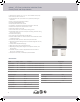


Model Details
Control Type Electronic Capacita ve Touch with OLED Screen
Indoor or Outdoor Indoor
Built-in Installa on Inset, Frameless / Overlay and Framed Cabinet Styles
Ice Size 1
1
⁄8" x 1
1
⁄8" x 1
1
⁄4"
Ice Weight (g) per unit 22 g / 0.0485 lbs
Ice Quan ty per cycle 24 Individual Cubes (1
1
⁄4 lbs)
Ice Produc on Capacity 68 lbs
Ice Storage Capacity 25 lbs
Refrigerant Type R290
Electrical Details
Electrical Requirements 115 V / 60 Hz
Volt Range 104 V ~ 127 V
Maximum Amp Fuse 15 amp
Amps Running 2.4 amps
Plumbing Water Details
Water Inlet Adapter
1
⁄4" OD Compression Fi ng*
Water Pressure Opera ng Range (psi) 20 psi – 80 psi
Integrated Water Filter System Ye s
Water Usage 16
1
⁄2 gallons per 100 lbs of ice
Factory Installed Drain Line 10 feet
Drain Required Yes (See manual for details)
*Water line not included
Approvals – Cer fi ca ons Details
Energy Star Yes
ETL Sanita on Yes
UL Commercial Yes
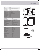
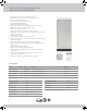
Front View
Left View
*Dimensions are the same for Panel Ready unit when
3
⁄4” panel applied
23
1
⁄4” (590 mm)*
20
11
⁄16” (526 mm)
14
7
⁄8” (377 mm)
34” to 35” (864 to 889 mm)
18
5
⁄8” (472 mm)
30” (762 mm)
34” to 35” (864 to 889 mm)
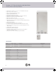
Back View
1
7
⁄8” (47 mm)
3” (75 mm)
6
23
⁄32” (171 mm)
Drain Line
Water Inlet
Water Inlet
Power Cord
Drain Line (10 )
Power Cord (6 )
3
⁄4” (19 mm)
10
7
⁄8” (276 mm)
5
7
⁄16” (138 mm)
24.00”
(610 mm)
15.00”
(381 mm)
34.00”
(867 mm)
to
35.00”
(889 mm)
6.00”
(152 mm)
11.00”
(280 mm)
Electrical hook-up
location
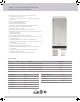
Cut-out Dimensions with Electrical
Water Line and Drain locations
Recommended location
for water line, drain and
electrical connection is
in adjacent cabinet
SAPPHIRE
CONFIDENTIAL
15” Ice Machine
9/7/20
Cut out graphics
Widths:
Ice: (including water line)
15” ADA
15” Standard
Refer
Standard
15”
24”
ADA
24”
Heights:
ADA Cutout. 32-33
Standard: 34-35
The electrical/ Inlet Water location is OK, if installing directly behind the unit or putting in adjacent cabinetry.
For non pump the height of 6.75”(172mm=89/2+127mm) For 15” ice maker is OK. It is correct to illustrate the ¼”
drop for every foot of drain line.
For drain pump models, in case of air column remaining in the pipe, the height of drain hole location should be
equal or higher than 9.8”(248mm) to ensure the drain pump running smoothly . The drain pump head is 1.5m, so
the max height of the drain pipe that the pump operates properly is 1.5m. The length of drain pipe is 10 feet(3m),
the distance of the drain pipe on left or right side should be about 9’. Please refer to the red cloud shape below for
the Details.
NOTE:
For Gravity drain models, the drain hole cannot exceed 7 inches
above the floor. For Pump models, the drain hole should be no
lower than 7 inches and no higher than 4 feet above the floor.
Recommended loca on
for water line, drain line
and electrical connec on
is in adjacent cabinet
NOTE: For Gravity drain models, the drain hole cannot exceed 7 inches above the oor.
For Pump models, the drain hole should be no lower than 7 inches and no higher than 4 feet above the oor.
24” (610 mm)
11” (280 mm)
34” (864 mm)
to
35” (889 mm)
Electrical hook-up
loca on
7” (177 mm)
15” (381 mm)
Cube Size
All speci ca ons are subject to change without no ce.
SAPPHIRE
13