UHF Wireless Microphone System UwMic9 User Manual
Statement Please read this manual carefully before using and strictly operate and store in accordance with the instructions. Please save it for your future reference. If the user manual can not help you to solve certain problems, please ask your retailer for help or email us: info@saramonic. com. Cautions 1. Do not use the unit under water, don't expose it to rain. Please store it in a cool, dry place. 2. Please use and store it in normal temperature.
CONTENTS General Introduction.................................................................. 2 Portable Receiver UwMic9-RX9................................................ 2 Introduction................................................................................... 2 Product Structure......................................................................... 2 Attaching Accessories................................................................. 4 LCD Display Operation Guide............................
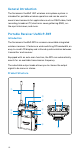
General Introduction The Saramonic UwMic9 UHF wireless microphone system is intended for portable wireless operation and can be used in several environments for applications such as DSLR video, field recording, broadcast TV, electronic news gathering (ENG), onthe-spot interviews, and more. Portable Receiver UwMic9-RX9 Introduction The Saramonic UwMic9-RX9 is a camera-mountable integrated wireless receiver.
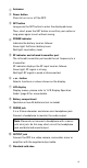
① Antennas ② Power button Press to turn on or off the RX9. ③ SET button Long press the SET button to enter the displayed menu. Then, short press the SET button to confirm your option or long press again to exit without saving. ④ POWER indicator Indicates the battery level as follows: Green light: Sufficient battery level. Red light: Low battery level. ⑤ RF indicator and infrared transmitter port The infrared transmitter port sends the set frequency to a transmitter.
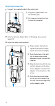
Attaching Accessories 1 Connect the supplied cable to the output jack. ① Plug the supplied cable into the OUTPUT jack. ② ① ② For a secure connection, turn to lock the connector. 2 Attach a belt clip. Please Refer to "Attaching Accessories" (page 10). 3 Attach the shoe mount adapter. ① Please attach the belt clip upside-down before attaching the shoe mount adapter. ② ① ② Push the bottom of the belt clip to make some space between the belt clip and the receiver.
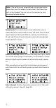
LCD Display Operation Guide ① ② ① ② ③ 1 ④ ⑤ ⑥ Home screen. If no operation is performed for 20 seconds on the other screens, the display will automatically return to the home screen. ① Group icon Indicates the power of group A is turned off. Indicates the power of group A is turned on. ② RF level indicator Indicates the current reception level. ③ Battery level indicator Displays the battery level. Please replace both batteries immediately when the indicator starts flashing.
Note: If the batteries are removed and reinserted while the power key is set to Locked, the lock state of the Power key will not be changed. You can turn on the receiver by long pressing the power button. 3 Output mode. The output mode can be selected to mono or stereo. When the output mode is mono, the audio from left and right channel will be mixed. When it is stereo, the left (Group B) and right (Group A) audio channel output will be separated. System default is mono. 4 9 Power of the Group.
6 11 Set output volume. Set the volume of output audio within the range 0 to 30. The setting is retained even after the power is turned off. Default is 30. 7 12 Auto scan function. Automatically scan an available and clear channel. Details of operation, please refer to "Using the auto scan function" (page 23). 8 13 Group ettings Matc h with TX Group ettings Matc h with TX Infrared matching function. Match the receiver and transmitter via infrared.
16 Version of the UwMic-RX9. 17 Serial Number. Body-pack Transmitter UwMic9-TX9 Introduction This transmitter is a compact transmitter that employs a crystal-controlled PLL synthesizer. It is equipped with a muting function and a locking-type microphone input connector. The RF power output can be switched among high, middle and low.
① Antenna ② AUDIO indicator / IR (infrared detector) AUDIO indicator: Indicates the audio input level. IR (infrared detector): Receives the frequency from the receiver. Solid Green: Audio input level is appropriate. Flashing Red: Audio is muted (i.e., disabled). For details on setting the mute function, please refer to "Set Mute key" (page 12). ③ POWER indicator Indicates the battery level as follows: Solid Green: Sufficient battery level. Solid Red: Low battery. ④ Audio input connector (3.
Attaching Accessories 1 Attach a belt clip. Insert one end of the belt clip into one of two holes on either side of the transmitter, and then insert the other end into the hole on the other side. 2 Connect the mcirophone. For a secure connection, turn to lock the connector. Note: Please turn off the transmitter before attaching or removing the microphone.
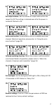
LCD Display Operation Guide ① ② ③ ④ 1 ⑤ ⑥ ⑦ Home screen. If no operatIon is performed for 20 seconds on the other screens, the display will automatically return to the home screen. ① RF transmission power indicator Indicates the current transmission power level. For details on setting the level, please see "Select RF power level" (page 12). ② Channel group indicator Indicates the channel group. ③ Mute indicator Mute OFF Mute ON ④ Battery level indicator Displays the battery level.
3 Select Channel. Long press the SET button to enter the menu. Use the "+" and "-" to select the channel you need and shot press the SET button to confirm. 4 Select Group. You can choose "A" or "B" channel group. Each group has 96 channels. Default is 'Group A." 5 Select RF power level. You can set the transmitted RF power to High, Middle or Low. Default is "High." 6 Set Mute key. If you want to mute the audio, please select "Enable" first and then short press the power button. Default is "Enable.
7 IR Match. Set to match with the receiver. The screen will display "Matching" when in process. After successful matching, it will indicate "Sync finished." 8 Set Backlight. Select ON, OFF or Delay 10 / 30 /60 seconds. Default is "Delay 10s." 9 Restore default setting. 10 Version of the UwMic9-TX9. 11 Serial Number.
Hand-held Microphone UwMic9-HU9 Introduction Saramonic HU9 is a handheld wireless UHF microphone transmitter features a compact metallic body, an easy-to-read LCD display, a RF power switch and a PLL synthesizer. The broadcast quality microphone will capture crystal clear and rich sound. It has a built-in antenna, a muting function and power lock function. The channel of HU9 is synced up with the receiver via infrared. Product Structure ① ② ④ A B C D ③ ① LCD screen A. Channel Groups.
④ Operation panel A. Infrared detector. Receives the frequency set on the receiver. B. Lock switch. Set to ON will lock the power button. It will prevent the power being turned off inadvertently during transmission. Note: The lock switch will not lock the mute function. C. RF power. Set the transmit output level to HIGH or LOW. A B ON HIGH OFF LOW LOCK RF C UHF ⑤ Battery compartment Operates on two AA batteries (not included). You could use alkaline, lithium or nickel metal hydride batteries.
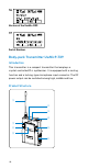
Plug-on Transmitter UwMic9-TX-XLR9 Introduction The Saramonic TX-XLR9 is a compact XLR plug-on type transmitter features a wide switching RF bandwidth, an easyto-read LCD display, +48V phantom power and mute function. It is suitable for portable wireless operation and can be used in a wide range of applications such as DSLR video, broadcast TV, ENG and more. Product Structure ① ② ③ ④ ⑤ ⑥ ⑦ ⑧ ⑨ ① XLR audio input jack Connects to an XLR microphone or audio devices with line output.
④ AUDIO indicator / IR (infrared detector) AUDIO indicator: Indicates the audio input level. IR (infrared detector): Gets the frequency from the receiver. Solid Green: Audio input level is appropriate. Flashing Red: Audio is muted (i.e., disabled). For details on setting the mute function, please refer to "Set Mute key" (page 20). ⑤ LCD screen Displays menus, please refer to "LCD Display Operation Guide" (page 19) for more details. ⑥ Power / Mute button Turns the power or mute function to on or off.
Attaching Accessories Microphone or XLR cable 1 Attach a microphone or XLR cable. Push the microphone or cable connector into the XLR audio input jack of the TX-XLR9 until it clicks into place. Microphone or XLR cable Release button 2 Disconnect a microphone or XLR cable. Press the release button and pull the microphone or XLR cable out carefully in the direction of arrow. Note: Please turn off the transmitter before attaching or removing the microphone.
LCD Display Operation Guide ① ② ③ ④ 1 ⑤ ⑥ ⑦ Home screen. If no operatIon is performed for 20 seconds on the other screens, the display will automatically return to the home screen. ① RF transmission power indicator Indicates the current transmission power level. For details on setting the level, please see "Select RF power level" (page 20). ② Channel group indicator Indicates the channel group. ③ Mute indicator Mute OFF Mute ON ④ Battery level indicator Displays the battery level.
3 Select Channel. Long press the SET button to enter the menu. Use the "+" and "-" to select the channel you need and shot press the SET button to confirm. 4 Select Group. You can choose "A" or "B" channel group. Each group has 96 channels. Default is "Group A." 5 Set the microphone drive power supply (+48V). When set to ON, 48V phantom power is supplied to the connected microphone and the "+48V" indicator lights up. Default is "+48V OFF.
Set Mute key. If you want to mute the audio, please select "Enable" first and then short press the power button. Default is "Enable." 8 IR Match. Set to match with the receiver. The screen will display "Matching" when in process. After successful matching, it will indicate "Sync finished." 9 Set Backlight. Select ON, OFF or Delay 10 / 30 /60 seconds. Default is "Delay 10s." 10 Restore default setting. 11 Version of the UwMic9-TX-XLR9. 12 Serial Number.
Operation Guide 1 Install the batteries. ① UwMic9-RX9 and UwMic9-TX9. Batteries can be inserted in the plug-on transmitter UwMic9-TX-XLR9 in the same manner. • Long press the Power key to turn the unit off. • Slide the two catches inward and pull out the battery compartment. • Insert two AA size batteries according to the polarity indicators and close the compartment. Please be sure the battery compartment is locked securely. ② UwMic9-HU9 • Long press the power button to turn the power off.
2 onnect the receiver to the mic jack of a camera, C camcorder or mixer with the supplied cable. 3 Turn on the receiver by long pressing the power button. 4 Set the channel of the receiver by two ways: ① Using the auto scan function • U se the + or – button to display the auto scan screen on the receiver. • L ong press the SET button to select “Auto scan?” • P ress the SET button to confirm. • T he channel with the least noise and interference will be displayed. A B A.
② Manually setting the receiver channel. • Use the + or – button to display the channel menu on the receiver. • Long press the SET button to select the menu. • Use the + or – button to select the desired channel and confirm it by short pressing the SET button. 5 Match the channel of receiver and transmitter. ① Using infrared transmission to transfer the frequency set on the receiver to a transmitter. For the TX9 and TX-XLR9 • Turn on the transmitter by long pressing the power button.
• Both long press the SET button to select the menu and short press it to confirm. • Place the infrared transmitter port on the receiver near the infrared detector on the transmitter. • If "Sync finished!" displayed on the LCD screen, the frequency for use on the transmitter is set. • After matching successfully, press the SET button of receiver to return to the previous menu. For HU9 • Turn the transmitter power on. • Use the + or – button to display the "Match with TX" menu on receiver.
② M anually setting the transmitter channel (Only available on the UwMic9-TX9 and the UwMic9-TX-XLR9). • Turn on the transmitter by long pressing the power button. • U se the + or – button to display the channel setting menu on the transmitter. • Long press the SET button to select the menu. • U se the + or – button to select the same channel as the receiver and confirm it by short pressing the SET button. 6 ttach the accessories you need for the receiver and A transmitter.
Spur suppression -60 dB Weight Approx. 218.7g (excluding batteries) Battery Two AA size batteries Dimensions 170.9 × 63.5 × 30.
Packing list TX9 • • • • • Body-pack transmitter: TX9 Omni-directional lavalier microphone Microphone holder clip Wind screen Belt clip TX-XLR9 • Plug-on transmitter: TX-XLR9 / 28
RX9 • • • • • Portable receiver: RX9 Shoe mount adapter Belt clip XLR to 3.5mm locking-type plug audio output cable 3.
www.saramonic.com The Saramonic logo is trademark which is registered and owned by Saramonic International. COPYRIGHT 2011-2021 SARAMONIC INTERNATIONAL ( A brand of DSQN ) Email: info@saramonic.