
Instruction Manual


A7925D 11
06/09/11
Copyright © 2009 Sargent Manufacturing Company, an ASSA ABLOY Group company. All rights reserved.
Reproductions in whole or in part without express written permission of Sargent Manufacturing Company is prohibited.
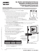
56- Electric Latch Retraction Exit Devices
Installation and Wiring Instructions
With Optional 53- Latchbolt; 55- Request to Exit;
and TL- (SARGuide) Connection Instructions
FOR INSTALLATION ASSISTANCE CONTACT SARGENT • 1-800-810-WIRE (9473) • www.sargentlock.com
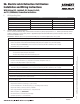
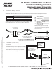
SIGNAL CAUSE TROUBLESHOOTING
Dark / Unlit Controller microprocessor is not active Confirm connections and incoming power
Steady Flashing Normal operation Cycle device by closing the timer circuit
Solid Light Input voltage is dropping out of operating range Check wire run and power supply output
2 Flashes Followed by Pause Sensor or motor issue Call 800-810-WIRE for assistance
3 Flashes Followed by Pause Mechanical issue Call 800-810-WIRE for assistance
6. LED Signalling Chart
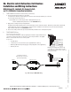
4. TIMER MODE Adjustment (Onboard Timer)
How it works: The 24 volt input is always energized and the system retracts when the timer input circuit is closed.
• When the timer circuit is closed utilizing a momentary switch, the device retracts, remains retracted for a set duration,
and releases. The duration of the retraction is set using an onboard timer setting (0 - 20 second timer adjustment).
The countdown begins when the rail is first retracted.
• When the timer circuit is closed using a maintain switch, the device retracts.
The device releases when the circuit is re-opened.
Notes:
• Note: 24V supply is constant in TIMER MODE. The duration of retraction is determined by whichever is longer:
the maintain switch closure or the onboard timer delay.
• If more than 20 seconds delay is necessary (exceeding the maximum setting), an external timer delay relay
is required (not provided).
NOTE: Refer to settings in Section III, part 5 (Fig. 19-21) for DIP Switch timer delay settings.
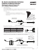
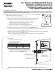
For 56- applications using the optional 53- latchbolt monitor switch (53-56-), pin 5 of the 8-pin ElectroLynx connector
will be either an NO contact or NC contact depending on the position of the DIP switches on the motor controller faceplate.
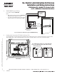
5. Configuration Instructions DIP Switch Settings (for 53- and timer duration)
Fig. 19 DIP Switch Setting
for 53- Latch Bolt Monitoring
Fig. 20 Alternate DIP
Switch Setting (53- NC)
Fig. 21 Timer Delay Settings
(Default = 5 Seconds)
0 Seconds
2 Seconds
3 Seconds
4 Seconds
5 Seconds
10 Seconds
15 Seconds
20 Seconds
Door Surface