
Instruction Manual


A7925D 3
06/09/11
Copyright © 2009 Sargent Manufacturing Company, an ASSA ABLOY Group company. All rights reserved.
Reproductions in whole or in part without express written permission of Sargent Manufacturing Company is prohibited.
56- Electric Latch Retraction Exit Devices
Installation and Wiring Instructions
With Optional 53- Latchbolt; 55- Request to Exit;
and TL- (SARGuide) Connection Instructions
FOR INSTALLATION ASSISTANCE CONTACT SARGENT • 1-800-810-WIRE (9473) • www.sargentlock.com
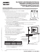
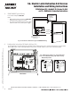
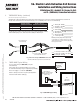
IMPORTANT: ElectroLynx connectors plug and
lock together in only one way.
Do NOT force connectors together.
Fig. 4 ElectroLynx Connections
Locking Mechanism
Receptacle
Plug
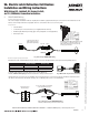
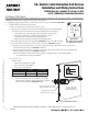
9. ElectroLynx Wiring System
8-pin M
8-pin F
8-pin M
8-pin F
8-pin F
McKinney QC12 Hinge
(available direct from McKinney)
4-pin F
8-pin M4-pin M
4-pin F
4-pin M
Typical ElectroLynx Wiring Harness Connections
Provided With Product
TL-53-55-56- wired in TIMER MODE requires all 12 wires.
Fig. 5 Typical ElectroLynx Wiring
*3” Harness
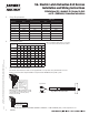
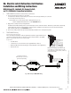
8. DIP (Dual Inline Package) Switch Settings
DIP Switch assignments are as follows, starting from left:
1: Closed (Switch set to ON) when selecting 53- NC
(Normally Closed) contact.
2: Closed (Switch set to ON) when selecting 53- NO
(Normally Open) contact.
NOTE: Only 1 or 2 should be closed at one time,
not both.
3: Closed when bypassing external trigger, i. e., Power Mode.
4, 5, 6: Select software options, allows up to 8 Time/Delay
settings (refer to TIMER MODE, Section III, part 5).
Note: *The three inch connector is not included with the product, door, or hinge and
must be ordered separately (P/N available in POWER MODE Wiring section).
Fig. 3 DIP Switch Settings
(Factory Default Shown)
Door
Surface
Default Setting: 53- NO (Normally Open) and POWER MODE set to ON.