
Instruction Manual


Copyright © 2011 Sargent Manufacturing Company, an ASSA ABLOY Group company. All rights reserved.
Reproductions in whole or in part without express written permission of Sargent Manufacturing Company is prohibited.
06/09/11
4 A7925D
56- Electric Latch Retraction Exit Devices
Installation and Wiring Instructions
With Optional 53- Latchbolt; 55- Request to Exit;
and TL- (SARGuide) Connection Instructions
FOR INSTALLATION ASSISTANCE CONTACT SARGENT • 1-800-810-WIRE (9473) • www.sargentlock.com
1. POWER MODE Installation Instructions
How it works: Rail retracts when power is applied and releases when power is removed.
1. Mount 80- Series exit device using mechanical installation instruction sheet(s) provided.
Note: Ensure proper mechanical function before attempting electrical retraction:
• Verify the push rail can be fully depressed and the latch is fully retracted.
• On vertical rod exit devices, verify the latchbolts do not enter hold-back
position until the push rail is fully depressed.
• Adjust device mechanically, as required, before applying power.
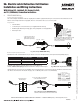
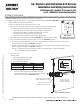
2. Connect the ElectroLynx harness in the door (Fig. 8
ElectroLynx POWER MODE Wiring):
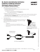
a. Plug the 8-pin ElectroLynx connector from the rail into the 3" ElectroLynx harness or splice into non-ElectroLynx harness
(Fig. 10 Non-ElectroLynx POWER MODE Wiring).
b. Feed the 3" harness through the 1” hole in the door and secure the rail to the door using the mounting bracket
and two supplied screws (Fig. 7 POWER MODE Installation Diagram).
Note: Do not install the end cap until electrical operation is verified in order to confirm LED signalling.
Do not discard the end cap and hardware.
3. Ensure DIP switch (position 3) enables POWER MODE (Fig. 6).
4. Connect the ElectroLynx harness to the hinge and secure the electric
hinge to door.
Notes: Make sure no wires are pinched or damaged in the process.
Refer to detailed wiring instructions under POWER MODE wiring.
4. Apply 24V according to 56- input requirements (below):
Confirm that the LED is blinking, that the system fully unlocks, and that
all bolts clear the strikes. Troubleshoot the device if issues are observed
using the steps outlined at the end of the POWER MODE section.
5. Store excess wiring under end cap and assemble
with provided screws. Avoid pinching wires.
SECTION II: POWER MODE
In this configuration, the device is not energized when locked. When energized with a 24 volt input, the push rail and latch(es)
will retract and remain in the retracted position until power is removed. Power is typically applied through a relay triggered by
an access control device.
For installations using the onboard timer circuit, refer to SECTION III: TIMER MODE.
56- Input Requirements
Voltage: 24VDC
• Filtered and regulated power supply
• Motor operating current: 600mA
• Motor hold current: 250mA
Note: Earth Ground is required for Electrostatic Discharge (ESD)
protection unless the metal door and frame are already earth
grounded; otherwise, earth ground wiring is required at pin 4
(Fig. 8 ElectroLynx POWER MODE Wiring).
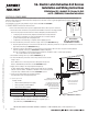
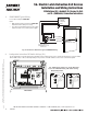
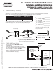
Mounting Bracket
Screw Location
1” Diameter
Hole in Door
Exit Device
A 3" ElectroLynx harness
is required to connect the
rail to the ElectroLynx hinge.
Note: Specified and
ordered separately
McKinney QC8 Electric
Hinge (with 8-pin connector)
Fig. 7 POWER MODE Installation
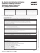
55-56- or 12-55-56-
80 Series Rail with
8-pin Connector
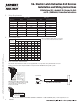
55- REX 53- LATCH BOLT
Contact Rating (Resistive) 300mA @ 30VDC 2A @ 30VDC
Contact Resistance 150m Ω 30m Ω
Fig. 6 DIP Switch Setting
for POWER MODE Installation
Door Surface