
Instruction Manual


A7925D 5
06/09/11
Copyright © 2009 Sargent Manufacturing Company, an ASSA ABLOY Group company. All rights reserved.
Reproductions in whole or in part without express written permission of Sargent Manufacturing Company is prohibited.
56- Electric Latch Retraction Exit Devices
Installation and Wiring Instructions
With Optional 53- Latchbolt; 55- Request to Exit;
and TL- (SARGuide) Connection Instructions
FOR INSTALLATION ASSISTANCE CONTACT SARGENT • 1-800-810-WIRE (9473) • www.sargentlock.com
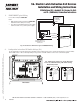
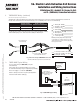
Non-ElectroLynx Opening Installation
Standard door with standard electric hinge: Molex connectors with flying leads can be purchased separately (Fig. 9).
2. POWER MODE Wiring
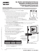
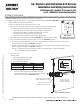
ElectroLynx Opening Installation
This is the simplest installation method, requiring the installer to plug the ElectroLynx connectors from the exit device to the
harness to the hinge and then to the pigtail, which is connected to the access control system.
Requirements
• 56- Exit device
• 3” ElectroLynx connector harness (not supplied with 56- device)
• McKinney QC ElectroLynx hinge (type of hinge depends on the application)
• ElectroLynx door
Fig. 8 ElectroLynx POWER MODE Wiring
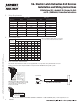
3” ElectroLynx Harness
With 8-pin Connector
(purchased separately)
8-pin F
8-pin M
8-pin M
MOLEX BOTH ENDS MOLEX TO PINS
3 INCH QC-C003 QC-C003P
6 INCH QC-C006 QC-C006P
12 INCH QC-C012 QC-C012P
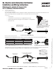
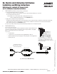
Fig. 10 Non-ElectroLynx POWER MODE Wiring
56- Wires with ElectroLynx Connector Removed
Loose wires with no termination
connected with wire nuts
Non-ElectroLynx
Electric Hinge
To identify part numbers and order harness(es), visit the McKinney
website, www.mckinneyhinge.com, and search the catalog for ElectroLynx.
If Molex pinned connectors are not available, remove the ElectroLynx connector from the 56- Exit Device and wire nut the
56- wires to the wires from the electric hinge (color coordinating wire colors is recommended).
Fig. 9 Molex with 12-pin Connector Pinned
1 - Black (56- 0VDC)
2 - Red (56- +24VDC)
3 - White (53- C)
4 - Green (EG)
5 - Orange (53- NC/NO)*
6 - Blue (55- C)
7 - Brown (55- NO)
8 - Yellow (55- NC)
1 - Black (56- 0VDC)
2 - Red (56- +24VDC)
3 - White (53- C)
4 - Green (EG)
5 - Orange (53- NC/NO)*
6 - Blue (55- C)
7 - Brown (55- NO)
8 - Yellow (55- NC)
*NO/NC (Normally Open/Normally Closed)
is selectable on controller (refer to 53-
DIP Switch Instructions in Section III).
Factory preset is NO.
4-pin F
Not Used
4-pin F
Not Used