
Instruction Manual


Copyright © 2011 Sargent Manufacturing Company, an ASSA ABLOY Group company. All rights reserved.
Reproductions in whole or in part without express written permission of Sargent Manufacturing Company is prohibited.
06/09/11
6 A7925D
56- Electric Latch Retraction Exit Devices
Installation and Wiring Instructions
With Optional 53- Latchbolt; 55- Request to Exit;
and TL- (SARGuide) Connection Instructions
FOR INSTALLATION ASSISTANCE CONTACT SARGENT • 1-800-810-WIRE (9473) • www.sargentlock.com
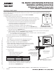
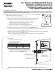
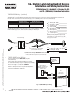
3. POWER MODE Typical Wiring
For use when wiring in POWER MODE.
Notes:
• Onboard timer will not function in POWER MODE.
Add external time delay if necessary.
• The switch is wired between the power supply
and the load. Do not cycle the power supply.
24VDC
Power Supply
QC8 Electric Hinge
0V (Black)
+24V (Red)
EGND
Green (EGND)
Red (+24V)
Black (0V)
Maintain
or Relay Switch, i.e.,
Card Reader, Access
Control, etc.
( + )
( - )
( NO )
( NC )
Fig. 11 56- 80 Series Exit Device Typical POWER MODE Wiring
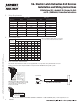
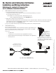
For 56- applications using the optional 53- latchbolt monitor switch (53-56-), pin 5 of the 8-pin ElectroLynx connector will be
either a NO contact or NC contact depending on the position of the DIP switches on the motor controller faceplate.
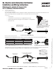
4. Configuration Instructions DIP Switch Settings (53-)
Fig. 12 DIP Switch Setting
for 53- Latch Bolt Monitoring
NO (Default) Shown
Fig. 13 NC Alternative
DIP Switch Setting
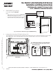
Door Surface