Data Transfer Device (DTD) Specifications/Requirements: Mechanical: 3 7/8” W x 5 3/4” L x 1 1/2” D PC Connection: USB Port (v1.1 or v2.0) Only Environmental: Environment: Store Indoors. Do not get wet. Temperature Tolerance: 32º F to 120º F (0º – 49ºC) Software Compatibility: SoloPlusTM v1.0 (or higher) DTD Printer Utility (available with SoloPlusTM v1.0 or higher) Electrical: Operating Voltage: 6V (Four AA Batteries) Firmware Version: This manual applies to firmware version 00.
Table of Contents Data Transfer Device Operating Instructions Table of Contents Section 1: Basic Operation.............................................................................................3 1.1 DTD Diagram.................................................................................................................................3 1.2 DTD Battery Installation................................................................................................................3 1.3 DTD Power........
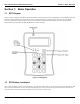
Data Transfer Device Operating Instructions Section 1: Basic Operation Section 1: Basic Operation 1.1 DTD Diagram Figure 1 below is a diagram of the DTD. The diagram illustrates the location of the Power On/Off buttons, the backlighting button and the LEDs. These are explained in detail in later sections. The Infrared (IR) Port is located at the top of the unit above the display where it says “Data Port.” Refer to figure 2 on page 5 for a detailed view.
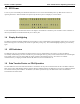
Section 1: Basic Operation 1.3 Data Transfer Device Operating Instructions DTD Power To turn on power to the DTD press and hold the ON button. for two seconds until the DTD powers up. Note: See the section 1.2 regarding the batteries. When the DTD is first powered-up the Start-up Screen is displayed, as shown below. To turn off the DTD press the OFF button shown in the diagram. The DTD has an automatic power-off feature.
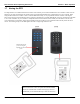
Data Transfer Device Operating Instructions 1.7 Section 1: Basic Operation Aiming the DTD The diagram below is included to illustrate the location of the infrared port on both the DTD and the door controllers. Please note the diagram is not meant to demonstrate the actual position you should hold the DTD when communicating to a door controller. When using the DTD with devices similar to Unit # 1 hold the DTD horizontally, so it's perpendicular with the controller.
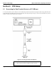
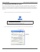
Section 2: DTD Setup Data Transfer Device Operating Instructions Section 2: DTD Setup 2.1 Connecting the Data Transfer Device to a PC USB port To connect the DTD to your PC USB port, use the USB cable provided with your DTD. First plug the small end (Type Mini-B) of the 6-foot USB cable into USB connector on the top of the DTD. Then plug the large end (Type A) of the 6-foot USB cable into your PC's USB port. Figure 2 below illustrates this connection.
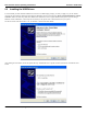
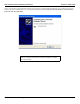
Data Transfer Device Operating Instructions 2.2 Section 2: DTD Setup Installing the USB Drivers To use the DTD you must install the USB drivers on the PC. The DTD is plug and play, so when you plug it in, your PC should recognize the new hardware and launch the Found New Hardware Wizard as shown below. Please note that this hardware wizard runs twice. Follow the same steps both times. Note: These instructions are for a typical Windows XP system.
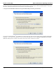
Section 2: DTD Setup Data Transfer Device Operating Instructions On the next screen select “Search for the best driver in these locations.” at the top. If you've already installed SoloPlusTM onto the PC, then select “Include this location in the search” and browse to the following path: C:\Program Files\ASSAABLOY\SoloPlus1\Program\Utilities\USB_Driver\FTDI_XP-2K-20030 If you haven't installed SoloPlusTM, the USB drivers are also located on the CD.
Data Transfer Device Operating Instructions Section 2: DTD Setup Next a screen appears indicating the files are being copied, then you're presented with the following screen to indicate the process is finished. Click on the Finish button to close the Found New Hardware Wizard. Please note that this hardware wizard runs twice. Follow the same steps both times.
Section 2: DTD Setup 2.3 Data Transfer Device Operating Instructions Determining the USB COM port number When you connect the Data Transfer Device to your computer's USB port, the PC automatically assigns it a COM port number. You must then select this COM port in the software to communicate to your DTD. You can either use the automatic search feature in SoloPlusTM or follow the instructions below to determine the COM port number. Note: These instructions are for a typical Windows XP system.
Data Transfer Device Operating Instructions 3. Section 2: DTD Setup When the device manager list opens, expand Ports (COM & LPT) by clicking the + symbol. Under this is a list of the COM ports on your PC. Look for USB Serial Port (COMx) in the list. The COM port is shown to the right. The example below shows the DTD is assigned to COM4. Note: If you are unsure of which device it is, unplug the USB cable and the screen will refresh. Take note of which devices are in the list.
Section 3: DTD Mode Data Transfer Device Operating Instructions Section 3: DTD Mode From the factory, the DTD is set in DTD Mode. This mode is used to send data and retrieve transaction event logs from controllers that support two way communications. Note: If you need to change the mode to Printer Mode, please refer to section 3.3 and 3.3.3. When the DTD is first powered-up the the Start-up Screen is displayed (refer section 1.3).
Data Transfer Device Operating Instructions 3.1 Section 3: DTD Mode IMPORT/EXPORT Menu The IMPORT/EXPORT menu is used to export data to the door controller and import transactions from it. There are two options: AUTO SEARCH and MANUAL SEARCH. These options are described below. Note: The bottom line of this screen indicates which import/export option is set. Refer to section 3.2.4. 3.1.1 Exporting using the AUTO SEARCH Menu The AUTO SEARCH option is used to communicate to a door automatically.
Section 3: DTD Mode Data Transfer Device Operating Instructions When the transfer begins the following screen appears and the green LED turns on. If at any point you lose communications with the door controller, the red LED turns on. You have 10 seconds to move the DTD back into range. When the data transfer is complete the following message appears. Press the left arrow to exit to the menu. If a matching door file is not found, the following message appears.
Data Transfer Device Operating Instructions Section 3: DTD Mode The doors are displayed as shown below. The site name is on the first line and the door name is on the second line. When you reach the door you are looking for, stop. Now enter your Comm Unlock code on your door controller and aim your DTD at the Infrared (IR) port on the door controller and press the ENTER key.
Section 3: DTD Mode Data Transfer Device Operating Instructions When data transfer is complete, the message below appears. Press the up or down arrows to move through the door list. 3.2 UTILITIES Menu To access the UTILITIES Menu press the ENTER button from the Start-up Screen. Next you are presented with three choices. Press the down arrow to move the cursor to the UTILITIES option and press the ENTER key. You have four choices in this menu, as shown below. 3.2.
Data Transfer Device Operating Instructions 3.2.3 Section 3: DTD Mode SET DOOR CLOCK SoloPlusTM has an option to automatically set the time and date in the controller when you export. You also have the option to manually set the time and date in the door controller using this menu option. First, enter your Comm Unlock code on the door controller. Next aim your DTD at the Infrared (IR) port on the controller and press the ENTER key. If successful, the message below is displayed on the DTD screen. 3.2.
Section 3: DTD Mode 3.3 Data Transfer Device Operating Instructions STATUS Menu The STATUS menu has three options. The first displays information about the doors stored on the DTD, the second has information regarding the DTD unit and third option allows you to select the DTD operating mode. 3.3.1 DOOR LIST OPTIONS The DOOR LIST OPTIONS menu is used to view the status of the doors currently on the DTD. The first option, SHOW ALL DOORS, displays a complete list of export files on the DTD.
Data Transfer Device Operating Instructions 3.4 Section 3: DTD Mode Security Risk Warning (W01) When the DTD attempts to communicate to the door controller during the import/export process, it first asks the controller if program mode was entered. If program mode was entered manually on the controller, the following warning is displayed. This warning means that someone may have programmed data into the controller that doesn't match the PC software database.
Section 4: Printer Mode Data Transfer Device Operating Instructions Section 4: Printer Mode 4.1 SET PRINTER MODE To configure your DTD to operate in Printer Mode (from DTD Mode), go to the STATUS MENU as described in section 3.3, then select the SET MODE option as discussed in section 3.3.3. When the screen below appears, move the cursor down to the SET PRINTER MODE option and press ENTER. The = symbol will move down to the new setting, as shown. To return to the Start-Up Screen press the * key. 4.
Data Transfer Device Operating Instructions 4.2.1 Section 4: Printer Mode INFRARED CAPTURE Note: It's important to note, prior to using the INFRARED CAPTURE function in Printer Mode, how this feature differs from the Import/Export function in DTD Mode. In Printer Mode, the DTD can only receive data, because the door controllers only support one-way communication.
Section 4: Printer Mode 4.2.2 Data Transfer Device Operating Instructions SEARCH DOORS The SEARCH DOORS options lets you search through the files you have captured and allows you to view the data. When you hit ENTER on SEARCH DOORS the following screen appears. Use the up and down arrows on the DTD to browse through the files. Each session is stored as a separate file and uses a time/date stamp to name the file. When you reach the file you're looking for press the ENTER key to view it.
Data Transfer Device Operating Instructions 4.2.3 Section 4: Printer Mode Status Menu The status menu in Printer Mode contains the ABOUT option and SET MODE options. The ABOUT option contains information about the DTD, such as firmware part number and memory size. The SET MODE option allows you to change the DTD operating mode, as discussed in section 4.1. 4.
Section 4: Printer Mode 4.3.4 Data Transfer Device Operating Instructions Viewing and Printing Infrared Log Files The files are available for viewing directly in the DTD Printer Utility. Select the file you want to view in the left hand column and the data is displayed in the right hand column. The files are also stored as text files on the PC in the following folder: C:\Program Files\DTD Printer Utility\LogFiles.
Data Transfer Device Operating Instructions Section 5: Updating the DTD Firmware Section 5: Updating the DTD Firmware The DTD contains a feature that allows you to update the DTD firmware in the field. As new features and enhancements are available, the new firmware is downloaded to your PC when you run iUpdate through SoloPlusTM. Please refer to the SoloPlusTM documentation for complete details on updating the firmware.
Section 7: Copyright Information Data Transfer Device Operating Instructions Section 7: Copyright Information Copyright © 2009 ASSA ABLOY Inc. All Rights Reserved. SoloPlus™ is a trademark of ASSA ABLOY Inc. Other company or product's brand names may be trademarks or registered trademarks of their respective owners and are mentioned for reference purposes only. Page 26 of 26 Corbin Russwin # FM 296; Sargent # A7973B Rev. 1.