Installation Instructions For Profile Series v.G1.5 Exit Device A7856B Copyright © 2009, Sargent Manufacturing Company, an ASSA ABLOY Group company. All rights reserved. Reproduction in whole or in part without the express written permission of Sargent Manufacturing Company is prohibited. FOR ASSISTANCE, CONTACT SARGENT AT 800-727-5477 or www.sargentlock.
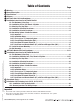
Table of Contents 1 2 3 4 5 6 05/04/09 A7856:B Copyright © 2009, Sargent Manufacturing Company, an ASSA ABLOY Group company. All rights reserved. Reproduction in whole or in part without the express written permission of SARGENT Manufacturing is prohibited. 7 8 9 10 Page Warning.........................................................................................................................................................1 General Description.....................................................
Profile Series v.G1.5 Exit Device 1 Warning Warning: Changes or modifications to this unit not expressly approved by the party responsible for compliance could void the user's authority to operate the equipment. This device complies with Part 15 of the FCC Rules. Operation is subject to the following two conditions: (1) This device may not cause harmful interference, and (2) this device must accept any interference received, including interference that may cause undesired operation.
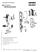
Profile Series v.G1.5 Exit Device 5 Parts Breakdown 8877/8878 x ET x Lever Design Profile Series Rim Exit Device 9 3 5 6 15 7 4 1 2 13 13 (X2) 18 (X4) 17 05/04/09 A7856:B Copyright © 2009, Sargent Manufacturing Company, an ASSA ABLOY Group company. All rights reserved. Reproduction in whole or in part without the express written permission of SARGENT Manufacturing is prohibited.
Profile Series v.G1.
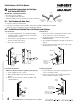
Profile Series v.G1.5 Exit Device 6 Installation Instructions for Rim Type Exit Device 8877/8878 Inside IMPORTANT: BEFORE STARTING • This device is non handed • Door should be fitted and hung • Verify box label for size of exit device, function and hand 6.1 – Exit Hardware & Door Prep Left Hand Reverse Bevel "LHRB" Right Hand Reverse Bevel "RHRB" Outside 1. If using a mullion, install in frame. 2.
Profile Series v.G1.5 Exit Device Rim Installation Instructions (Continued) 6.3 – Attaching Fire Stop Plate NOTE: Required for 12- Fire Rated doors only. 1. Drill (2) 1/8" diameter holes if the door is not supplied with them. 2. Secure fire stop plate to door with (2) #8 x 1/2" self tapping screws. Non Fire Rated Exterior DoorsInstall Weather Conduit (P/N 52-2847) as shown below CL of 1-1/2" Dia. (2) 1/8" Dia. Holes can be 1-1/2'' Dia.
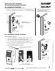
Profile Series v.G1.5 Exit Device Rim Installation Instructions (Continued) 6.5 – Installation of Inside Escutcheon 1. Connect ground wire to terminal E3 (Fig. 1), keypad harness to controller (Fig. 2), and ET motor harness to motor connector (Fig. 3). 2. Place extra wire inside door hole and/or outside escutcheon being careful not to pinch wires. 3. Connectors go on only one way, do not offset connector and be sure they are completely seated.
Profile Series v.G1.5 Exit Device Rim Installation Instructions (Continued) 6.6 – Hardwiring Options & Inside Escutcheon NOTE: If hardwiring IS NOT REQUIRED, then go to Step #6.7 Hardwiring options include one or a combination of the following; Forced/Propped Door, Hard Power and/or Remote Unlock (REX) 6.6.A. – Important 1. Caution: Disconnect all input power before beginning installation to prevent electrical shock and equipment damage. 2. Installer must be a trained, experienced service person. 3.
Profile Series v.G1.5 Exit Device Rim Installation Instructions (Continued) 05/04/09 A7856:B Copyright © 2009, Sargent Manufacturing Company, an ASSA ABLOY Group company. All rights reserved. Reproduction in whole or in part without the express written permission of SARGENT Manufacturing is prohibited. 6.6.D – Forced/Propped Door Option (DM-) Installation 1. ElectroLynx™ System Wiring Instructions (refer to Fig. 1 and Fig. 2) a. Look for the mating part on ASSA ABLOY doors & frames.
Profile Series v.G1.5 Exit Device Rim Installation Instructions (Continued) A7856B • 800-810-WIRE (9473) • www.sargentlock.com 9 05/04/09 A7856:B Installation 1. ElectroLynx™ System Wiring Instructions (refer to Fig. 1 and Fig.3) a. Look for the mating part on ASSA ABLOY doors & frames. Then plug in all connectors as shown in Fig. 3 during product installation b. Hard wire hard power and/or remote unlock (REX), as shown 2. Non-ElectroLynx™ System Wiring Instructions (refer to Fig. 1 and Fig.3) a.
Profile Series v.G1.5 Exit Device Rim Installation Instructions (Continued) 05/04/09 A7856:B Copyright © 2009, Sargent Manufacturing Company, an ASSA ABLOY Group company. All rights reserved. Reproduction in whole or in part without the express written permission of SARGENT Manufacturing is prohibited. 6.6.F – Hard Power and Remote Unlock (91-) with Forced/Propped Door (DM-) Installation 1. ElectroLynx™ System Wiring Instructions (refer to Fig. 1 and Fig. 4) a.
Profile Series v.G1.5 Exit Device Rim Installation Instructions (Continued) Battery keeper 6.7 – Inside Escutcheon Mounting Battery keeper Note: For RF Technology versions (G1-TU, G1-TP, G1-TA) refer to Section 9 when installing/removing battery keeper. 1. Insert #8-32 x 1-1/4" screws through inside escutcheon and thread into outside escutcheon Battery cover (Fig. 1). Straighten escutcheons and tighten securely.
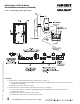
Profile Series v.G1.5 Exit Device 7 Parts Breakdown 8977/8978 x ET x Lever Design Profile Series Mortise Exit Device 9 3 5 Door 6 15 7 4 2 1 19 (X4) 13 05/04/09 A7856:B Copyright © 2009, Sargent Manufacturing Company, an ASSA ABLOY Group company. All rights reserved. Reproduction in whole or in part without the express written permission of SARGENT Manufacturing is prohibited.
Profile Series v.G1.5 Exit Device 2 2 2 PART No.
Profile Series v.G1.5 Exit Device 8 Installation Instructions for 8977-8978 Mortise Exit Inside IMPORTANT: BEFORE STARTING • Check hand of door - this device is not reversible • Door should be fitted and hung • Verify box label for size of exit device, function and hand Left Hand Reverse Bevel "LHRB" Outside Right Hand Reverse Bevel "RHRB" 8.
Mortise Installation Instructions (Continued) 8.2 – Installation of Mortise Lock, Trim, Chassis & Cylinder (Continued) B. Exit Chassis: 1. Route “ET” harness along track cutout for wood doors and access hole for metal doors 2. Mount exit chassis carefully. Do not pinch harness wires 3. Position exit chassis on door with lever arm under rear section of mortise lock 4. Using (2) 1/4-20 x 2-3/8" flat head screws, attach chassis to “ET” control 5.
Profile Series v.G1.5 Exit Device Mortise Installation Instructions (Continued) 8.3 – Attaching Fire Stop Plate NOTE: Required for 12- Fire Rated doors only. 1. Drill (2) 1/8" diameter holes if the door is not supplied with them. 2. Secure fire stop plate to door with (2) #8 x 1/2" self tapping screws. Non Fire Rated Exterior DoorsInstall Weather Conduit (P/N 52-2847) as shown below CL OF 1-1/2" Dia. 1-1/2" Dia. (2) 1/8" Dia.
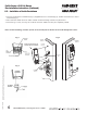
Profile Series v.G1.5 Exit Device Mortise Installation Instructions (Continued) 8.5 – Installation of Inside Escutcheon 1. Connect ground wire to terminal E3 (Fig. 1), keypad harness to controller (Fig. 2), and ET motor harness to motor connector (Fig. 3). 2. Place extra wire inside door hole and/or outside escutcheon being careful not to pinch wires. 3. Connectors go on only one way. Do not offset connector and be sure they are completely seated.
Profile Series v.G1.5 Exit Device Mortise Installation Instructions (Continued) 8.6 – Hardwiring Options & Inside Escutcheon NOTE: If hardwiring IS NOT REQUIRED, then go to Step #6.7 (page 11) Hardwiring options include one or a combination of the following: Forced/Propped Door, Hard Power and/or Remote Unlock (REX) 8.6.A. – Important 1. Caution: Disconnect all input power before beginning installation to prevent electrical shock and equipment damage. 2.
Profile Series v.G1.5 Exit Device 8.6.D – Forced/Propped Door Option (DM) A7856B • 800-810-WIRE (9473) • www.sargentlock.com 19 05/04/09 A7856:B Installation 1. ElectroLynx™ System Wiring Instructions (refer to Fig. 1 and Fig. 2) a. Look for the mating part on ASSA ABLOY doors & frames. Then plug in all connectors as shown in Fig. 2 during product installation b. Hard wire door status switch as shown 2. Non-ElectroLynx™ System Wiring Instructions (refer to Fig. 1 and Fig. 2) a.
Profile Series v.G1.5 Exit Device Mortise Installation Instructions (Continued) 05/04/09 A7856:B Copyright © 2009, Sargent Manufacturing Company, an ASSA ABLOY Group company. All rights reserved. Reproduction in whole or in part without the express written permission of SARGENT Manufacturing is prohibited. 8.6.E – Hard Power & Remote Unlock (91-) Installation 1. ElectroLynx™ System Wiring Instructions (refer to Fig. 1 and Fig. 3) a. Look for the mating part on ASSA ABLOY doors & frames.
Profile Series v.G1.5 Exit Device Mortise Installation Instructions (Continued) A7856B • 800-810-WIRE (9473) • www.sargentlock.com 21 05/04/09 A7856:B Installation 1. ElectroLynx™ System Wiring Instructions (refer to Fig. 1 and Fig. 4) a. Look for the mating part on ASSA ABLOY doors & frames. Then plug in all connectors as shown in Fig. 4 during product installation b. Hard wire forced/propped, hard power and/or remote unlock (REX), as shown 2. Non-ElectroLynx™ System Wiring Instructions (refer to Fig.
Profile Series v.G1.5 Exit Device 9 Operational Check 1. Refer to Steps 6.7 & 6.8 to complete installation 2. For devices with cylinders, insert key into cylinder and rotate 3. The key will retract the latch, the key should rotate freely 4. Depress inside rail to retract latch 5. Enter 1234* to unlock outside lever handle and retract latch 6.
SARGENT Manufacturing Company 100 Sargent Drive New Haven, CT 06511 USA 800-727-5477 • www.sargentlock.com Founded in the early 1800s, SARGENT® is a market leader in locksets, cylinders, door closers, exit devices, electro-mechanical products and access control systems for new construction, renovation, and replacement applications. The company’s customer base includes commercial construction, institutional, and industrial markets. Copyright © 2009 Sargent Manufacturing Company, an ASSA ABLOY Group company.