
Owner's manual


15
A7856B • 800-810-WIRE (9473) • www.sargentlock.com
Profile Series v.G1.5 Exit Device
05/04/09 A7856:B Copyright © 2009, Sargent Manufacturing Company, an ASSA ABLOY Group company. All rights reserved.
Reproduction in whole or in part without the express written permission of SARGENT Manufacturing is prohibited.
Mortise Installation Instructions (Continued)
8.2 – Installation of Mortise Lock, Trim, Chassis & Cylinder (Continued)
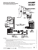
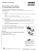
Inside of door
Exit Chassis
(2) 1/4 - 20 x 2 3/8''
Flat head
machine screws
Wire
h
arness
Outside of
door
Inside of
door
Cylinder
set screw
Cylinder
Correct Incorrect
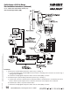
Chassis
Lever
Latchbolt
Lever arm
(4) #10 Wood
screws
or #10-24
machine
screws
Outside of
door
Inside of
door
Cylinder
set screw
Cylinder
C
orrect Incorrect
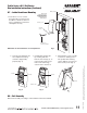
Chassis
Lever
Latchbolt
Lever arm
(4) #10 Wood
screws
or #10-24
machine
s
crews
Outside of
door
Inside of
door
Cylinder
set screw
C
ylinder
C
orrect Incorrect
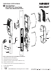
C
hassis
Lever
Latchbolt
Lever arm
(4) #10 Wood
screws
o
r #10-24
m
achine
s
crews
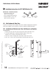
B. Exit Chassis:
1. Route “ET” harness along track cutout for wood doors and access hole for metal doors
2. Mount exit chassis carefully. Do not pinch harness wires
3. Position exit chassis on door with lever arm under rear section of mortise lock
4. Using (2) 1/4-20 x 2-3/8" flat head screws, attach chassis to “ET” control
5. Fasten exit chassis to door using (4) #10 wood screws or #10-24 machine screws
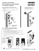
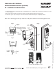
C. Cylinder Installation
NOTE: For devices without cylinders, skip this section.
1. Back cylinder set screw out of mortise lock
2. Insert cylinder through “ET” control and thread into
mortise lock until cylinder is flush with “ET”
3. Tighten cylinder set screw
Outside of door