
Owner's manual


16
800-810-WIRE (9473) • www.sargentlock.com • A7856B
Profile Series v.G1.5 Exit Device
05/04/09 A7856:B Copyright © 2009, Sargent Manufacturing Company, an ASSA ABLOY Group company. All rights reserved.
Reproduction in whole or in part without the express written permission of SARGENT Manufacturing is prohibited.
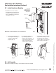
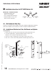
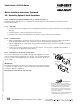
8.3 – Attaching Fire Stop Plate
C
L
OF 1-1/2" Dia.
(2) Self tapping
s
crews #8 x 1/2"
long for wood &
metal doors
(2) 1/8" Dia.
holes required
Slot
1-1/2" Dia.
7/8"
1
-1/2"
Fire stop
plate
NOTE: Fire stop plate
is required on all fire
rated doors only
NOTE: Required for 12- Fire Rated doors only.
1. Drill (2) 1/8" diameter holes if the door is not supplied
w
ith them.
2. Secure fire stop plate to door with (2) #8 x 1/2" self
tapping screws.
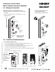
Mortise Installation Instructions (Continued)
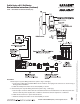
A. Insert Wires and Connector
1. For exterior applications, gasket (68-1400) should be used to seal
between escutcheon and outside door surface.
2. For 12- fire rated devices, feed keypad ribbon cable/connector from
outside of door through gasket then fire stop plate.
3. For non-12- exit devices, feed connector and wires through gasket then
hole in door.
4. Place escutcheon against door surface.
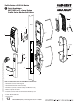
Wires & Connector
go through fire
stop plate
Ground wire
Keypad ribbon
cable/connector
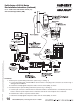
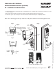
8.4 – Installation of Outside Escutcheon
For exterior
applications
gasket (68-1400)
should be
placed between
the escutcheon
and the
door surface
-
+
-
+
-
+
-
+
+
-
+
-
Security
screw
Security tool
01-0297 included
Battery keeper
Battery cover
- Polarity
+ Polarity
Bottom slots
Top tab
Tabs
Top slots
Non Fire Rated Exterior Doors-
Install Weather Conduit
(P/N 52-2847) as shown below
Ribbon Cable Orientation:
Install with cable exiting DOWN, as shown.