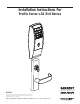
Installation Instructions For Profile Series v.G1 Exit Device A7757B Copyright © 2004, 2008, Sargent Manufacturing Company, an ASSA ABLOY Group company. All rights reserved. Reproduction in whole or in part without the express written permission of Sargent Manufacturing Company is prohibited. FOR ASSISTANCE, CONTACT SARGENT AT 800-727-5477 or www.sargentlock.
Profile Series v.G1 Exit Device Table of Contents Page 1 Warning 2 General Description ...........................................................................1 3 Specifications ....................................................................................1 4 Features .............................................................................................1 5 Parts Breakdown .............................................................................
Profile Series v.G1 Exit Device 2 General Description The SARGENT Profile Series v. G1 Rim/Mortise Exit Device is designed for areas which require stand alone authorized entry. It is a self-contained microprocessorcontrolled keypad with non-volatile memory. The keypad will hold a total of 100 (LK)/2000 (GI-LU, GI-PK, GI-PA, G1-TU, G1-TP, G1-TA) different user codes. User locations “01” & “02” are utilized for Master and Supervisory Codes, respectively.
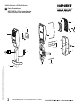
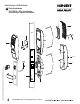
Copyright © 2006, 2008, Sargent Manufacturing Company, an ASSA ABLOY Group company. All rights reserved. Reproduction in whole or in part without the express written permission of Sargent Manufacturing Company is prohibited. Profile Series v.G1 Exit Device 5 Parts Breakdown 8877/8878 x ET x Lever Design Profile Series Rim Exit Device 9 3 5 6 15 7 1 2 11 2 4 13 13 (X2) 12 14 13 (X2) 800-810-WIRE (9473) • www.sargentlock.
Profile Series v.G1 Exit Device PART No.
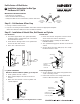
Copyright © 2006, 2008, Sargent Manufacturing Company, an ASSA ABLOY Group company. All rights reserved. Reproduction in whole or in part without the express written permission of Sargent Manufacturing Company is prohibited. Profile Series v.G1 Exit Device 5 Parts Breakdown 8977/8978 x ET x Lever Design Profile Series Mortise Exit Device 9 3 Door 6 11 4 5 15 7 2 12 17 16 800-810-WIRE (9473) • www.sargentlock.
Profile Series v.G1 Exit Device 1 1 2 2 2 PART No.
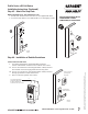
Profile Series v.G1 Exit Device 6 Installation Instructions for Rim Type Exit Device 8877/8878 IMPORTANT: BEFORE STARTING • This device is non handed • Door should be fitted and hung • Verify box label for size of exit device, function and hand Step #1 – Exit Hardware & Door Prep Inside Left Hand Reverse Bevel "LHRB" Right Hand Reverse Bevel "RHRB" Outside 1. If using a mullion, install in frame. 2.
Profile Series v.G1 Exit Device Installation Instructions (Continued) Step #3 – Attach Fire Stop Plate NOTE: Required for 12- Fire Rated doors only 1. Drill (2) 1/8" diameter holes if the door is not supplied with them 2. Secure fire stop plate to door with (2) #8 x 1/2" self tapping screws Non Fire Rated Exterior DoorsInstall Weather Conduit (P/N 52-2847) as shown below 1-1/2'' Dia. 7/8'' Outside of door Insert connector and wires 1.
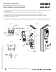
Profile Series v.G1 Exit Device Rim Installation Instructions (Continued) Step #5 Installation of Inside Escutcheon 1. Connect ground wire to terminal E3 (Fig. 1), keypad harness to controller (Fig. 2), and ET motor harness to motor connector (Fig. 3). 2. Place extra wire inside door hole and/or outside escutcheon being careful not to pinch wires. 3. Connectors go on only one way, do not offset connector and be sure they are completely seated. 4.
Profile Series v.G1 Exit Device Rim Installation Instructions (Continued) Battery keeper Note: For RF Technology versions (G1-TU, G1-TP, G1-TA) refer to Section 9 when installing/removing battery keeper. Battery cover Security screw Security tool 01-0297 included Fig. 4 - Polarity + + + - + + + - 2. Install battery keeper clip by inserting tabs into bottom slots first (Fig. 6). To remove keeper, pull on top tab. For RF Technology version refer to Section 9. + Polarity 3.
Profile Series v.
Profile Series v.G1 Exit Device Mortise Installation Instructions (Continued) Step #2 – Install Outside Trim, Exit Chassis and Cylinder B. Exit Chassis: 1. Route “ET” harness along track cutout for wood doors and access hole for metal doors 2. Mount exit chassis carefully. Do not pinch harness wires 3. Position exit chassis on door with lever arm under rear section of mortise lock 4. Using (2) 1/4-20 x 2-3/8" flat head screws attach chassis to “ET” control 5.
Profile Series v.G1 Exit Device Mortise Installation Instructions (Continued) Step #3 – Attach Fire Stop Plate NOTE: Required for 12- Fire Rated doors only 1. Drill (2) 1/8" diameter holes if the door is not supplied with them 2. Secure fire stop plate to door with (2) #8 x 1/2" self tapping screws Non Fire Rated Exterior DoorsInstall Weather Conduit (P/N 52-2847) as shown below CL OF 1-1/2" Dia. 1-1/2" Dia. (2) 1/8" Dia.
Profile Series v.G1 Exit Device Mortise Installation Instructions (Continued) Step #5 – Installation of Inside Escutcheon 1. Connect ground wire to terminal E3 (Fig. 1), keypad harness to controller (Fig. 2), and ET motor harness to motor connector (Fig. 3). 2. Place extra wire inside door hole and/or outside escutcheon being careful not to pinch wires. 3. Connectors go on only one way, do not offset connector and be sure they are completely seated. 4.
Profile Series v.G1 Exit Device 8 Operational Check 1. For devices without cylinder go to step 4 2. For devices with cylinders, insert key into cylinder and rotate 3. The key will retract the latch, the key should rotate freely 4. Depress inside rail to retract latch 5. Enter 1234* to unlock outside lever handle and retract latch 6.