
Operating instructions


9
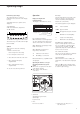
Function Keys (Soft Keys)
The current function of soft keys is
indicated in the bottom line of the display
(footer).
Texts (abbreviations) or symbols can be
displayed.
Texts (Examples)
Cal: Start calibration | adjustment
S ID: Save ID
The function keys are numbered from right
(F1) to left (F6).
Symbols
The bottom line shows the following
symbols:
ooBack to the initial state
(in the Setup menu: exit Setup)
o Go to the higher selection level
O Show sub-items under the active item
Q Move upward in the input |
output window
q Move downward in the input |
output window
l Set the selected menu parameter
F6 F5 F4 F3 F2 F1
Operation
Display for Weights and
Calculated Values
This display is subdivided into 9 areas.
Line for Metrological Data:
When the balance is used in legal metrol-
ogy, the following metrological specifi-
cations of the balance are shown here:
Max Maximum capacity (upper range
limit) of the balance
Min Minimum capacity (lower
range limit) of the balance
e Verification scale interval
d Readability | scale interval
On standard balances, only
Max and d
are displayed.
Operating the Balance as a Legal
Measuring Instrument (Legal for
Trade)
G Remove the cover plate from the back
of the balance housing
G Move switch 1 in the direction
of the arrow
> Switch left:
Standard/not legal for trade
Switch right:
Legal for trade
> Note:
Do not move switch 2
2
1
Line for metrological data
Bar graph
Measured value line
Text line
Soft key labels
Plus/minus sign Unit
Stability indicator Tare memory
Calculated value
Application pictograms
Bar Graph:
The bar graph indicates how much of the
balance’s capacity is “used up” by the
current load; during checkweighing, it
indicates the control limits.
The following symbols may be displayed:
0% Lower load limit
100% Upper load limit
Bar graph showing 10% intervals
- Minimum for checkweighing
= Target for checkweighing
+ Maximum for checkweighing
Plus/Minus Sign, Stability Symbol:
A plus or minus sign (F or H) is shown
here for a weight (or a calculated value,
such as that for counting), or the S
symbol indicating that a verified balance*
has been zeroed or tared.
Line for Measured Values:
This area shows the weighed or calculated
value and the alphanumeric input.
Unit and Stability:
When the balance reaches stability, the
weight unit or calculated unit is displayed
here.
When the
a symbol is displayed here,
the value indicated in the readout cannot
be used in legal metrology.
* = Verification scale interval “e” =
scale interval “d”
Operating Design