Operating Instructions Sartorius IS-X Models IS06BBE-SX, IS2CCE-SX, IS6CCE-HX, IS6CCE-SX, IS12CCE-SX, IS16EDE-HX, IS34EDE-HX, IS64EDESX, IS150IGG-HX, IS300IGG-HX and Verifiable Models Weighing Platforms for Use in Hazardous Areas/Locations 98648-009-42 98648-009-42
Contents Intended Use 2 Intended Use 3 Operating Limits 4 Tables of Specifications 9 Pin Assignment Chart 10 Troubleshooting Guide 11 Accessories (Options) 12 General View of the Equipment 15 Dimensions (Scale Drawings) 20 Declarations of Conformity 26 Certificates for Operation of the Weighing Platform in Hazardous Areas Symbols The following symbols are used in these nstructions: § indicates required steps $ indicates steps required only under certain conditions The series IS...-.
Operating Limits Overload Capacity Thanks to the rugged construction of Sartorius weighing platforms, the weighing system will not be damaged if the maximum weighing capacity is occasionally exceeded. The table below lists the maximum overload capacity of each weighing platform model: IS06BBE-SX.. IS2CCE-SX.. IS6CCE-SX.. IS6CCE-HX..
Tables of Specifications Model IS06BBE-SX IS2CCE-SX IS6CCE-HX IS6CCE-SX IS12CCESX Readability g 0.001 0.01 0.01 0.1 0.1 .......... Weighing capacity g 620 2200 6200 6200 12,000 Max. overload capacity kg 3 12 12 25 25 Tare range (subtractive) g – 620 – 2200 – 6200 – 6200 – 12000 Preload (can be electronically g 93 110 – 1240 1200 compensated without reducing the weighing capacity) Max.
HX-Mode IS16EDE-HX IS34EDE-HX IS64EDE-SX IS64EDE-HX IS150IGG-HX IS300IGG-HX g 0,1 0,1 1 0,1 1 2 kg 16 34 64 64 150 300 kg 130 130 130 130 600 600 kg – 16 – 34 – 64 -64 – 150 -300 Preload (can be electronically compensated kg 4 4 13 13 20 60 without reducing the weighing capacity) Max. preload at start of kg ca. 19 ca. 21 ca.
IS „-.XCE“ Series Verifiable Models Model Readability Weighing capacity Max. overload capacity g g kg IS06 BBE-SXCE 0.001 620 3 IS2 CCE-SXCE 0.01 2200 12 IS6 CCE-HXCE 0.01 6200 12 Tare range (subtractive) g – 620 – 2200 – 6200 Preload (can be electronically compensated) g 93 110 – .......... without reducing the weighing capacity) Max. preload at start of g 110 1300 5200 isoTEST calibration/adjustment (weighing inst.
Verifiable Models, IS Series Readability in g Weighing capacity in kg Max. overload capacity in kg Tare range (subtractive) in kg IS16EDE-HXCE IS34EDE-HXCE IS64EDE-SXCE IS150IGG-HXCE IS300IGG-HXCE 0,1 0,1 1 1 20 16 34 64** 150** 300** 130 130 130 600 600 – 16 – 34 – 64 – 150 -300 Preload (can be electronically compensated in kg 4 4 13 20 20 without reducing the weighing capacity) Max. preload at start of ca. 19 ca. 21 ca. 45 – isoTEST calibration/adjustment (weighing inst.
Pin Assignment Chart Female Interface Connector: 14-contact round female connector with screw lock hardware for cable gland Pin Assignments Platform: Zener barrier (output in safe area) YDI01-Z, YDI02-Z, YDI03-Z: 14-pin 12-pin Signal RS-2321) Signal RS-485 Round male connector Barrier (SBI and xBPI) (xBPI) G A Control output „heavier“ Control output „heavier“ K B Data output (TxD) RxD – TxD – N J C Data input (RxD) RxD – TxD – P N D Data t
Troubleshooting Guide Problem Possible cause(s) Solution No segments are shown No AC power is available Check the AC power supply; connect on the display The power supply or AC adapter the power supply/AC adapter to power is not connected Device not used > 5 minutes Turn on the display and control (now in stand-by mode) unit/indicator using the On/Off switch Weight display shows “ H“ The load exceeds the wei
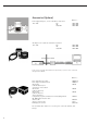
Accessories (Options) Power supply, flameproof, for use in hazardous area/location 100 - 240V EU GB USA/CDN AC adapter for use outside the hazardous area/location 100 - 240V EU GB USA/CDN Order no.: YPS02-XDR YPS02-XGR YPS02-XKR YPS02-ZDR YPS02-ZGR YPS02-ZKR In the safe area (outside the hazardous area/location), accessories can be connected through a Zener barrier. Order no.
General View of the Equipment IS06BBE-SX 1 2 3 4 5 11 10 6 7 9 8 3 12 11 10 9 6 7 8 IS2CCE-SX, IS6CCE-HX, IS6CCE-SX, IS12CCE-SX Pos.
IS16EDE-HX, IS34EDE-HX, IS64EDE-SX 12 Pos.
IS150IGG-HX, IS300IGG-HX 1 2 3 4 7 6 5 Pos.
Dimensions (Scale Drawings) IS06BBE-SX, All dimensions given in millimeters 14
IS2CCE-SX, IS6CCE-HX All dimensions given in millimeters 15
IS6CCE-SX, IS12CCE-SX All dimensions given in millimeters 16
IS16EDE-HX, IS34EDE-HX, IS34EDE-HX, IS64EDE-SX All dimensions given in millimeters 17
All dimensions given in millimeters 18
Declarations of Conformity In 1985, the Council of the European Community approved a resolution concerning a new approach to the technical harmonization and standardization of national regulations. Monitoring compliance with the directives and standards concerning the C marking is governed in the individual EU Member States through the implementation of the EC Directives adopted by the respective national laws.
Certificates Certificates 20 20
Plates and Markings – IS... -.CE + Terminals Note: Protective seals of the indicating and operator terminal see belonging manuals. Type BD BF S locked P M unlocked K S M K S Type BF BF Connects to the terminal no. (nur bei Typ SARTOCOWAT) M (only at type SARTOCOWAT) K S alternative M K S S P locked S unlocked unlocked locked For variants for use in hazardous areas Recognizable at a “-XCE“ in the model name PPIS030511e Connects to the terminal no.
Type HA BD locked P S unlocked S T S S S S K M Connects to the terminal no. (only at type SARTOCOWAT) Type HC BF For variants for use in hazardous areas Recognizable at a “-XCE“ in the model name unlocked locked locked unlocked P weighing pan M S S S K Connects to the terminal no.
In connection with terminals types isi10, isi20, isi30, TN (CIS2, CISL2, CIS3, CISL3), TN-X (CIXS3), TN-Pro (CISPRO), YAC01LA, YAC01LP, YAC01FC, YAC02FC or computer (CE) and software Sartorius Win Scale (D09-99.
Circuit: Uo Io Po Co Lo V1 12.6 V 133 mA 1.46 W 1µF 300µH V2 12.6 V 133 mA 1.46 W 1µF 300 µH V3 8.6 V 187 mA 1.51 W 4 µF 300 µH V4 12.6V 150 mA 1.68 W 1 µF 300 µH Power supply YPS02-Z.R II (2) G [EEx ib] IIC II (1) D Non hazardous area Power supply YPS02-X.R Alternative Connection II 2 G EEx d [ib] IIC T4 II 1 D T135°C Circuit: Uo Io Po Co Lo V1 12.6 V 133 mA 1.46 W 1µF 300µH Sartorius cable: type LiYC-Y-CY 4 x 0,5² (permanently installed on power supply; can be flexibly installed) max.
Barrier YDI01-Z II (2) G [EEx ib] IIC up to 7 further units, which have the same type of RS-485 data output connected to this fieldbus Uo Io Po Co Lo RS-485 1) 12 V 82 mA 240 mW 1.41 µF 5,5 mH Data output Ui Ii Pi Ci Li Uo Io Po Barrier YDI03-Z II (2) G [EEx ib] IIC RS-485 only (pins J/K)2) 12,6 V 810 mA 2.5 W 10 nF 0 12.6V 85 mA 270mW Cable: install as stationary and protected equipment ! Maximum cable length 70m for a 10-wire standard cable with a maximum of 200nF/ km and 1mH/km.
43
Hazardous (Classified) Location Class I, Division 1, Groups A,B,C,D Class I, Zone 1, Groups IIA, IIB, IIC Hazardous (Classified) Location Class I,II,III, Division 1, Groups A,B,C,D,E,F,G SARTORIUS FC......-.X... Display Unit 13) 3) SARTORIUS Power Supply YPS02-XKR 4) 7) AC Supply Canada: Group A is excluded! SARTORIUS FC...BBE-.X.... or FC...CCE-.X.... or 13) 3) IS...CCE-.X.... .....EDE-.X.... OR 10) IS...BBE-.X....
Hazardous (Classified) Location Class I,II,III, Division 1, Groups A,B,C,D,E,F,G Class I, Zone 1, Groups IIA, IIB, IIC Hazardous (Classified) Location Class I,II,III, Division 1, Groups A,B,C,D,E,F,G SARTORIUS FC......-.X... Display Unit 13) 3) SARTORIUS Power Supply YPS02-XKR 4) 7) AC Supply Canada: Group A is excluded! SARTORIUS OR 10) FC...EDE-.X.... or IS...EDE-.X.... or 13) 3) IS...IGG-.X....
Hazardous (Classified) Location Class I,II,III, Division 1, Groups A,B,C,D,E,F,G Class I, Zone 1, Groups IIA, IIB, IIC Hazardous (Classified) Location Class I,II,III, Division 1, Groups A,B,C,D,E,F,G SARTORIUS FCA...EDE-.X....or 3) FCB...EDE-.X....or FCA...IGG-.X.... or 13) FCB...IGG-.X....
ENTITY DATA FOR TERMINAL: Data Output (Pos. 5) Input Parameters : RS232 RS422 RS485 (combined circuits): (Pin A/J/K/N/M): Ui = 12.6 V Ui = 25,2 V ** Ii = 340 mA * Pi = 1.08 W Ci = 2 nF Li = 15 µH (combined circuits): (Pin A/B/C/E/F/G/J/K/M/N): Ui = 7.5 V Ii = 500 mA * Pi = 900 mW Ci = 5.5 µF Li = 17 µH (combined circuits): (Pin J/K/L/M): Ii = 810 mA * Pi = 2.5 W Ci = 12 nF Li = 15 µH Pi = 30 mW Ci = 4 nF Ci = 4 nF Li = 0 Li = 0 Pi = 265 mW Ui = 14.
1) In the USA: The installation must be in accordance with the National Electrical Code ®, NFPA 70, Article 504 or 505 and ANSI / ISA-RP 12.6. In Canada: The installation must be in accordance with the Canadian Electrical Code ®, Part1, Section 18. 2) The apparatus must not be connected to any device that uses or generates in excess of 250Vrms or DC. 3) In the USA: The apparatus must be connected to a suitable ground electrode per National Electrical Code ®, NFPA 70, Article 504 or 505.
Sartorius Industrial Scales GmbH & Co. KG Leinetal 37120 Bovenden, Germany Phone +49.551.308.0 Fax +49.551.309.83.190 www.sartorius.com Copyright by Sartorius, Goettingen, Germany. No part of this publication may be reprinted or translated in any form or by any means without prior written permission from Sartorius. All rights reserved. The status of the information, specifications and illustrations in this manual is indicated by the date given below.