Operating Instructions Sartorius Midrics® 1| Midrics® 2 Models MW1 | MW2 Complete Scales 98648-014-94
Intended Use – – – – Midrics® 1 and 2 are rugged complete scales for the demanding area of daily quality control.
Contents 2 Intended Use 4 Warnings and Safety Precautions 4 4 4 4 4 5 6 6 Getting Started Unpacking the Midrics Equipment Supplied Installation Conditioning the Scale Connecting the Scale to AC Power Leveling the Weighing Platform Operating Limits 7 7 7 7 General View of the Equipment Display and Keypad Back Panel Weighing Platform 8 8 8 9 11 12 12 12 12 Operating Design Keypad Keypad Input Input Through the Digital Control Port Measured Value Display Display of Measured and Calculated Values Sav
Warnings and Safety Precautions Safety Information § To prevent damage to the equipment, please read these operating instructions carefully before using your scale. Getting Started The complete scale is available in various versions. If you have ordered special options, the display and control unit is equipped with the required features at the factory.
Connecting the Scale to AC Power § Check the voltage rating and the plug design. $ The scale is powered through the pre-installed power cord. The power supply is built into display and control unit, which can be operated with a supply voltage of 100V to 240V. Make sure that the voltage rating printed on the manufacturer's ID label is identical to that of your local line voltage.
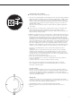
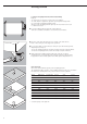
Getting Started Leveling the Weighing Platform (Verified Models Only) Purpose: – To compensate for uneven areas at the place of installation – To ensure that the equipment is placed in a perfectly horizontal position for consistently reproducible weighing results Always level the weighing platform again any time after it has been moved to a different location. § Level the weighing platform using the four leveling feet. Turn the feet until the air bubble is centered in the level indicator.
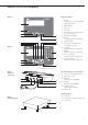
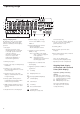
General View of the Equipment Midrics 1 Display and Keypad 1 Display (for details, see the chapter entitled “Operating Design") 2 On/standby key 3 Zero key 1 2 4 Tare key 5 Function key (e.g.
Operating Design Keys Operation of the Midrics® 1 or Midrics® 2 scale involves just a few keys. These keys have one function during measurement and another during configuration. Some of the keys have one function when pressed briefly and another activated by pressing and holding the key for longer than 2 seconds. If a key is inactive, this is indicated as follows when it is pressed: – The error code “———-” is displayed for 2 seconds. The display then returns to the previous screen content.
Numeric Input Through the Keypad (Midrics 2 only) § To enter numbers (one digit at a time): Press 0, 1, 2 …9 § To save input: press the required key (e.g.
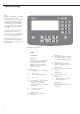
Operating Design 1 2 3 4 5 17 6 7 16 15 14 8 12 13 Display in Weighing Mode The illustration above shows all display segments and the symbols and other elements used during normal weighing operation. 1. Bar graph – Shows the percentage of the weighing platform's capacity that is “used up" by the load on the scale (gross value), or – Shows the measured value in relation to a target value (with the Checkweighing or Classification application) 11 10 9. Numeric display; e.g.
Bar graph The bar graph shows the percentage of the weighing platform's capacity that is “used up" by the load on the scale (gross value). 0% 100% Lower limit Upper limit The following symbols indicate tolerance levels for Checkweighing: Saving Data in Weighing Mode All of the application parameters saved (e.g.
Operating Design Display of menu settings: Text menu (example) Operating Menu Navigation The keys below the readout let you navigate the menu and define parameters for configuration. Opening the Menu Press the e key to switch the Midrics off and then on again; while all segments are displayed, press the ) key briefly.
Configuration – – – – – You can configure the Midrics scale by selecting parameters in the operating menu. The parameters are combined in the following groups (this is the highest menu level): Application parameters Fn key function Device parameters (“Setup") Device-specific information (“Info") Language Setting the Language e Switch on the scale When the scale is used in legal metrology, not all parameters can be accessed. ) While all segments are lit, press the ) key Example: Selecting “U.S.
Entering or Changing the Password Example: Assign a password (in this example, AB2) to protect the application program settings APPL and the device parameters SETUP from unauthorized changes e 1. Switch on the scale p, p, p 9. Enter the second character using the p and k keys (in this example: B) ) 2. While all segments are lit, press the ) key ) 10. Save the character k, k, k, 11. Enter the third character using the p and k keys (in this example: 2) ) 12. Save the password ( 13.
Operating Menu Overview You can configure the Midrics to meet individual requirements by entering user data and setting selected parameters in the operating menu. 1st level display 2nd level display Menu levels are identified by texts, and numeric codes identify the individual settings.
Operating Menu = Setting/function available on Midrics 2 only * Factory setting Menu Application Programs appl W Basic weighing function 3.5. 3.5.1* 3.5.2 3.5.3 3.5.4 3.5.5 3.5.6 3.5.7 3.5.8 3.5.9 3.5.10 Minimum load for automatic taring and automatic printing 1 digit 2 digits 5 digits 10 digits 20 digits 50 digits 100 digits 200 digits 500 digits 1000 digits 3.7.1* 3.7.2 Automatic taring: first weight tared Off On 9.1.1 9.1.2* Factory settings for all application programs Yes No 3.7. 9.1.
appl Z nm Neutral Measurement 3.5. Minimum load for automatic taring and automatic printing Numeric menu as for Weighing 3.6. Minimum load for initialization Numeric menu as for Counting 3.7. 3.7.1* 3.7.2 Automatic taring: first weight tared Off On 3.8.1 3.8.2* Start application and load most recent application data when the Midrics is switched on Automatic (on) Manual (off) 3.9.1* 3.9.2 3.9.3 3.9.
appl V Averaging (Animal Weighing) 3.21. 3.21.1* 3.21.2 Static display of result after load removed Display is static until unload threshold reached Display is static until c is pressed 9.1.1 9.1.2* Factory settings for all application programs Yes No 9.1. O Checkweighing 3.5. Minimum load for automatic taring and automatic printing Numeric menu as for Weighing 3.6. Minimum load for initialization Numeric menu as for Counting 3.7. 3.7.1* 3.7.2 Automatic taring: first weight tared Off On 3.8.
appl Classification W 3.8. 3.8.1 3.8.2* Start application and load most recent application data when the Midrics is switched on Automatic (on) Manual (off) 4.3.1* 4.3.2 Activate control line for “Set” as: “Set” output Ready to operate (for process control systems) 4.7.1 4.7.2 4.7.3* Activation of outputs Off Always active Active at stability 4.8.1* 4.8.2 Number of classes 3 classes 5 classes 4.9.1* 4.9.2 Parameter input Weight values Percentage 4.10.1* 4.10.2 Automatic printing Off On 9.1.1 9.
appl R Net-total Formulation (2nd Tare Memory) 3.5. Minimum load for automatic taring and automatic printing Numeric menu as for Weighing 3.6. Minimum load for automatically saving/transferring values Numeric menu as for Counting 3.7. 3.7.1* 3.7.2 Automatic taring: first weight tared Off On 3.17.1 3.17.2* 3.17.
Device Parameters Setup Password prompt displayed if a password is configured wp-1 1 Weighing platform 1 (Display designation of this menu level: 1) 1.1.1 1.1.2* 1.1.3 1.1.4 Adapt weighing instrument to ambient conditions (adapt filter) Very stable conditions Stable conditions Unstable conditions Very unstable conditions 1.2.1* 1.2.2 1.2.3 1.2.4 Application filter Final readout Filling mode Low filtering Without filtering 1.3.1 1.3.2 1.3.3 1.3.4* 1.3.5 1.3.
Setup wp-1 1 1.9.1* 1.9.3 1.9.10 Calibration and adjustment External calibration/adjustment; default weight External calibration/adjustment; weight can be selected under menu item 1.18.1 No function when you press and hold ) > 2 sec 1.10.1 1.10.2* Calibration/adjustment sequence Calibration with automatic adjustment Calibration with adjustment triggered manually 1.11.1 1.11.2* Zero-setting range 1 percent/max. cap. 2 percent/max.cap. 1.12.2 1.12.3 1.12.4* Initial zero-setting range 2 percent/max.
Setup Com1 2 Interface port 1 (optional) (Display designation of this menu level: 2) off* Off datProt Data protocol sbi* SBI: standard version 5.1. 5.1.1 5.1.2 5.1.3 5.1.4* 5.1.5 5.1.6 5.1.7 5.1.8 Baud rate 150 baud 300 baud 600 baud 1200 baud 2400 baud 4800 baud 9600 baud 19,200 baud 5.2.2 5.2.3 5.2.4 5.2.5 Parity Space2) Odd Even None3) 5.3.1* 5.3.2 Number of stop bits 1 stop bit 2 stop bits 5.4.1 5.4.3* Handshake mode Software handshake Hardware handshake, 1 character after CTS 5.6.1* 5.6.
Setup Com1 2 datProt SMA SMA interface function 5.1. 5.1.1 5.1.2 5.1.3 5.1.4 5.1.5 5.1.6 5.1.7* 5.1.8 Baud rate 150 baud 300 baud 600 baud 1200 baud 2400 baud 4800 baud 9600 baud 19,200 baud 5.2. through 5.6. Numeric menu as for SBI Printer Printer configuration YDP01IS YDP01IS line* label lab ff Strip printer Label printer Label printer with manual feed YDP02 YDP02 variants 5.1.4* 5.1.5 5.1.6 5.1.7 Baud rate 1200 baud 2400 baud 4800 baud 9600 baud 5.2.2 5.2.3* 5.2.4 Parity Space Odd Even 5.
Setup Com1 2 Printer Uni-pri Universal interface 5.1.1 5.1.2 5.1.3 5.1.4 5.1.5 5.1.6 5.1.7* 5.1.8 Baud rate 150 baud 300 baud 600 baud 1200 baud 2400 baud 4800 baud 9600 baud 19,200 baud 5.2.2 5.2.3 5.2.4 5.2.5* Parity Space1) Odd Even None2) 5.3.1* 5.3.2 Number of stop bits 1 stop bit 2 stop bits 5.4.1* 5.4.3 Handshake mode Software handshake Hardware handshake, 1 character after CTS 5.6.1 5.6.2* Number of data bits 7 data bits 8 data bits 5.1. 5.2. 5.3. 5.4. 5.6.
Setup unicom 3 Interface port 2 (Optional) (Display designation of this menu level: 3) off* Off datprot Data protocol sbi* SBI: standard version 5.1. through 9.1. Numeric menu as for COM1 bpi-232 XBPI-232 bpi-485 XBPI-485 0 to 31 Network address: From 0 to 31 inclusive sma SMA interface function 5.1. through 5.6. Numeric menu as for COM1 ETHER src-ip src.name lis.port supnet gate-ip dest-ip dest.por Source IP: 192.168.0.
Setup uniCom1 3 Second interface (optional) Printer Printer configuration YDP01IS YDP01IS line* label lab ff Strip printer Label printer Label printer with manual feed YDP02 YDP02 5.1. through 5.4. Numeric menu as for COM1 YDP03 YDP03-0CE 5.1. through 5.4. Numeric menu as for COM1 YDP02IS YDP02IS line* label Strip printer Label printer Uni-pri Universal interface 5.1. through 5.6.
Setup ctrl io 4 Control inputs/outputs (Display designation of this menu level: 4) ctr inp Control inputs 8.4.1* 8.4.2 8.4.3 8.4.4 8.4.5 8.4.7 8.4.8 8.4.9 8.4.10 8.4.11 8.4.
Setup barcode 5 Bar code (Display designation of this menu level: 5) ref* tare* 1D1 Input Header ext.keyb Store value as reference weight Store as tare value (i.e., tare the scale) Store value as ID code 1 Enter value on display (triggered when a key is pressed) Store value as tare or ID code, depending on bar code header External computer keypad prtprot 6 Printouts (Display designation of this menu level: 6) 7.4.1 (blank) 7.4.2 (blank) 7.4.3 (ID 1) 7.4.4 (ID 2) 7.4.5 (ID 3) 7.4.
Setup prtprot 6 7.10.1* 1) 7.10.2* 1) 7.10.4* 1) 7.10.5* 1) 7.10.7 1) 7.10.8 1) Optional “UniCOM” interface Print results when c pressed in Totalizing and Net-total applications Header lines 1, 2 (content: see menu codes 7.4.x) Date and time Weighing instrument designation Result from the application program 2 additional blank lines 3 additional blank lines 7.13.1 7.13.2 7.13.3 GMP data record or printout Off On for one result On for multiple result 7.14.1* 7.14.
Setup time Time (optional) Format for setting the time (example): 10.07.41 (hours.minutes.seconds) date Date (optional) Format for setting the date (example): 01.05.07 (day.month.year); U.S. mode: (month.day.year) code Password Set, change and delete password here. Max. 8 characters); example: 12345678 Device information Info Service Service information 10.04.02 1 term Display and control unit (“terminal”) 1: MW2P1 2: 10405355 3: 01.24.01 4: 00.37.01 5: 52 6: 1 50 7: 8.
Operation Basic Weighing Function Weighing W The basic weighing function is always accessible and can be used alone or in combination with application programs, such as Counting, Checkweighing, Weighing in Percent, etc. Features – Zero the scale ( Automatic Taring The first weight on the scale that exceeds the preset minimum load is stored in the tare memory at stability. The values for subsequent loads are stored as weight values.
Example with Midrics 2: Switch on; zero; tare container weight; place sample in container; toggle display to gross weight, second weight unit or 10-fold higher resolution; print results. e 1. Switch on the scale Display with tared scale and sample in container All display segments are shown for about 1 second (self-test) k Display with no load on scale 6. Toggle display; readout depends on your settings: Gross weight (in this example, 50 g for container +120.2 g substrate) ( 2.
Example with Midrics 2 Tare the scale by placing a container on the weighing platform Example with Midrics 2: Enter the tare value using the keypad; print the results e e 1. Switch on the scale The automatic self-test runs. Once a readout is shown, the Midrics is automatically zeroed and ready to operate. Press ( to reset the unloaded weighing platform to zero at any time. 250 2. Enter the tare weight in the current weight unit using the keypad (in this example, 250 g). ) 3. Save the tare weight.
Example with Midrics 2: Weigh with varying tare values; print the results; delete tare values e 1. Switch on the scale The automatic self-test runs. Once a readout is shown, the Midrics is automatically zeroed and ready to operate. Press ( to reset the unloaded weighing platform to zero at any time. Read the net weight p 7. Print the results. G# + 6.433 kg T + 4.183 kg PT2 + 0.250 kg N + 2.000 kg -------------------2. Place empty container on the platform ) 3.
Calibration and Adjustment Features You can configure the parameters listed below in the operating menu. Which of the features listed here are available depends on the connected weighing platform. Purpose Perform calibration to determine the difference between the value displayed and the actual weight on the platform. Calibration does not entail making any changes within the weighing instrument.
Example: External calibration and manual adjustment with default weights (weighing parameters: factory settings) ( 1. Zero the scale. J 2. Start calibration (e.g., after calibration prompt: flashing WP symbol). c.ext.def is shown for two seconds. The difference between measured value and the true mass is shown with a plus or minus sign. ) You are prompted to place the required weight on the platform (e.g.
Data ID Codes Midrics 2 only: You can assign codes (such as product name, batch number, etc.) for identification of measured values on printouts. Example with Midrics 2: Enter ID code names. Enter “Batch no." and “Cust." as names for ID codes 1 and 2. e 1. Switch on the scale ) 2. While all segments are lit, press the ) key Features – Assign up to four ID codes. – Assign both a name and a value for each ID code. – The name is left-justified and the value is right-justified on the printout.
4. Place sample on the platform p, p, p ) 9. Enter the first character using the p and k keys (in this example, the first character is “C") 10. Save the character p ( ) 12. Exit the active submenu to configure other menu settings, or ID code 2 ID2 123 24.02.2006 10:09 ------------------Ser.no 12345678 G# + 1083 g T + 0000 g N + 1083 g 6. Deleting ID codes: ID codes are deleted one at a time; for example, when the weighing operations have been completed 11.
Application Programs Applications: Overview Midrics 1 Midrics 2 Keypad 5 keys 11 keys + numeric keypad Display 14-segment 14-segment plus application symbols X X X X X X X X X Applications Basic weighing Averaging (animal weighing) Print/send data record to peripheral device Label printing Counting Totalizing Checkweighing Batching to a target value X Functions Zero-setting Taring Date and time ID codes (4 codes, 40 char.
Application: Counting Z With the Counting program you can determine the number of parts that each have approximately equal weight.
Application: Counting Z Preparation § Switch on the scale: Press e § While all segments are lit, press the ) key § Select the Application menu: Press k repeatedly until APPL is displayed § Open the Application menu: Press the ) key § Select the Counting application: Press the k key repeatedly until the desired menu item is displayed and press ) to open the submenu Application Parameters: Counting 3.5. 3.6. Minimum load for automatic taring and automatic printing 3.5.1* 1 digit 3.5.2 2 digits 3.5.
Example: Determining the number of uncounted parts. Settings (changes in the factory settings required for this example): Setup: Application: Counting Setup: PRTPROT (printout): 7.7.x (COM1) (see “Configuration” for options) In this case, reduce the minimum load setting or increase the number of parts in the container and reset the reference sample quantity accordingly. 1. Place empty container on the platform 5. Add more parts to the container ) 2.
Application: Neutral Measurement Z nM With this application you can use your weighing platform to measure the length, surface and volume of parts that have roughly the same specific weight. The o symbol is displayed as the weight unit.
Minimum Load The minimum load required for initialization of the weighing platform is configured in the operating menu under: Appl Z nM: 3.6. Once the limit is exceeded by the load, initialization can begin.
Example: Measuring 25 m electrical cable. Settings (changes in the factory settings required for this example): Setup: Application: Neutral Measurement Setup: PRTPROT (printout): 7.7.x (COM1) (see “Configuration” for options) 1. Place empty container on the platform ) 248 O 46 2. Tare the scale Note: If the automatic tare function is enabled, you do not need to press the ) key to tare the scale; the tare weight is saved automatically when you place the container on the platform 3.
Application: Averaging (Animal Weighing) V With the Averaging application, you can use your weighing platform for calculating weights as the average of a number of individual weighing operations. This function is used to determine weights under unstable ambient conditions or for weighing unstable samples (such as live animals). Features – Averaging starts manually or automatically. Configuration: appl V: 3.18.
Application Parameters: Averaging (Animal Weighing) 3.5. 3.6. Minimum load for automatic taring and automatic printing 3.5.1* 1 digit 3.5.2 2 digits 3.5.3 5 digits 3.5.4 10 digits 3.5.5 20 digits 3.5.6 50 digits 3.5.7 100 digits 3.5.8 200 digits 3.5.9 500 digits 3.5.10 1000 digits Minimum load for automatic start 3.6.1* 1 digit 3.6.2 2 digits 3.6.3 5 digits 3.6.4 10 digits 3.6.5 20 digits 3.6.6 50 digits 3.6.7 100 digits 3.6.8 200 digits 3.6. 9 500 digits 3.6.10 1000 digits 3.7.
Example: Measuring the weight of one mouse. Settings (changes in the factory settings required for this example): Setup: Application: Animal weighing Setup: PRTPROT (printout): 7.7.x (COM1) (see “Configuration” for options) The averaging routine does not begin until the fluctuation in weight value remains below a defined threshold over three consecutive measurements. The number of subweighing operations remaining is shown in the numeric display.
Application: Weighing in Percent L With the Weighing in Percent application, you can have the value of the weight on the platform displayed as a percentage calculated in relation to a defined reference weight. The L symbol is displayed in place of the weight unit.
Minimum Load The minimum load required for initialization of the weighing platform is configured in the operating menu under: Appl L: 3.6. Once the limit is exceeded by the load, initialization can begin.
Example: Weighing in 100% of a sample material. Settings (changes in the factory settings required for this example): Setup: Application: Weighing in percent Setup: PRTPROT (printout): 7.7.x (COM1) (see “Configuration” for options) If the weight is too light, the error code Inf 29 is shown on the main display. Reduce the minimum load setting. 1. Place empty container on the platform ) 3. Add reference material in accordance with reference percentage (in this example, 85 g, = 10%) O 52 5.
Application: Checkweighing O With the Checkweighing application, you can check whether the sample on the weighing platform matches a target value, or lies within a given tolerance range. Checkweighing also makes it easy to fill sample materials to specified target weight. Features – Enter the nominal or target weight (setpoint) and the tolerance range delimiters either using the keypad or by saving the weight value from a load on the platform.
Minimum Load The minimum load required for automatic taring of the container weight on the platform (first weight), or for automatic printout of results, is configured in the operating menu under: Appl O: 3.5. You can choose from 10 settings, ranging from – – – – Digital Input/Output Interface + Optional I/O The Checkweighing application supports the digital input/output interface.
Example: 1 Checkweighing samples with a target weight of 1250 g and a tolerance range from –10 g to +30 g Settings (changes in the factory settings required for this example): Setup: Application: Checkweighing Setup: PRTPROT (printout): 7.7.x (COM1) (see “Configuration” for options) 1280 O O Save value for upper limit 1. Enter the initial target and tolerance limit values 7. Weigh samples p 8.
Application: Classification W With the Classification application, you can determine whether the weight of a given sample lies within the limits of a defined weight class. Features – Classification with 3 or 5 weight classes. Configure in Setup under: Appl W: 4.8. – Enter the upper class limits using the keypad or by saving weight values from a load on the platform – Enter the upper limits of weight classes as absolute values or as a percentage of deviation from the upper limit of Class.
Minimum Load The minimum load for the first class is configured in the operating menu, under: Appl W: 3.6. Once the limit is exceeded by the load, initialization can begin. Once the application is initialized, a weight value below the minimum load is designated Class 0; no class is displayed. The minimum load required for automatic taring of the container weight on the platform (first weight), or for automatic printout of results, is configured in the operating menu under: Appl W: 3.5.
Example: Defining three classes. Settings (changes in the factory settings required for this example): Setup: Application: Classification Setup: PRTPROT (printout): 7.7.x (COM1); printout for app; then select desired line items (see “Configuration” for options) O 1. Begin input of class delimiters 6. Place the sample on the weighing platform 110 2. Enter the upper limit for Class 1 via the keypad (in this example, 110 g) O 3. Save the upper limit for Class 1 130 4.
Application: Totalizing L With the Totalizing application, you can add weight values together in the totalizing memory. In addition to weight values, the number of individual values added to memory is also saved (transaction counter). Features – Totalize up to 999 individual weights Save values automatically: – Save both net values and calculated values (if available). Configuration: Appl L: 3.16. – Save weight values and calculated values from Counting, Weighing in Percent or Checkweighing.
Application Parameters: Totalizing 3.5. 3.6. 3.7. 3.8. Minimum load for automatic taring and automatic printing 3.5.1* 1 digit 3.5.2 2 digits 3.5.3 5 digits 3.5.4 10 digits 3.5.5 20 digits 3.5.6 50 digits 3.5.7 100 digits 3.5.8 200 digits 3.5.9 500 digits 3.5.10 1000 digits Minimum load for automatically saving/transferring values 3.6.1* 1 digit 3.6.2 2 digits 3.6.3 5 digits 3.6.4 10 digits 3.6.5 20 digits 3.6.6 50 digits 3.6.7 100 digits 3.6.8 200 digits 3.6.9 500 digits 3.6.
Example: Totalizing weight values. Settings (changes in the factory settings required for this example): Setup: Application: Totalizing Setup: PRTPROT: 7.7.x (COM1 interface) then select the desired line items Setup: PRTPROT: 7.9.x (“Print when CF pressed") then select the desired line items 4. Place the weight on the weighing platform 1. Place the first weight on the weighing platform Weight value is displayed Weight value is displayed O G# T N n 2.
Application: Net-total Formulation R With the Net-total Formulation application, you can weigh in different components up to a defined total. Each component is saved in a net-total memory. Features – Weigh in up to 999 components in series – Net-total formulation cannot be combined with other applications – Current component number displayed in the text line (indicating the component to be added) – Toggle the display between “component mode" and “additive mode" by pressing w.
Example: Weighing in 3 components of a formulation recipe. Settings (changes in the factory settings required for this example): Setup: Application: Net-total Formulation Setup: PRTPROT: 7.7.x (COM1 interface) “Printout when value is saved”; then select the desired line items Setup: PRTPROT: 7.9.x “Print when CF pressed" then select the desired line items 1. Place empty container on the platform ) 2.
The weighing platform is tared and the component counter value is increased by one. Prompt to fill and save the second component is shown. 8. Add the third component to the container, bringing the total up to the desired target (in this example, 2000 g). 5. Add the second component to the container (in this example, 525 g) The total weight is displayed The weight of the second component is displayed O Cmp003+ O Cmp002+ 0.525 kg 7.
Configuring Printouts Purpose You can specify which data items are included on printouts. When using the Totalizing or Net-total Formulation application, you can also define which parameters are included in the “Total" data record when the c key is pressed. In the Setup menu under “Printout" you can configure an individual, component or total data record that contains all data items activated for the application program currently in use.
Configuring Printouts Configuring the Data Interface as a Printer Port (printer) You can connect one or two strip printers or one or two label printers to the Midrics. Configure the COM1 and UniCOM interfaces as printer ports under the “Printer" menu item. There are several actions that generate the command for sending data to the printer port: – Pressing the p key. If the operating menu is active, all menu settings under the active menu level are printed. – On receipt of the SBI command “Esc k P _".
GMP-compliant Printouts When the corresponding menu item is active, the measured result is bracketed on the printout by a GMP header and a GMP footer (GMP = “Good Manufacturing Practice"). The GMP header precedes the first measured result. The GMP footer is printed either after each measured result (“ISO/GLP/GMP: For 1 application result," menu item 7.13.2), or after the last result in a series of measurements (“ISO/GMP/GLP: For several application results," menu item 7.13.3).
Sample Printouts For details on the individual information blocks, see “Configuring Printouts" above. For details on configuring the header lines, refer to the chapter describing the particular application. Weighing Application There is no data for the “initialization data" block. If this block is enabled for the printout, a blank line is output. HEADER LINE 1 HEADER LINE 2 14.01.2006 09:43 -------------------G# + 1.402 kg T + 0.200 kg N + 1.
Classification Application The “Initialization data" block contains the upper limits of Classes 1 through 4. The “Results" block contains gross, net and tare weights, as well as the class that the sample belongs to (1 through 5, where Class 5 means that the upper limit of Class 4 was exceeded). -------------------Lim1 + 10.000 kg Lim2 + 11.000 kg Lim3 + 12.000 kg Lim4 + 13.000 kg G# T N + + + 9.700 kg 0.000 kg 9.
Configuring Printouts Individual printout (menu item 3.17.2) The entire standard printout is generated for each component. Example: Print second transaction: HEADER LINE 1 HEADER LINE 2 14.01.2006 09:43 ------------------G# + 2.400 kg T + 0.200 kg N + 2.200 kg n 2 Standard printout The transaction counter value is not printed. Example: Print second transaction: G# T N + + + 2.400 kg 0.200 kg 2.200 kg Print menu parameters: All active menu item settings below the active menu level are printed.
Data Interface (Optional) For COM1 Standard equipment: RS-232 SBI/XBPI protocol, Option A11: Option: “RS-232 clock:" Option A31 Computer with serial RS-232 input port printer: YDP04IS YDP02IS YDP12IS YDP03-0CE YAM01IS external Alibi memory YBT01 external Bluetooth adapter YRD02Z second display USB adapter cable for connecting a computer over USB: YCC01IS As for the RS-232 standard, but includes date/time For UniCOM Male connector: For RS-232 / RS-422 / RS-485 analog output port / digital I/O Ethernet:
Error Codes Error codes are shown on the main display. “Err" codes are shown continuously; “Inf" messages are displayed for 2 seconds, after which the program returns automatically to the weighing mode.
Care and Maintenance Service Regular servicing by your customer service partner will ensure the continued weighing accuracy of your scale. The optimum length of the service interval depends on the operating conditions at the place of installation and on your tolerance requirements. Repairs ! Disconnect defective equipment from power immediately (unplug the equipment from the wall outlet (mains supply)).
Overview Specifications Maximum readability Accuracy class Verification scale intervals (example) Digital protective interface Data interface Display Ambient conditions: Operating temperature range Humidity 15,000 scale intervals (in not legal metrology) l and m (for “..-.CE" models) < 3000e (single-range scale) or 2+ 3000e (multiple-range scale) acc.
Dimensions (Scale Drawings) a b C e d Standard and Stainless Steel Versions Model Length Width Height Standard version Spacing between leveling feet Standard version c (mm) 85...100 96...111 110...125 Height Stainless steel version c (mm) 85...100 96...111 110...
Accessories/Options Accessories/Options Printer and printer accessories: Verifiable printer with functions for date, time and statistical evaluations; connecting cable required YCC02-D09F6 Printer paper for data printer (5 rolls; length per roll: 50 m) Replacement ink ribbon cartridge for YDP03-0CE/YDP04 YDP03-0CE 6906937 6906918 YDP03-0CE Verifiable strip and label printer with thermal print head, YDP04IS-0CEUV up to 60 mm paper width, with external 100–240V power supply; connecting cable required YCC0
Product Order No. COM1 RS-232 RS-232+CLOCK YDO01M-232 YDO01M-232CLK Optional UniCOM interface Interface module (RS-232) Interface module (RS-485), electrically isolated Digital I/O, 5/5, opto-isol.
Accessories/Options Product Cables Connecting cable with cable gland for YDP12/04IS printers, open cable ends to 9-pin D-Sub male connector; 6 m Connecting cable with cable gland for a YDP03-0CE printer or a computer, open cable ends to 9-contact D-Sub female connector; 6 m Connecting cable with cable gland for accessories, open cable ends to 25-contact D-Sub female connector; 6 m Connecting cable with cable gland, for accessories and IS platforms; open cable ends to 12-contact round female connector; 6 m
Drive-on ramp, painted, for equipment with the following dimensions: Pit frame edges, stainless steel, for equipment with the following dimensions: Weighing platform size in mm 800+ 800 800+1000 1000+ 800 1000+1000 1250+1000 1250+1000 1250+1250 1500+1250 1500+1250 1500+1500 2000+1500 Weighing platform, in mm 800+800 1000+800 1000+1000 1250+1000 1250+1250 1500+1250 1500+1500 2000+1500 Ramp length + width Order no.
Declarations of Conformity In 1985, the Council of the European Community approved a resolution concerning a new approach to the technical harmonization and standardization of national regulations. Monitoring compliance with the directives and standards concerning the C marking is governed in the individual EU Member States through the implementation of the EC Directives adopted by the respective national laws.
C 81
Index Page Page Access code Accessories Animal weighing Applications, technical advice on Automatic shutoff Averaging 14 76–79 17, 47 2 30 17, 47 C marking Calibration/adjustment Checkweighing Classification Cleaning COM1 interface, settings Configuration Configuring printers Connecting the equipment to AC power Counting 80 22, 36 18, 53 18, 56 73 23–25, 71 13 24, 25, 27 5 16, 41 Data interfaces Data output, configuring Data record, settings Data records, samples Date and time, setting Declarations of
Appendix: General Password When you select the Setup menu item, the password prompt is displayed for 2 seconds, and then the cursor flashes in the position of the first character of the password. Repeatedly: k, ); Repeatedly: k, ); Repeatedly: k, ); Repeatedly: k, ); Repeatedly: k, ); Repeatedly: k, ); Repeatedly: k, ); Enter the password – Press k to enter letters and ) to save.
Sartorius AG Weender Landstrasse 94–108 37075 Goettingen, Germany Phone +49.551.308.0 Fax +49.551.308.3289 www.sartorius.com Copyright by Sartorius AG, Goettingen, Germany. All rights reserved. No part of this publication may be reprinted or translated in any form or by any means without the prior written permission of Sartorius AG. The status of the information, specifications and illustrations in this manual is indicated by the date given below.