
Instruction manual


52 April 2012 ARRL – the national association for Amateur Radio www.arrl.org
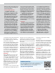
Table 1
ICOM IC-9100, serial number 02001053
Manufacturer’s Specifications Measured in the ARRL Lab
Frequency coverage: Receive, 0.03-60, 136-174, Receive, as specified; transmit, as
420-480, 1240-1320 MHz; transmit, 1.8-2.0, specified, except 5.255-5.405 MHz,
3.5-4, 5.3305, 5.3465, 5.3665, 5.3715, non channelized. The optional UX-9100
5.4035, 7-7.3, 10.1-10.15, 14-14.35, 18.068- is required for 23 cm operation.
18.168, 21-21.45, 24.89-24.99, 28-29.7,
50-54, 144-148, 430-450, 1240-1300 MHz.
Power requirement: 13.8 ±15% V dc; receive, 13.8 V dc; receive 3.2 A (no signal, max
4.5 A (max audio, HF, 50, 144, 430 MHz), audio), 3 A (no signal, max audio,
5.5 A (max audio, 1200 MHz); transmit, 24 A backlight off); transmit, 19.7 A (HF, 144,
(HF, 50, 144, 430 MHz), 9 A (1200 MHz). 430 MHz), 8.4 A (1296 MHz); 54 mA
(transceiver off). Operation confirmed
at 11.4 V dc (89 W output, HF).
Modes of operation: SSB, CW, AM, FM, As specified. The optional UT-121 is
RTTY, DV. required for DV operation.
Receiver Receiver Dynamic Testing
SSB/CW sensitivity: 2.4 kHz bandwidth, Noise floor (MDS), 500 Hz filter,
10 dB S/N: 0.1-29.99 MHz, 0.16 µV; 3 kHz roofing filter:
50-54 MHz, 0.13 µV, 144/430/1200 MHz, Preamp Off 1 2
0.11 µV. 0.137 MHz –122 –131 –135 dBm
0.505 MHz –134 –140 –142 dBm
1.0 MHz –133 –140 –142 dBm
3.5 MHz –134 –142 –144 dBm
14 MHz –133 –141 –143 dBm
50 MHz –130 –140 –142 dBm
144 MHz — — –143 dBm
430 MHz — — –144 dBm
1296 MHz — — –145 dBm
Noise figure: Not specified. Preamp off/1/2: 14 MHz, 13/6/4 dB;
50 MHz, 17/7/5 dB, 144 MHz, 4 dB;
430 MHz, 3 dB; 1296 MHz, 2 dB.
AM sensitivity: 6 kHz bandwidth, 10 dB S/N: 10 dB (S+N)/N, 1 kHz tone, 30%
0.5-1.799 MHz, 12.6 µV; 1.8-30 MHz, 2 µV; modulation, 6 kHz bandwidth:
50-54 MHz, 1.6 µV; 144/430 MHz, 1.4 µV. Preamp Off 1 2
1.0 MHz 1.68 0.72 0.65 µV
3.8 MHz 1.46 0.62 0.56 µV
50.4 MHz 2.51 0.92 0.75 µV
144 MHz — — 0.57 µV
430 MHz — — 0.55 µV
FM sensitivity: 15 kHz bandwidth, 12 dB SINAD: For 12 dB SINAD, 3 kHz deviation,
28-29.7 MHz, 0.5 µV; 50-54 MHz, 0.32 µV; 15 kHz bandwidth:
144/430/1200 MHz, 0.18 µV Preamp Off 1 2
29 MHz 0.56 0.21 0.17 µV
52 MHz 0.70 0.20 0.20 µV
146 MHz — — 0.17 µV
440 MHz — — 0.17 µV
1290 MHz — — 0.15 µV
Spectral display sensitivity: Not specified. Preamp off/1/2, –94/–101/–110 dBm.
†
Blocking gain compression dynamic range: Blocking gain compression dynamic range,
Not specified. 500 Hz bandwidth, 3 kHz roofing filter:
20 kHz offset 5/2 kHz offset
Preamp off/1/2 Preamp off
3.5 MHz 141/139/138 dB 121/111 dB
14 MHz 142/140/134 dB 120/111 dB
50 MHz 139/141/136 dB 119/110 dB
Preamp 2 Preamp 2
144 MHz 130 dB 111/110 dB
430 MHz 119 dB 109/103 dB
1296 MHz 100 dB 95/89 dB
Reciprocal mixing dynamic range: Reciprocal mixing dynamic range,
Not specified. 500 Hz bandwidth, 3 kHz roofing filter:
14 MHz, 20/5/2 kHz offset: 101/80/77 dB.
ARRL Lab Two-Tone IMD Testing See Table 2.
Second-order intercept point: Not specified. Preamp off/1/2, 14 MHz, +65/+65/+65 dBm;
50 MHz, +73/+73/+73 dBm; preamp 2,
144 MHz, +69 dBm; 430 MHz, +90 dBm.
FM adjacent channel rejection: Not specified. Preamp 2: 29 MHz, 81 dB; 52 MHz, 78 dB;
146 MHz, 77 dB; 440 MHz, 66 dB;
1290 MHz, 68 dB.
mode buttons, which are bracketed by the
MENU and FILTER buttons. Given the addition
of the DV/DR button, the ’9100 does not have
separate CW and RTTY mode buttons as on the
’7410. There is a single CW/RTTY key. There
are other accommodations. Take notes!
There will be a quiz.
Since the main receiver’s AF/RF SQUELCH
controls take up the spot where the MIC and
RF PWR controls live on the ’7410, ICOM has
relegated these functions to the row of four
stem controls along the lower apron of the
front panel. The ’9100’s stem controls are
sturdier than the ones on, say, the
IC-756PROIII, but it’s difficult to determine
their relative settings. The other two stem
controls are for CW PITCH and KEY SPEED. A
dab of white paint on the tiny arrow of each
stem would help. The ’9100’s NOTCH control
has migrated to the lefthand side of the panel
to assume the outer ring position of the NR/
NOTCH control, which, in turn, is directly
above the main receiver’s AF/RF SQUELCH
controls.
Topping the column of buttons immediately
to the right of the display window is the
SATELLITE mode button, followed by the
MAIN/SUB (band) selection and SUB buttons.
The SPLIT, A/B and XFC buttons are on the
bottom. A NOR/REV function for inverting
satellite up and downlinks is a secondary
function of the 7/[3] band/keypad button.
Complementing the PBT CLR (passband
tuning clear) button on the right hand side of
the panel is the SUB DIAL button. Its function
is too difficult to explain in a few words and
without the table in the Instruction Manual,
which didn’t do a very good job of explaining
it anyway; the manual says that it enables
tuning, mode selection, memory selection
and programming for the sub band receiver.
The SUB DIAL button is not to be confused
with the MAIN/SUB and SUB buttons or with
the MAIN and SUB secondary-function buttons.
Concentric rotary controls on the right hand
side of the panel — where the NOTCH/CW
PITCH controls are on the ’7410 — enable
selection of memory channels for the main
and sub band receivers. There are no physical
buttons or controls for enabling and adjusting
the speech compressor; these are menu
functions. The row of buttons to the immedi-
ate right of the stem controls include P.AMP/
ATT, NB, VOX/BK-IN, MONITOR and CALL/GPS.
GPS? With an NMEA compatible, third-
party GPS receiver connected to the trans-
ceiver’s DATA jack, you can display, transmit,
receive and store GPS/GPS-A data. The
Instruction Manual devotes 16 pages to this
topic.
Okay, got it? And we haven’t even discussed
the display!