EM920 POWER QUALITY AND REVENUE METER Installation Manual BG0481 Rev.
DANGER This symbol indicates the presence of dangerous voltage within and outside the product enclosure that may constitute a risk of electric shock, serious injury or death to persons if proper precautions are not followed. CAUTION This symbol alerts the user to the presence of hazards that may cause minor or moderate injury to persons, damage to property or damage to the device itself, if proper precautions are not followed.
relief to reduce mechanical strain on the screw terminals, if necessary. 6. Only qualified personnel familiar with the instrument and its associated electrical equipment must perform setup procedures. 7. DO NOT open the instrument under any circumstances. Read this manual thoroughly before connecting the meter to the current carrying circuits. During operation of the meter, hazardous voltages are present on input terminals.
Table of Contents Chapter 1 Introduction................................................................ 1 About This Manual ..............................................................................1 About The EM920................................................................................1 Socket Meter Overview .......................................................................3 Chapter 2 Installation .................................................................
FIGURES Figure 1: Front view - Nameplate description ................................................... 3 Figure 2: EM920 - FORM 9S Dimensions.............................................................. 5 Figure 3: EM920 internal structure ....................................................................... 6 Figure 4: EM920 internal structure ....................................................................... 6 Figure 5:Meter Base – rear view ......................................................
TABLES Table 1: Wiring Configuration........................................................................... 8 Table 2: 4AO – Output Curent setting ...............................................................
Chapter 1 Introduction About This Manual This manual is intended to assist the user in the installation of the eXpertmeter™ EM920 POWER QUALITY REVENUE METER Unit. The term ‘EM920’’ is used herein to refer to all models in the series. This chapter gives an overview of this manual and an introduction to the EM920. Chapter 2, Installation, provides instructions for mechanical and electrical installation. Chapter 3, Communications, provides drawings for instructions for printing electrical parameter readings.
• • • Auxiliary power supply option – AC/DC and Low DC options are available High resolution 4’ Graphic LCD display Four slots for option modules AC/DC Inputs • • • • • Three AC voltage inputs - up to 480VAC direct line-to-line input voltage, for feeding and measurement; high impedance input (>10MΩ) Four AC voltage inputs - up to 2KV peak direct line-to-ground and neutral-to-ground input voltage Three standard isolated AC current inputs (FORM 9) and optional fourth current input, 5A nominal input current
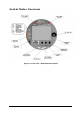
Socket Meter Overview Figure 1: Front view - Nameplate description Chapter 1 Introduction 3
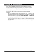
Chapter 2 Installation The eXpertmeter™ EM920 Socket meter is designed to mount into a standard meter socket. Follow the Installation summary below, to ensure that the unit is installed securely. The EM920 series can be mounted outside or in an enclosed and protected environment, such as in a switchgear cabinet. You may install a switch or circuit breaker nearby and label it clearly as the monitor’s disconnecting mechanism.
Mechanical Installation Refer to the figures provided in this section to properly perform the mechanical installation.
Physical Description Device Structure Figure 3: EM920 internal structure Optional Modules location Figure 4: EM920 internal structure 6 Chapter
Meter External connections Figure 5:Meter Base – rear view Chapter 2 Installation 7
Electrical Installation Before installing, ensure that all incoming power sources are shut OFF. Failure to observe this practice can result in serious or even fatal injury and damage to equipment. Voltage Inputs There are 3 AC Y-connected voltage inputs of 207VAC (phase-to-phase) and neutral, via socket meter blades. The EM920 Power Supply Inputs are the same as the Voltages Inputs Current Inputs There are 4 current inputs up to 50A, connected to external CT’s via socket meter blades.
Figure 7: Four Wire WYE Connection No PTs Using 3CTs - Wiring Setup: 4Ln3 Figure 8:Four Wire WYE Connection Using 3 PTs and 3(4) CTs - Wiring Setup: 4Ln3 Chapter 2 Installation 9
Figure 9: Four Wire DELTA Connection Using no PTs and 3(4) CTs - Wiring Setup: 4LL3 Figure 10: Four Wire DELTA Connection Using 3 PTs and 3 CTs - Wiring Setup: 4LL3 10 Chapter
Figure 11: Three Wire DELTA Connection Using no PTs and 2 CTs - Wiring Setup: 3OP3 Figure 12: Three Wire DELTA Connection Using 2 PTs and 2 CTs - Wiring Setup: 3OP3 Chapter 2 Installation 11
Input / Output ports options Before I/O Module installation ensure that all incoming power sources are shut OFF. Failure to observe this practice can result in serious or even fatal injury and damage to equipment. On board I/O ports LOGIC/DISPLAY The EM920 LOGIC/DISPLAY board is equipped with two fast Dry contact detector – Digital Inputs 2DI unit, providing wet contact voltage of 24VDC, RS-485 communication port COM3 and USB device port.
Optional I/O modules 8DI The 8DI module consists of eight status inputs detection.
Relay Outputs (6RO – optional module) The 6RO module consists of: four FORM C (SSR) and two FORM A (EMR) relay outputs.
Figure 18: 4AO Connection It is recommended to connect unused Analog output channels to Common terminal. The 4AO module TERMINAL is for use only with equipment which has no live parts which are ACCESSIBLE The RATING of the insulation of the external equipment for use with the 4AO module, shall comply according to Installation Category III for insulation to be suitable for SINGLE FAULT CONDITION ⇒ • The external equipment TERMINAL connection type is normally terminal block for wire size 14 AWG (up to 1.
Communications options The EM920 has several communication alternatives depending on your ordering preferences. All communications ports, of different type, can be used simultaneously. The basic EM920 is equipped with one standard optical communication port (COM1), an optically isolated RS-485 communication port (COM3) and an USB Device Type A. Other COM ports are available as optional module.
USB Communication port (USB – on board) The EM920 provides a standard full speed USB DEVICE port. The USB DEVICE port connection is provided by the LOGIC/DISPLAY cable terminated with a standard USB type A connector as shown in figure 19 Figure 21: USB connection Optional Communication ports Wireless Communication port – GSM/GPRS module (COM2 – optional module) The Wireless Communication port – COM2 is provided by optional module: GSM/GPRS module.
To install the GSM/GPRS module follow instructions: 1) Remove the plastic cover 2) Remove the body shield 3) Plug-in the module in the COM slot and attach it to bracket using the two screws 4) Connect the GSM/GPRS antenna cable expander and pass it through the device base window cables 5) Mount back the body shield 6) Mount back the plastic cover The GSM/GPRS module is factory or Meter Shop plugged-in at the COM slot 1) Apply power to the meter 2) After one minute the "LNK" GREEN LED is flashing until it li
Figure 23: ETHERNET module RS-485/232 Communication port (COM4 – ETH optional module) The RS-485/232 Communication port – COM4 is provided by ETH optional module.
RS-232 mode In the RS-232 mode, the 485/232 wire must be tied to GND wire as shown in figure 25 Figure 25: Serial Communication Connection – RS-232 COM4 IRIG-B 1-ms satellite-synchronized clock from a GPS satellite clock that has an IRIG-B time code output connected to the IRIG-B input port. Connect the GPS receiver IRIG-B output to the IRIG-B/GND wires respectively. ETHERNET Communication port (ETH – optional module) The 10/100Base T Ethernet port – ETH is provided by optional module: ETHERNET module.
Auxiliary Power Supply AC/DC Auxiliary Power Supply The EM920 can be equipped with additional power supply to redundant the built-in power supply (Auxiliary Power Supply – APS).
Chapter 3 Communications 1.
Chapter 4 Replacing the Battery When the battery level drops below the minimum allowed threshold, the LCD graphic display, on the front of the device, shows: , indicating that the battery should be replaced.
Appendix: Technical Specifications Inputs Ratings AC Voltage inputs Va, Vb, Vc and Vref - 50/60Hz Reference voltage Un 57.73V up to 120V L-N (via PT) High input impedance = 10MΩ Voltage rating: 57.73 up to 120 Volts (L-N), 100 to 207 Volts (L-L) Voltage range 0 -144 V r.m.s, Crest factor >2 [VL-N x 1.2 x 2] peak up 288V (for PQ) Maximum Line to Line voltage 500 V r.m.s Temporary over voltage between live conductors and earth 240 V r.m.s Transient over voltage between live 1.
Power Supply Power supply Supplied from Monitored Voltage inputs Low Voltage Three Phase PS, Rated Inputs 50/60 Hz 57.73 – 120V AC ± 20% Insulation Dielectric withstand 2500V AC @ 1mn Operating Temperature range -40ºC to + 75ºC Output voltage +12V DC ± 5% Burden per phase (w/o AUX. PS) 6VA Burden per phase (w. AUX. PS) <0.
6RO Optional module3 Analog Outputs 4AO SSR – 4 relays (FORM C) 0.15A @ 250V AC/DC Operation time 1 ms Release time 1 ms Insulation Dielectric withstand 2500V AC @ 1mn EMR – 2 relays (FORM A), ½ cycle operation 5A @ 250V AC Operation time 5-7 ms + ½ cycle Release time 5-7 ms + ½ cycle Insulation resistance of open contacts > 2 MΩ or 1000V @ 1mn Insulation Dielectric withstand 2500V AC @ 1mn Terminals for wires size 16 x 2.
Communication ports COM1 Built-in Infra Red communication port DISPLAY unit IR port RS232 communication, TTL level, max baud rate 19.2 kb/s Protocols MODBUS RTU/ASCII and DNP3.0 Optically isolated 2500V AC @ 1mn Optical port per ANSI C12.18 Type 2 Basic COM2 Plug-in modules isolated communication port GSM/GPRS 4 Optional module RS232 communication, TTL level, max baud rate 115.2 kb/s GSM/GPRS module Quad Band GPRS class10 Protocols MODBUS/TCP or DNP3.
IRIG-B ETH-TX Protocols MODBUS RTU/ASCII and DNP3.0 USB connector Cable terminated with USB type A Input Isolation 2500V AC @ 1mn Time code signal Demodulated (pulse-width coded) Signal Level Unbalanced 5V Terminals for wires size 2 x 2.
Standards Compliance EMC Immunity ANSI C12.1 Reference: IEC 61000 Surge – IEEE C62.41.2-2002 100kHz ring wave 6kV / 0.5kA 1.2/50 µs – 8/20 µs 6kV / 3kA Magnetic field – ANSI C12.1 FTB – IEC 61000-4-4, level 4 4kV – measuring inputs 2kV – I/O and com. SWC – IEEE C37.90.1 Emission Safety Environment 2.5kV – measuring inputs, I/O an com. Electromagnetic RF Fields – ANSI C12.1 20V/m @ 200kHz – 10GHz ESD - IEC61000-4-2 15KV/– air/contact Radiated / Conducted - FCC/CFR 47 p.15 Class B ANSI C12.
Measurement Specifications Parameter Full Scale @ Input Range Voltage V1-V3 (L-n) 120 x PT ratio @ 120V Voltage V4 (calculated) 120V x PT ratio @ 120V Voltage V1-V3 (L-n) 69 x PT ratio Voltage V4 (calculated) 69 x PT ratio Line current I1- I4 CT primary current Fault current I1- I4 Active power Accuracy % % Reading FS Range Conditions ±0.0 5 1% up to 140% ±0.5 5% up to 140% ±0.0 5 1% up to 140% ±0.5 5% up to 140% ±0.06 ±0.
CT - primary current rating of external current transformer FSV - voltage full scale FSI - current full scale Vf - fundamental voltage If - fundamental current NOTES 1. Accuracy is expressed as ± (percentage of reading + percentage of full scale) ± 1 digit. This does not include inaccuracies introduced by the user's potential and current transformers. Accuracy calculated at 1second average. 2.