GDAŃSK integra_u_en 08/10 Firmware version 1.
WARNING In order to avoid any operational problems with the control panel, it is recommended that you become familiar with this manual before you start using the equipment. Making any construction changes or unauthorized repairs is prohibited. This applies, in particular, to modification of assemblies and components. Maintenance and/or repair operations should be performed by authorized personnel (i.e. the installer or factory service).
INTEGRA SATEL 1 New features in firmware versions 1.07 and 1.08 System operation The new INT-CR proximity card arm/disarm device enables arming / disarming and alarm clearing in many partitions by means of proximity cards, keyfobs and other passive transponders. Users The installer can define a minimum length of codes used in the system. New right: ZONE ISOLATION. Data entering A new, more intuitive way of entering hexadecimal values and names.
2 User Manual INTEGRA CONTENTS 1. 2. 3. 4. 5. GENERAL ............................................................................................................................4 ABOUT THIS MANUAL ............................................................................................................4 TECHNICAL RELIABILITY OF THE ALARM SYSTEM......................................................................4 ALARM SYSTEM OPERATING COSTS ..........................................................
INTEGRA SATEL 3 6.10 SYSTEM ARMED MODE ................................................................................................................ 34 6.11 ALARMS ..................................................................................................................................... 37 6.12 ALARM MESSAGING BY TELEPHONE ............................................................................................. 37 6.13 ANSWERING PHONE CALLS ...............................................
4 User Manual INTEGRA 1. GENERAL Thank you for choosing the product offered by the SATEL Company. High quality, large number of functions and simple operation are the main advantages of our alarm control panel. Wishing you full satisfaction with the choice you made, we are always ready to provide you with professional assistance and information on our products. Please note that, besides the control panels, SATEL manufactures many other components of alarm systems.
INTEGRA SATEL 5 It is necessary to periodically carry out a functional test of the alarm system. Check that the control panel responds to violation of individual detectors, that their fields of view are not masked, that there is a reaction to opening protected windows, and that sirens and telephone messaging work normally. Detailed instructions on the system testing should be provided by the installer.
6 User Manual INTEGRA • answering phone calls (this function is protected with a separate code) which allow to: − inform the user on the system status, − control via telephone some of the control panel functions, which were programmed by the service, • real-time printout of information regarding all or selected events that have occurred in the alarm system with the use of an external printer, • control of access to the facilities through doors provided with electromagnetic locks, • monitoring individual
INTEGRA SATEL 7 card arm/disarm devices, partition keypads, code locks, as well as proximity card / DALLAS chip readers. The LCD keypads and proximity card arm/disarm devices INT-CR may be used to control many partitions in various objects. The partition keypads control just one partition. Individual control devices are assigned by the installer to specified partitions. The users may operate the control panel only if they have access to partitions operated by particular keypads.
8 User Manual INTEGRA In case of the LCD keypad, the partitions indicated by the installer will be armed. In case of the partition keypad, the partition to which the keypad is assigned will be armed. The types of armed mode are described in section SYSTEM ARMED MODE. Press and hold down simultaneously the S and T keys for approx. 40 seconds to restart the keypad and display the information about keypad and control panel firmware version. 6.
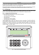
INTEGRA SATEL Fig. 2. View of INT-KLCDS-GR keypad. Fig. 3. View of INT-KLCDK-GR keypad.
10 User Manual INTEGRA Display The keypads are provided with a 2x16 character display with backlighting. The backlighting mode is determined by the installer. In the standby mode, the display shows the current date and time, it can also permanently show the keypad name. The format of displayed information is defined by the installer. The lower display line can be used to show the current status of selected partitions (up to 16), the displayed symbols being as described in the TESTS function.
INTEGRA - SATEL 11 GROUP (two green LEDs) – used in graphic mode functions to indicate which data set is currently displayed. The LEDs can show the number of zones or outputs, or indicate the corresponding expander bus. (See: section SELECTION FROM THE MULTIPLE-CHOICE LIST IN THE GRAPHIC MODE).
12 User Manual INTEGRA • Auto arming delay countdown (timer-controlled partitions) – a series of 7 sounds (of diminishing length). • Chime in LCD keypad – five short beeps – this is a response to activation of some detectors when the zone is disarmed. 6.1.3 Using LCD keypad Operation of the system from LCD keypad starts with entering the user CODE and pressing the key marked [#], [ok] or [*].
INTEGRA 6 7 8 9 0 SATEL 13 51 Selected events 52 All events Set time Troubles Outputs control Service mode Downloading 01 Start DWNL-RS 02 Finish DWNL-RS 03 Start DWNL-MOD. 04 Start DWNL-TEL 05 Start DWNL-CSD [only INTEGRA 128-WRL] 06 Start DWNL-GPRS [only INTEGRA 128-WRL] 07 ETHM-1 – DloadX 08 ETHM-1 – GuardX Note: The shortcuts in the DOWNLOADING menu are available when the control panel configuration and settings make it possible to use the selected function.
14 User Manual INTEGRA installer so that pressing the key [1] will be required). The [*] key enables exiting the function without saving the changes (which can result in quitting the user menu). Selection from the single-choice list Shown in the upper line of display is description of the function, and in the lower one – the currently selected item. You can scroll through the list of items, using the direction keys: T (down) and S (up). The X and W keys are not used.
INTEGRA Key 1 2 3 4 5 6 7 8 9 0 SATEL ! a d g j m p t w ? b e h k n q u x . ' c f i l o r v y , ` 2 3 4 5 6 s 15 Characters available after next keystroke " { } $ % & @ \ ^ | # 1 ] 0 7 8 z : 9 ; + - / = _ < > ( ) [ Table 1. Characters available when entering names. The lower case letters are available under the same keys (to change the letter case, press T key).
16 User Manual INTEGRA 4. 5. 6. 7. 8. as code Ç – performs function assigned to the arrow key (p. 46) as code Å – performs function assigned to the arrow key as code Æ – performs function assigned to the arrow key as code È – performs function assigned to the arrow key open door (entry) – controls the electromagnetic door lock (generates a USER ACCESS event) 9. open door (exit) – controls the electromagnetic door lock (generates a USER EXIT event) 10. 2 long sounds – signals reading of the card code 11.
INTEGRA SATEL 17 SATEL offers the following partition keypads for INTEGRA control panels: − INT-S-GR/INT-S-BL − INT-SK-GR These keypads differ by size and shape. The keypads are available with green or blue backlighting of the keys. Designation of the models with green display ends with "GR" letters, and that of the models with blue display – with "BL" letters. The backlighting may be permanent or time-controlled (switched on automatically). Fig. 5. INT-SK-GR partition keypad.
18 User Manual INTEGRA When all the LEDs are alternately blinking (from top to bottom), there is no communication between the keypad and the control panel. This situation may occur when the STARTER program is running in the control panel or the cable connecting the partition keypad to the control panel is damaged. It is possible to program the partition to be armed or disarmed after entering two codes PROG.
INTEGRA SATEL 19 Functions accessible from the keypad include: [CODE][#] arming and disarming of partition; alarm clearing; and/or execution of control function, [CODE][*] control of module on-board relay (e.g. electromagnetic door lock opening) can also be used for disarming (if the partition was armed, and the relay will not be activated for the armed mode time) PROG.
20 User Manual INTEGRA 4. change of the code has been blocked because another user "hit" this code at an attempt to change his own code. If the function of prompting about the necessity to change the code is activated, each use of such a "hit" code will be signaled with three double beeps.
INTEGRA SATEL 21 6.3.2 Operation in partition keypad mode with proximity card reader (INT-SCR) The device executes functions of the partition keypad, however it allows the users not only to use the access code, but the proximity card as well. Presenting the card is read out in much the same way as entering the access code and confirming it by the key. Holding the card (for approx. 3s) is recognized as entering the access code and confirming it by the key. Note: Entering an invalid access code (i.e.
22 – hold down the User Manual INTEGRA key for about 3 seconds – AUX (medical) alarm; – hold down the key for about 3 seconds – PANIC alarm. Another function of the keypad is the option to change the access code by the user PROG. In order to change the user code, do the following: 1. Press and hold down the key for about 3 seconds (LEDs designated [ALARM and ARMED] will start blinking alternately – red and green). 2.
INTEGRA SATEL 23 The audible signaling may be replaced by blinking of the keys backlight PROG. The beeps will translate, respectively, into keypad backlight extinguishments – if the backlight is ON, or into keypad backlight going on - if it is normally OFF. The keypad can also signal other situations, as selected by the installer (see section PARTITION KEYPADS). 6.3.3 Operation in entry keypad mode (INT-ENT) The main task of the entry keypad is to unblock the delay for zones with reaction time 3.
24 User Manual INTEGRA The keypad can also audibly signal the DELAY ACTIVATION TIME PROG. 6.4 CODE LOCKS SATEL offers the following code locks for the INTEGRA control panels: − INT-SZ-GR / INT-SZ-BL − INT-SZK-GR They differ by their size and shape. The code locks are available with green or blue backlighting. Designation of the models with green backlighting ends with "GR" letters, while that of the models with blue backlighting – with "BL" letters.
INTEGRA SATEL 25 Fig. 8. Code lock type INT-SZK-GR. The basic function of the code lock is to control access to the room where the door provided with electric catch, bolt or electromagnetic interlock is installed. The lock may also be used for partition control during a guard round in the facility. In order to open the door, enter the user CODE from the lock keypad and press [#] or [*]. The user must be authorized to use the particular code lock.
26 User Manual INTEGRA 6.5 PROXIMITY CARD AND DALLAS CHIP READER Using the card/chips activates control in the partition the reader is assigned to - in much the same way as entering this type of code from a partition keypad. Presenting the card to the reader/touching the reader with the chip is recognized by the reader in much the same way as entering the code and confirming it by the [*] key in the partition keypad. Holding the card/chip (for approx.
INTEGRA SATEL 27 • The service can add, edit and delete the object users, provided that the SERVICE CAN EDIT option has been enabled by the master user (administrator). • Each user of the system (except for the master) can have a telephone code assigned to him – see section ANSWERING PHONE CALLS. • Service code is rejected by the control panel when the service access is disabled. The rules of the service access to the alarm system are defined by the administrator.
28 User Manual INTEGRA − DURESS – used in an emergency situation, when the user has been forced to enter the code. Using the code will trigger a silent alarm. By default, the DURESS prefix consists of a suitable number of digits 4 (e.g. if the determined prefix length is 3, the default prefix is 444). For security reasons, it is useful to periodically change the prefixes. The master user of the object is authorized to change the prefixes and define the change RECALL TIME (see function ÆCHANGE PREFIX).
INTEGRA SATEL 29 3. Click with your mouse pointer on the CARD / DALLAS button. The card/chip adding window will open. 4. Select the method of adding the card/chip: by reading in on the reader, or by entering the number manually. 5. Depending on the selected method of adding the card/chip, select the reader (device with a reader) and read in the card/chip or enter its number twice. 6. Click with your mouse pointer on the ADD button. A window will open where you are supposed to enter the access code. 7.
30 User Manual INTEGRA zone will be violated as long as the keyfob button is depressed) and a corresponding reaction of the control panel. A button/combination of buttons can control one zone in the system. Zones are assigned to buttons/combinations of buttons individually for each user. On pressing any keyfob button (which does not have to control a system zone), information on the status of three selected system outputs will be presented for a few seconds on the keyfob LEDs.
INTEGRA SATEL 31 Reading the serial number during transmission 1. Select from the list the device which is to receive the transmission containing serial number (depending on configuration, this can be mainboard of INTEGRA 128-WRL control panel or ACU-100 controller). 2. Following the prompts displayed on the keypad, press the keyfob button twice, and after the message KEYFOB READ appears press the [#] key. 6.9.
32 User Manual INTEGRA 6.9.3 Removing keyfob by means of LCD keypad 1. Start the REMOVE ABAX KEYFOB function ([service code][*] ÆMASTERS ÆNEW MASTER/EDIT MASTER ÆREM.ABAX KEYFOB or [code][*] ÆUSERS ÆNEW USER/EDIT USER ÆREM.ABAX KEYFOB). 2. When the keyfob number is displayed, press the key [1]. 6.9.4 Removing keyfob by means of DLOADX program Removal of the keyfobs is possible by using the ABAX KEYFOBS window, after the keyfob data have been read (see section: ADDING KEYFOB BY MEANS OF DLOADX PROGRAM).
INTEGRA SATEL 33 1. Click at the selected user in the column corresponding to the button/combination of buttons to which you want to assign the zone. 2. Using the keyboard, enter the number of zone which is to be controlled by the button, and confirm by pressing ENTER. Part of the field in which the zone number is displayed will change its color to pink. After the data are saved into the ABAX system, which completes the procedure, the field background will change its color to white. 6.9.
34 User Manual INTEGRA 6.9.10 Configuring event generation rules by means of DLOADX program Enabling/disabling generation of events for particular keyfob buttons is possible by using the ABAX KEYFOBS window, after the keyfob data have been read (see section ADDING KEYFOB BY MEANS OF DLOADX PROGRAM). 1. Click at the selected user in the column corresponding to the button/combination of buttons for which you want to enable/disable the generation of events. 2.
INTEGRA SATEL 35 which prevented arming has been in the meantime removed, the partition will be armed. Otherwise, the list of causes which prevent arming will be displayed again. • If the SERVICE MESSAGE AFTER TAMPER ALARM and DO NOT ARM IF TAMPERED options are enabled by the installer, the arming will only be possible after repairing the tamper and clearing the message by using the service code.
36 User Manual INTEGRA 2. Call the ARMING MODE function. 3. Using the S and T keys select one of the suggested arming modes and press [#]. 4. Call the ARM function and select (highlight) the partition to be armed. 5. Press the [#] key. In order to re-enable the special armed mode, the above procedure must be repeated.
INTEGRA SATEL 37 Note: The special armed modes, as described earlier, are also defined for timers. • partition arming control by means of a special zone programmed (by the installer) as arming control zone. In practice, it may be a mechanical switch; key switch, pushbutton, radio switch. It is also possible to control such a zone by means of the REMOTE SWITCH type output (see: ANSWERING PHONE CALL).
38 User Manual INTEGRA messages into SMS messages, thus allowing the use of this form of notifying also in the other INTEGRA control panels. The number of telephones to which the messaging is effected, and the number of available voice messages or text messages, depends on the control panel size. In case of notifying by a voice message, the control panel settings may require confirmation (acknowledgement) that the message has been listened to.
INTEGRA • • • • • • • SATEL 39 Two long beeps follow receipt of an incorrect code. If the entered code is invalid, the control panel will signal it by two long beeps and will not be answering any calls for the next 4 minutes. The control panel is in partition status information mode. It waits for user’s response for 15 seconds, generating one short beep every two seconds. You are expected to enter the partition number from the telephone keypad (in two-digit format, e.g., 01; 05; 12; 25).
40 User Manual INTEGRA • The control panel is protected against any attempts to scan the code – after three consecutive attempts to get access to the panel using wrong codes within one telephone communication session, the function of answering the modem signals will be disabled for 30 minutes. 6.15 SMS CONTROL ONLY INTEGRA 128-WRL The INTEGRA 128-WRL control panel makes available to the users the function of control by SMS messages.
INTEGRA SATEL Defer auto-arm postpone the auto-arming Set auto-arm d.
42 User Manual New prox. card add proximity card Rem. prox. card remove proximity card New DALLAS add DALLAS chip Remove DALLAS remove DALLAS chip New RX keyfob add keyfob supported by INT-RX module Rem.
INTEGRA Erase s.message Tests Partitions Zones Supply voltage Radio devices Zones test New Burglary zones Fire/tech.zones View results Finish test Clear results Battery test Manual tr. test Station 1A test Station 1B test Station 2A test Station 2B test Messaging test Answering test Prox. card test View masters Keypad name File in DloadX Panel version ST prog.version GSM IMEI/v/sig. IP/MAC ETHM-1 Modules version Time synchron.
44 User Manual INTEGRA View cleared alarms The function is available, provided that the user has not viewed the violated zones. It makes it possible to check which zones triggered the alarm. After completion of the viewing, the function will be unavailable. System reset The function is available to the installer (service), if the option REQUIRED SYSTEM RESET AFTER VERIFIED ALARM is enabled, and a verified alarm took place.
INTEGRA SATEL 45 Disarm (2codes) The function is available when at least one partition in the system requires entering two codes to be disarmed. After starting the function, select the partition(s) to be disarmed ( partition selected; - partition not selected) and confirm using the [#] key. Depending on how the partition has been configured by the installer, it may also be necessary to determine the code validity period. If the code validity time is not programmed by the user, it will be 60 seconds.
46 User Manual INTEGRA Arming mode This function makes it possible to select a special mode of arming, which will allow the user to stay in the facility. The following armed modes are available: • Full (default) • Full + bypasses • Stay • Stay, delay = 0 (off) The special armed modes are discussed in section SYSTEM ARMED MODE, page 35. After selection of the arming mode, the control panel returns to the user function menu, thus enabling the selected partitions to be armed.
INTEGRA SATEL 47 Change prefix The function is available to the master, if the installer has allowed prefixes to be used in the system. The installer, using the corresponding service function (ÆSERVICE MODE ÆOPTIONS ÆPREFIX LENGTH), can determine the prefix length (1–8 digits). If the prefix length programmed by the installer is 0, no prefixes will be used. The CHANGE PREFIX function enables programming the prefixes and the time to remind of the need to change the prefix.
48 User Manual INTEGRA 4. Time not renewable – code, for which the validity time period is limited to the number of days specified when entering a new user. After this user code type is chosen (when entering or editing), the EXISTENCE TIME function appears in the menu, where the number of code validity days should be defined. The code validity period may be changed by the user who entered a new user, or by the master user. 5.
INTEGRA SATEL 49 It is possible to plan the guard rounds only for one of the above situations (for example, when the partition is armed). Missing guard round will generate the “No guard" event which may be signaled at one of control panel outputs. 11. Schematic – code allowing the user to get access to the system according to a time scheme. One of the eight time schemes as may be defined by the installer should be assigned to such a code. The access scheme is based on 64 system timers.
50 User Manual INTEGRA • The installer may define a list of rights to be instantly assigned to the new user. The other rights, available but not included in the list, will have to be assigned individually by the person entering the new user. Keypads – assignment of proximity card arm/disarm devices, partition keypads, code locks, and expanders of proximity cards/DALLAS chips readers which the user will be authorized to use.
INTEGRA SATEL 51 inhibited (or unbypassed) will be displayed. Use the S and T keys to scroll through the list. Shown in the top right corner of the display is an additional symbol: – zone is not bypassed; – zone is inhibited; – zone is isolated. Pressing any number key will change the displayed symbol to one of the following ones: – the zone is to be inhibited; – the zone is to be unbypassed. Press the X or W key to switch the keypad over to graphic mode.
52 User Manual INTEGRA Events The function makes possible to scroll the list of events stored in the control panel memory. The events are given in the sequence order of their occurrence. The S key permits going back to the previous event, while the T key – to the next one. If none of these keys is depressed for a few seconds, names related to the particular event will appear on the display, shown alternately with the event description.
INTEGRA SATEL 53 Selection of partitions influences the contents of the list displayed when viewing event types from 1 to 4 (event type numbers according to the list given below). List of event types: 1. Zone & tamp.al. - alarms for zones, tamper alarms. 2. Other alarms - other alarms. fire, auxiliary, technical alarms, no guard round. 3. Arm/Disarm/Clr - arming and disarming, alarm clearing. 4. Zone bypasses - bypassing/unbypassing zones. 5.
54 User Manual INTEGRA For the timer to operate it is necessary to: 1. Start the ACTIVE function and enable it ( ). 2. Select operation mode: everyday or weekly. 3. Set the timer on and/or off time. • In case of the daily cycle timer, after selecting the mode, the "Every day timer turned on: HH:MM" text will appear on the display. Enter the hour (HH) and minute (MM) of switching the timer on. Press S or T to enter hour and minutes of switching the timer off.
INTEGRA SATEL 55 GuardX IP – the function enables programming the address of the computer, on which the GUARDX program is installed. The address must be set if the control panel is to initiate communication with the GUARDX program through Ethernet, using the TCP/IP protocols (see: description of the ETHM-1 – GUARDX function, available in the DOWNLOADING submenu). It can be entered as a name or IP address.
56 User Manual INTEGRA – zone tamper, – zone violation, s – tamper alarm memory, a – alarm memory, – zone OK. Supply voltages – the function enabling power supply voltage level to be checked for individual expanders. The display shows the expander name and approximate power supply voltage level for the given expander. Radio devices – the function makes it possible to check the radio signal level in the ABAX wireless system devices working in conjunction with the control panel.
INTEGRA SATEL 57 Keypad name – the function shows on display the name of particular keypad (default or installer assigned). File in DLOADX – the function displays the date and time of writing the computer data (DLOADX program) to the control panel, as well as the name of data file. Panel version – the function shows the current control panel firmware version number on the keypad display.
58 User Manual INTEGRA The function can be started from LCD keypad, without entering of any code, by pressing successively the [8] and [#] keys PROG. Starting the function by the user will display a list of output groups. You can scroll the by means of the S and T keys. After selecting one of the output groups and pressing the [#] or X key, a list of controllable outputs will be displayed. Press the W key to return to the group list.
INTEGRA SATEL 59 SHUTTER UP. The current status of the outputs is indicated on the display next to the output name in the following way: - outputs inactive (off), Ç - SHUTTER UP output active (on), È - SHUTTER DOWN output active (on). Only one of the outputs can be activated at a time. After pressing the [#] or X key, a line mark appears under the field, in which the output status is displayed.
60 User Manual INTEGRA 8. CONFORMANCE TO CLC/TS 50131-3 REQUIREMENTS If the control panel has been configured in accordance with the requirements of CLC/TS 50131-3: • the maximum number of events generated by a single source is 3; • at least 6-digit codes must be used, to make minimum 100 000 codes available to every system user.
INTEGRA SATEL 9. APPENDIX A List of messages displayed in keypad when viewing the troubles: OUT[n] trouble: [n] =1–4 – number of control panel output AUX trouble Keypad supply trouble Expander supply trouble System battery trouble System AC (230V) trouble Data bus DT1 trouble Data bus DT2 trouble Keypad data bus DTM trouble System real-time clock trouble No DTR signal on RS printer port No system battery Modem initialization error Modem answers ERROR on AT...
62 Long viol. z.[n]: No violat. z.[n]: No AC exp.[n]: Batt.trb.exp.[n]: No bat. exp.[n]: Exp.[n] restart: No expander [n]: Changed exp.[n]: Exp. [n] tamper: BUSY sig.exp[n]: Reader A exp.[n]: Reader B exp.[n]: Overload exp.[n]: BUS shrt.exp.[n]: Jam of r.exp.[n]: Low batt. z.[n]: No radio z.[n]: No rad. out.[n]: Zn. bypass [n]: Zn. [n] tamper: viol. of zone [n]: V.zn. trbl. [n]: Low batt.u.
INTEGRA SATEL 63 10. APPENDIX B EXPLANATION OF SOME TECHNICAL TERMS All definitions apply to the alarm system based on the INTEGRA control panel. STARTER The program activated in the control panel after power-up to check integrity of the basic program stored in FLASH memory and to enable a new control panel firmware version to be loaded into this memory. FLASH memory The memory, where the control panel basic program is stored.
64 User Manual INTEGRA 11. APPENDIX C This appendix contains typical descriptions of the operations to be carried out when calling some user functions. Since the user function menu depends on programming by the installer and particular user authority level, the following keypad displayed texts may look different in practice and are shown here for reference only. Example 1: ARMING (part I: [CODE][#]) - partition No. 2 named “Book-keeping", belonging to Object 1; user – the master user.
INTEGRA SATEL 65 • using partition numbers – in the graphic mode described below. This is the mode for the user who exactly knows the numbers of partitions in the alarm system, or the user, who wants to quickly check how many partitions are not armed yet. X W Keys enabling the cursor to be moved in the graphic mode. S T Keys enabling the keypad to be toggled between the text mode and the graphic mode. The X [3] symbol denotes partitions, which may be armed (1, 2, 3 and 4).
66 Note: T X or [#] User Manual INTEGRA If only one partition is armed, it will be disarmed immediately after pressing the [#] key (and the end message will be displayed). If an alarm is signaled for the partition, it may be cleared together with disarming. Move down the arrow indicating the function that can be started. Start the Disarm selected function. What to disarm: Workroom 1 S or T Scroll through the list with partition names.
INTEGRA SATEL 67 Notes: • One-time bypassing (inhibiting) of the a.m. zones will be possible if they belong to partitions, which is not armed. • Permanent bypassing (isolating) of the zones can be performed in much the same way, however the ISOLATE function must be selected instead of the INHIBIT function. [3][8][4][0][7][*] Enter code – calling the user function menu. Á T or S Arm Change own code Scroll through the list with accessible function names.
68 [*] User Manual Return to the Zone bypasses submenu. Á [*] INTEGRA Inhibit Isolate Exit the user function menu. Note: Zone bypass (inhibit) is cancelled after disarming of the partition to which the bypassed zones belong. Example 4: ZONE STATUS VIEWING - call function by holding down the key [1]. [1] Call the function of control panel zone status viewing. Hold down the key for approximately 3 seconds – information on the first 32 system zones will be displayed in the graphic mode.
INTEGRA SATEL 12. BRIEF DESCRIPTION OF OPERATING THE SYSTEM FROM KEYPAD blinking – system trouble – use the TROUBLES user function to view the troubles lit – all partitions operated by the keypad are armed blinking – some partitions are armed ( - 1. group (numbers: 1-32) / 1. expander bus - 2. group (numbers: 33-64) / 2. expander bus - 3. group (numbers: 65-96) - 4.
70 User Manual INTEGRA 13. HISTORY OF THE MANUAL UPDATES Given below is a description of changes as compared with the manual for the control panel with firmware in version v1.00. FIRMWARE DATE INTRODUCED CHANGES VERSION 2005-09 1.03 2006-07 1.04 2007-08 1.05 • Supplemented information on the ETHM-1 module (p. 6, 57). • Added information on optional blocking of keypad (p. 12), partition keypad (p. 19) and code lock (p. 25) after three wrong codes are entered.
INTEGRA SATEL • • • • • • 2007-10 1.05 • • • • • • • 2008-06 1.06 • • • • • • • • • • • • • • • • 2009-08 1.06 1.07 • • • • • • • 71 of a timer (p. 37, 54). Supplemented the diagram showing user functions menu (p. 40). Added information on the option to assign keyfobs to the users (p. 50). Added information on the option to assign zones to keyfob buttons (p. 50). Added information on the option to terminate zones test before expiry of programmed time (p. 56).
72 2010-08 User Manual 1.07 1.08 INTEGRA • Information on "ETHM-1 – DloadX" and "ETHM-1 – GuardX" functions has been added in description of "Downloading" submenu (p. 59). • Some figures have been modified. • Information on INT-KSG keypad has been added. • Information on INT-CR proximity card arm/disarm device has been added. • Since the INT-KSG keypad has been added to SATEL's offer, section "LCD keypads" has been re-edited and modified (p. 8), and section "Using LCD keypad" (p.
SATEL sp. z o.o. ul. Schuberta 79 80-172 Gdańsk POLAND tel. + 48 58 320 94 00 info@satel.pl www.satel.