
User's Guide


ANNEX to SATELLINE-3AS User Guide
SATELLINE-3AS/TC
02.12.2004 (v.1.0)
Page 5 of 11
SATEL Oy, P.O.Box 142, FIN-24101 Salo, Finland
Street: Meriniitynkatu 17, FIN-24100 Salo, Finland
Tel: +358 2 777 7800, Fax: +358 2 777 7810, E-mail: info@satel.fi
www.satel.fi
1 INTRODUCTION
SATELLINE-3AS/TC is a member of the versatile SATELLINE-3AS radio modem family.
Consisting of a data modem and a UHF radio transceiver, it provides a wireless, transparent and
half-duplex serial data link with other similar radio modules or compatible SATELLINE radio
modems manufactured by SATEL Oy.
SATELLINE-3AS/TC is designed for integration into the terminal equipment. The component
blocks are shielded by metal plates, but the housing and the related mechanics are supplied by
the client. Also the EMC characteristics of the radio module are completed for the combined
equipment.
A number of new SL commands has been implemented to the modem controller software for full
control of the features of SATELLINE-3AS/TC in integrated use.
The implementation of SATELLINE-3AS/TC is based on the widely used SATELLINE-3AS radio
modem – the radio communication and the user interface are similar. The main differences to
SATELLINE-3AS are:
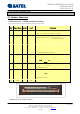
1. SATELLINE-3AS/TC is delivered without the housing – only the two PCBs (the logic board
and the RF board shielded as a one card) are supplied by SATEL
2. Antenna connector is a female MMCX connector.
3. The antenna circuitry of the radio module includes an additional filter on GPS frequencies
in order to avoid any interference to the GPS receivers.
4. The main header is a 32-pin Eurocard connector type B.
5. The operating voltage must be 6.5V…18VDC.
SATELLINE-3AS/TC has two pins in the header connector for controlling the external LED
indicators, the one for the external green LED and the other for the red LED. By different
combination of the LED status, the user of the application device can monitor the status of the
SATELLINE-3AS/TC radio module.