SATELLINE-4Pro User Guide v0.93 DRAFT IMPORTANT NOTICE All rights to this manual are owned solely by Satel Oy (referred to in this user guide as Satel). All rights reserved.
SATELLINE-4Pro User Guide v0.93 DRAFT RESTRICTIONS ON USE SATELLINE-4Pro radio modems have been designed to operate on frequency ranges, the exact use of which differs from one region and/or country to another. The user of a radio modem must take care that the said device is not operated without the permission of the local authorities on frequencies other than those specifically reserved and intended for use without a specific permit. The allowed max output power depends on the type of station.
SATELLINE-4Pro User Guide v0.93 DRAFT PRODUCT CONFORMITY Information coming soonest.
SATELLINE-4Pro User Guide v0.93 DRAFT WARRANTY AND SAFETY INSTRUCTIONS Read these safety instructions carefully before using the product: -Warranty will be void, if the product is used in any way that is in contradiction with the instructions given in this manual, or if the radio modem housing has been opened or tampered with. -The radio modem is only to be operated at frequencies allocated by local authorities, and without exceeding the given maximum allowed output power ratings.
SATELLINE-4Pro User Guide v0.93 DRAFT TABLE OF CONTENTS IMPORTANT NOTICE ......................................................................................... 1 RESTRICTIONS ON USE ..................................................................................... 2 PRODUCT CONFORMITY.................................................................................... 3 WARRANTY AND SAFETY INSTRUCTIONS ......................................................... 4 TABLE OF CONTENTS ......................
SATELLINE-4Pro User Guide v0.93 DRAFT 7.1 Transmitter ........................................................................................... 22 7.2 Receiver ................................................................................................ 23 7.3 Priority RX/TX ....................................................................................... 23 7.4 Forward Error Correction ..................................................................... 24 7.5 Error checking ..........
SATELLINE-4Pro User Guide v0.93 DRAFT 9.1.9 9.1.10 9.1.11 9.2 Restoring factory settings ........................................................................................... 46 Adjusting the contrast of the LCD-display .................................................................... 46 Saving modified values into the internal memory ......................................................... 47 Changing parameters using the SL-commands .................................. 47 9.2.1 9.2.2 9.2.3 9.
SATELLINE-4Pro User Guide v0.93 DRAFT 14.3 RF-cables .............................................................................................. 67 14.4 Antennas .............................................................................................. 68 14.5 Filters and lightning protectors ........................................................... 68 15 APPENDIX A ....................................................................................... 69 16 APPENDIX B ....................
SATELLINE-4Pro User Guide v0.93 DRAFT INTRODUCTION Satel Oy is a Finnish electronics and Telecommunications Company specialising in the design and manufacture of wireless data communication products. Satel designs, manufactures and sells radio modems intended for use in applications ranging from data transfer to alarm relay systems. End users of Satel products include both public organisations and private individuals. Satel Oy is the leading European manufacturer of radio modems.
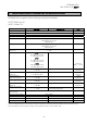
SATELLINE-4Pro User Guide v0.93 DRAFT 1 SATELLINE-4Pro TECHNICAL SPECIFICATIONS SATELLINE-4Pro complies with the following international standards: o FCC CFR47 part 90 o RSS-119 Issue 12 RECEIVER Frequency Range Tuning Range Channel Spacing Spurious Radiations Duty Cycle 35W *) Duty Cycle 10W *) Frequency Error Tolerance Sensitivity TRANSMITTER 406.180 ... 470 MHz 63.82 MHz 12.
SATELLINE-4Pro User Guide v0.93 DRAFT Timing Electrical Interface Interface Connector Data speed of I/O-interface Data speed of Radio Interface Data Formats Modulation DATA MODEM RS-232 RS-232 8-pin ODU 9600 – 115200 bps Up to 28800 bps (25 kHz channel) / Up to 14400 bps (12.5 kHz channel) Asynchronous RS-232 4FSK, 8FSK, 16FSK, GMSK (PacificCrest, TRIMTALK **) **) TRIMTALK is a trademark of Trimble Navigation Ltd.
SATELLINE-4Pro User Guide v0.93 DRAFT 1.
SATELLINE-4Pro User Guide v0.93 DRAFT 2 OTHER FEATURES SATELLINE-4Pro radio modem fulfils the IP67 (NEMA 6) standard. With an IP67 rating a product will be totally protected against dust and remain completely sealed when immersed in water to a depth between 15 cm and 1 meter. SATELLINE-4Pro modem is equipped with a high power 35 W transmitter. It is designed for easy mobile use in demanding field conditions.
SATELLINE-4Pro User Guide v0.93 DRAFT 3 SATELLINE-4Pro SPECIAL FEATURES 3.1 Call Sign SATELLINE-4Pro has a CALL SIGN identifier -feature required in some countries. A call sign can be formally assigned by a government agency, informally adopted by individuals or organizations, or even cryptographically encoded to disguise identity of a station. A call sign is an FCC (in US) or other regulatory authority assigned identifier that is issued along with the license for operating a radio modem.
SATELLINE-4Pro User Guide v0.93 DRAFT power goes to 2W, at 80°C to 10W, at 78°C to 20W, at 75°C to 25W and at 73°C the modem operates again at the full 35W carrier power. 3.3 Protection of current In case of a bad antenna impedance matching the current consumption of the Power Amplifier may be too high. For this reason the maximum current is limited to 12 A. If the current tends to increase over 12 A, the automatic power control decreases the power level until the current drops under 11.5 A.
SATELLINE-4Pro User Guide v0.93 DRAFT 4 SERIAL INTERFACE The radio modem is referred to as DCE (Data Communication Equipment) whereas the PC is referred to as DTE (Data Terminal Equipment). SATELLINE-4Pro includes a 8 pin ODU which contains all the connections required to establish communication between the radio modem, acting as the DCE, and the PC, acting as the DTE. All EMC-requirements set forth by authorities have been taken into account in the design of the radio modem.
SATELLINE-4Pro User Guide v0.93 DRAFT 5 USER INTERFACE 5.
SATELLINE-4Pro User Guide v0.93 DRAFT 5.2.1 SATELLINE-4Pro LCD-display after power-up The display shows the basic information which is revolving automatically in 5 seconds. Display in Data Transfer Mode (transmit/receive mode) Y -120 11.5V TX 430.000.000 RX 430.000.000 TX:35W SETUP 11.5V Compatibility: Satel 3AS TX:35W SETUP Y -120: Field strength of last received transmission or noise level. 11.5 = Supply voltage/battery level indicator. TX/RX = Operational TX and RX frequency.
SATELLINE-4Pro User Guide v0.93 DRAFT Display in Info mode. Pressing shows the next window. SATELLINE-4Pro S/N: FW:1.0.0.0 Exit Product name Serial number FW: Firmware version TX 430.000.000 RX 430.000.000 Ref 430.000.000 Exit TX frequency RX frequency Reference frequency Band 1 limits Lo 406.180.000 Hi 470.000.000 Exit The modem can be limited to operate only on certain frequencies. The range is shown as LO=Low and HI=High. Band 2 limits Lo 406.180.000 Hi 470.000.
SATELLINE-4Pro User Guide v0.93 DRAFT 6 CONNECTION INTERFACES NOTE! When installing the cables of the serial interface, it is recommended that the operating voltage of all devices is powered OFF. 6.1 RS-232 interface RS-232 standard defines the method of serial data transfer between a computer and its peripherals. The definition includes both the interface type and signal levels. Most computers and peripherals contain one or more RS-232 type serial ports.
SATELLINE-4Pro User Guide v0.
SATELLINE-4Pro User Guide v0.93 DRAFT 7 RF INTERFACE The SATELLINE-4Pro has a single TNC type RF-connector with impedance of 50 Ohm. When the modem is supplied the frequency is set to “default channel”. The user can change the frequency afterwards by 63.82 MHz. Of course, all local regulations set forth by the authorities must be taken into consideration. The data speed of the radio interface is set to “default speed”. It can also be set afterwards.
SATELLINE-4Pro User Guide v0.93 DRAFT 7.2 Receiver The sensitivity of the receiver depends on the channel spacing of the radio modem (=data speed of the radio interface) and on the mode of the FEC (error correction) according to the table below (BER 10E-3): 4FSK FEC OFF 4FSK FEC ON 8FSK FEC OFF 8FSK FEC ON 16FSK FEC ON 12.
SATELLINE-4Pro User Guide v0.93 DRAFT 7.4 Forward Error Correction Forward Error Correction, FEC-function is switched ON (or OFF) by using the Programming Mode. When activated, the FEC-function will cause the SATELLINE-4Pro to automatically add additional error correction information, which increases the amount of transmitted data by 30 %. It is used by the receiving radio modem to correct erroneous bits - as long as the ratio of correct and erroneous bits is reasonable.
SATELLINE-4Pro User Guide v0.93 DRAFT 7.7 User data whitening In some cases, if the user data includes a large number of constant characters, additional bit errors may appear. The use of error correction (FEC) is recommended in such cases. If that is not possible, the Data whitening feature can be used to improve the reliability of data transfer. NOTE! All radio modems, which are to communicate with each other, must have the same setting for Data whitening (ON or OFF).
SATELLINE-4Pro User Guide v0.93 DRAFT 7.8.2 Configuration by using SL commands “SL@S=” command selects the compatibility mode: ”SL@S=0” sets SATELLINE-3AS (default). ”SL@S=1” sets PCC-4FSK ”SL@S=2” sets PCC-GMSK ”SL@S=3” sets TRIMTALK GMSK, RX fitted to Pacific Crest transmitters “SL@S=4” sets TRIMTALK GMSK, RX fitted to Trimble transmitters “SL@S=5” sets PCC-FST The modem responds with “OK” message if the requested mode is supported or “ERROR” if the mode is not allowed.
SATELLINE-4Pro User Guide v0.
SATELLINE-4Pro User Guide v0.
SATELLINE-4Pro User Guide v0.93 DRAFT Note 2. If error correction is ON (FEC ON) and TRIMTALK mode is activated by using ”SL@S=3” command, the firmware automatically switches SATEL FEC OFF temporarily, and turns it back at the mode return. 7.8.5 Support for Local / Remote addresses If the modem has TX address ON then primary TX address is handled in the same way as Remote address in Pacific Crest PDL modems. The default value is 0x00FF (255 in decimal format) i.e. the broadcast address.
SATELLINE-4Pro User Guide v0.93 DRAFT 7.8.6.1 Transmission delays using Pacific Crest 4FSK on 25 kHz channel The table below presents the typical latency vs. the size of the message. The delays are measured from the end of transmitted data to the end of received data on the serial interface. Number of bytes sent Bps 1200 4800 9600 19200 38400 1 77 ms 48 ms 43 ms 40 ms 39 ms 10 159 ms 68 ms 52 ms 45 ms 41 ms 100 971 ms 317 ms 209 ms 154 ms 127 ms 500 4590 ms 1438 ms 912 ms 650 ms 519 ms 7.8.6.
SATELLINE-4Pro User Guide v0.93 DRAFT 8 TRANSPARENT DATA TRANSMISSION 8.1 Serial interface, data format The SATELLINE-4Pro serial interface uses an asynchronous data format. No external synchronising signal is needed, since necessary timing information is acquired from the start and stop bits transmitted before and after each data field bits (byte). The data transfer speed of the serial interfaces can be set to 9600, 19200, 38400, 57600 or 115200 bps (bits per second).
SATELLINE-4Pro User Guide v0.93 DRAFT Handshaking is not needed if the system protocol is designed to prevent collisions (data contention) by the use of polling, or if there is little traffic and also if there is no harm from occasional data contention situations (several radio modems try to transmit at the same time). 8.2.1 CTS-line The options for CTS-line are: 1) Clear To Send CTS is active when the radio modem is ready to accept data for new transmission.
SATELLINE-4Pro User Guide v0.93 DRAFT 8.3.1 Data buffering in the radio data modem Whenever the radio modem is in Data Transfer Mode it monitors both the radio channel and the serial interface. When the terminal device starts data transmission the radio modem switches to transmission mode. At the beginning of each transmission a synchronisation signal is transmitted and this signal is detected by another radio modem, which then switches into receive mode.
SATELLINE-4Pro User Guide v0.93 DRAFT The maximum absolute time is always 170 ms independent from the value of the Pause length given in the set-up. An increase in the Pause length increases the round trip delay of the radio link correspondingly; this is due to the fact that the radio channel is occupied for the time of the Pause length after each transmission (the time it takes to detect a pause). If this is not acceptable, the TX delay setting may also be useful in special cases. 8.3.
SATELLINE-4Pro User Guide v0.93 DRAFT Example of a long data blocks: 00 This is a long testline of SATELLINE-3AS radio modem The strength of the received signal can be monitored using the LCD-display of the receiving radio modem. NOTE 1! Green TD led indicates active test mode. NOTE 2! Normal data transfer is not available while the Test mode is active. Remember to switch it OFF before starting the normal data transfer. NOTE 3! Message Routing and FCS mode must be disabled prior to set ON the Test mode.
SATELLINE-4Pro User Guide v0.93 DRAFT 9 SETTINGS The configuration of SATELLINE-4Pro can be easily changed. Simply by connecting MODE pin (see chapter 6.2) of the data connector to ground (GND) the radio modem will switch into Programming Mode. Serial PORT 1 is used whenever the radio modem is in the Programming Mode. The serial port settings are 9600 bps, N, 8,1 (data transfer speed 9600 bps, none parity, character length 8 bits and one (1) stop bit).
SATELLINE-4Pro User Guide v0.93 DRAFT - RSSI value Y-102 (here -102 dBm) of the last received message or - current noise level e.g. n-115 Battery level respectively on the upper right corner. >Radio frequency Radio settings After pressing the ”SET-UP-button the Addressing display will show the main menu, which Port 1 is a list of modifiable parameters. Port 2 Pressing the ▲▼ buttons the cursor Handshaking moves upwards and downwards.
SATELLINE-4Pro User Guide v0.93 DRAFT Band 1 limits Lo 403.00000 MHz Hi 473.00000 MHz TX & RX freq selected The frequency Band 1limits will be shown. Press and to get the Band 2 limits. Press “Set” to activate the change frequency window. Cancel The cursor > will now blink under the first digit of the value indicating the (this first digit cannot be edited). To move onto the next digit, press ”Next”. ▼ Set New common freq 468.
SATELLINE-4Pro User Guide v0.93 DRAFT 9.1.2 CHECKING/CHANGING THE REFERENCE FREQUENCY >Radio frequency Radio settings Addressing Port 1 Press SETUP, set cursor at the Radio frequency and Port 2 press Select. Handshaking Additional Tests Factory setup Contrast EXIT▲▼Select Press ▲ or ▼ until the cursor points at “Reference freq” selection and press ”Change”. TX & RX freq TX freq RX freq > Reference freq Ch Spacing Back ▼ Change Band 1 limits are shown.
SATELLINE-4Pro User Guide v0.93 DRAFT 9.1.3 Changing radio settings (transmitter power and receiver sensitivity) Radio frequency >Radio settings Addressing Press ▲ or ▼ until Port 1 Port 2 the cursor > points Handshaking to “Radio settings” Additional selection and press ”Select” to move on Tests Factory setup to the submenu. LCD-Contrast Exit ▲ ▼ Select Press ▲ or ▼ until the cursor > points to the setting to be modified and press ”Change”. >TX level Sig.
SATELLINE-4Pro User Guide v0.93 DRAFT MODIFYING THE COMPATILBILITY: TX level Sig. Threshold TX start delay >Compatibility Press ▲ or ▼ until the cursor > points to the setting to be modified and press ”Change”. Back ▲▼ Change >SATELLINE-3AS PacCrest-4FSK PacCrest-GMSK TrimTalk450s(P) TrimTalk450s(T) PacCrest-FST The display will show the current value. Press ▲ or ▼ until the cursor > points to the desired value and press ”SET”. Cancel ▲ ▼ Set MODIFYING THE CALL SIGN: Sig.
SATELLINE-4Pro User Guide v0.93 DRAFT Select the desired submenu (RX or TX address) by pressing ▲ or ▼ and finally press ”Change”. >RX addr OFF TX addr OFF RX addr->RS OFF TX add auto OFF Back ▼ Change Press ▲ or ▼ until the first digit of the address has reached the desired value and move on to the next digit by pressing ”NEXT”. RX address >0000 0000 OFF ^ Cancel ▲▼ Next Repeat the above described eight (8) times.
SATELLINE-4Pro User Guide v0.93 DRAFT 9.1.5 Changing serial port settings (Port 1) NOTE! The radio modem has one serial port, PORT 1 which complies with the RS-232 standard. PORT 2 is not in use and the settings of serial PORT 2 cannot be changed. Radio frequency Radio settings Addressing Press ▲ or ▼ until the cursor > >Port 1 points to the desired port (in this Port 2 example to Port 1) and move on Handshaking Additional to the submenu by pressing Tests ”SELECT”.
SATELLINE-4Pro User Guide v0.93 DRAFT MODIFICATION OF THE NUMBER OF STOP BITS: Press ▲ or ▼ until the cursor > points to the desired number of STOP bits. Confirm selection by pressing ”SET”. The display will return to the previous (higher) level submenu. NOTE: The starting position of the cursor indicates the previously set value. >1 stop bit 2 stop bits Cancel ▲▼ Set 9.1.
SATELLINE-4Pro User Guide v0.93 DRAFT 9.1.7 Selecting special functions Press ▲ ▼ until the cursor > points to “Additional” selection and press ▼ ”SELECT” to move on to the submenu. Radio frequency Radio settings Addressing Port 1 Port 2 Handshaking >Additional Test Factory setup LCD-Contrast Exit ▲▼ Select Press ▲ or ▼ until the cursor > points to the setting to be modified. Press ”CHANGE” to toggle the status of the said parameter from ”ON” to ”OFF” and vice versa.
SATELLINE-4Pro User Guide v0.93 DRAFT 9.1.9 Restoring factory settings Radio frequency Radio settings Addressing Press ▲ or ▼ to move cursor > Port 1 Port 2 to point to “Factory set-up” selection and press ”SELECT” to Additional Test move on to the submenu. >Factory setup LCD-Contrast Exit ▲▼ Select Press ”YES” and all radio modem configuration settings will return to factory settings (which are the ones that the modem was delivered). 9.1.
SATELLINE-4Pro User Guide v0.93 DRAFT 9.1.11 Saving modified values into the internal memory After all desired modifications have been performed; they have to be saved in order to make them permanent (until next modification). This is accomplished by choosing selection ”EXIT” from the main menu. The display will then show a message (see below) asking a confirmation of the performed modifications. By choosing ”YES” all modifications are saved into the non-volatile memory inside the radio modem.
SATELLINE-4Pro User Guide v0.93 DRAFT In case you need more information on the time delays related to the use of SL-commands, please contact the manufacturer. In order to get information of the latest and/or special SL-commands please contact SATEL Oy. 9.2.1 Frequency Command Effect and description of command SL&FR=nnn.nnnnn Set RX-frequency to nnn.nnnnn MHz SL&FT=nnn.nnnnn Set TX-frequency to nnn.nnnnn MHz SL&F=nnn.nnnnn Set both RX&TX-frequency to same nnn.
SATELLINE-4Pro User Guide v0.93 DRAFT 9.2.
SATELLINE-4Pro User Guide v0.93 DRAFT 9.2.4 Other functions Command Effect and description of command SL**> Set current settings as permanent settings. This command must be used only seldom and under controlled conditions in order to avoid the corruption of the settings, which may happen in case the power supply fails in the middle of the memory save procedure. Get Firmware revision information (response ’Vn.
SATELLINE-4Pro User Guide v0.93 DRAFT 10 REPEATER MODE AND ADDRESSING Repeaters and addressing may be used to extend the coverage area of a radio modem network, and to direct messages to selected radio modems in the network. In large systems, with several repeaters and formed repeater chains, it is often practical to use routing instead of plain addresses. 10.
SATELLINE-4Pro User Guide v0.93 DRAFT 10.2 Addressing Addresses can be used to route a data message to the desired destination or to separate two parallel networks from each other. In networks with repeaters it is usually necessary to use addresses to prevent data messages from ending up in loops formed by repeaters. In case of setting the “Message Routing” function in use, Tx / Rx addresses are ignored by the modem. SATELLINE-4Pro allows the use of individual addresses both for reception and transmission.
SATELLINE-4Pro User Guide v0.93 DRAFT Transmission: Transmission address has been set OFF. Radio modem will transmit the data packet as such. Transmission addressing has been set ON. The radio modem will add the primary TX address to the beginning of the data packet. Reception: Reception addressing has been set ON and either the primary or secondary RX address of the radio modem is identical to the address of the received data packet.
SATELLINE-4Pro User Guide v0.93 DRAFT Reception addressing has been set OFF. Reception addressing been set OFF. The radio modem will transfer all received data to the RS-232 interface. The radio modem will consider the characters of the address as a part of the data and will send all the characters to the RS-232 interface. 10.2.1 has Reception addressing has been set ON but there is no address in the data packet.
SATELLINE-4Pro User Guide v0.93 DRAFT For example, if the substation terminal devices are not able to check and form addresses by themselves, addressing may be achieved with the help of the addresses of the radio modems attached to these terminal devices. The base station may, in such a case, define the destination of a message by adding the address of the corresponding radio modem into the beginning of the data packet.
SATELLINE-4Pro User Guide v0.93 DRAFT S ADD DATA - The above is the same message after being relayed from the last repeater in the chain (repeater 2) to the substation. DATA - The above is the same message being relayed via the serial interface of the substation radio modem to the terminal device.
SATELLINE-4Pro User Guide v0.93 DRAFT 10.3.3 Repeater chain using dual addressing If the terminal devices cannot add address chains to the beginning of the data packets, a network with several repeaters may still be realised by using dual addressing. In dual addressing each link (see arrows below in figure) is given a unique address, which will prevent duplication of messages and endless loops in the network. The terminal devices need not add anything to the data.
SATELLINE-4Pro User Guide v0.93 DRAFT 11 INSTALLATION 11.1 Installation of a Radio Data Modem The radio modem should be installed with the installation accessories supplied with the radio modem. NOTE! When selecting a suitable location for the radio modem it must be ensured that no water can get into the radio modem under any conditions. Direct sunlight is also to be avoided. It is not recommendable to install the radio modem on a strongly vibrating surface.
SATELLINE-4Pro User Guide v0.93 DRAFT 11.1.2 Fuse A proper fuse must be connected in between the radio modem and the power supply. The correct value is 15A for SATELLINE-4Pro. 11.1.3 Power supply The allowed operating voltage is +9 ... +16 VDC. The radio modem must only be connected to a power supply with an adequate current output (power rating minimum is 120W). The pins 1 and 2 of the 4pin Odu-connector are connected to the positive power supply line.
SATELLINE-4Pro User Guide v0.93 DRAFT 11.2 Antenna installation NOTE! Because of the great transmission power of SATELLINE-4Pro radio modem, only an external antenna is allowed. A whip-antenna directly connected to the antenna connector must not be used. 11.2.1 Mobile equipment ¼-wave antenna ½-wave antenna The ideal installation position is vertical, and there should be at least 0.5 m of free space around the antenna. In small systems a ¼-wave antenna is sufficient.
SATELLINE-4Pro User Guide v0.93 DRAFT Antennas must be installed well away from metallic objects. In the case of small antennas this distance should be at least ½ m. With large antennas the distance should be >5 m and in case of repeater antenna combinations >10 m. If the system contains a large number of radio modems, the best location for an antenna is the highest point of a building and possibly an additional antenna mast.
SATELLINE-4Pro User Guide v0.93 DRAFT Vertical polarised antennas (antenna elements are in vertical position) are often used in radio systems. In a system between a base station and substations vertical polarisation is recommended. The radio modem antenna cannot be mounted on the same level as the other substation antennas in the same building. The best way to distinguish from the other antennas situated in the neighbourhood is to mount the antennas as far as possible from each other on the altitude level.
SATELLINE-4Pro User Guide v0.93 DRAFT Example of an antenna installation: by using amplifying antennas (G=Gain) and by installing the antenna high, long connection distances can be realised using the SATELLINE-4Pro radio modem.
SATELLINE-4Pro User Guide v0.93 DRAFT 12 DESIGNING SYSTEMS 12.
SATELLINE-4Pro User Guide v0.93 DRAFT 12.2 Radio field strength Radio signal strength must be good enough for successful data transfer. Where field strength is above a certain level, the operational results are very good. Below this level, a few dB marginal areas occur in which errors begin to be generated by noise and interference that will eventually lead to loss of connection. The field strength is at its optimum level in open space, although increasing distance will still reduce it.
SATELLINE-4Pro User Guide v0.93 DRAFT 13 CHECK LIST The following points must be taken into account when installing and configuring a radio modem: 1. All operating voltages of all the equipment concerned must always be switched OFF before connecting the serial interface cable. 2.
SATELLINE-4Pro User Guide v0.93 DRAFT 14 ACCESSORIES 14.1 RS-232 cables and adapters Type ODU/D9f NARS-ST Description 8 pin ODU / D9 female (universal). 8 pin; for 4Pro Contact Satel Oy for more detailed information about other serial interface cable options. 14.2 Power cable Type C-P-35W Description 2m cable, ODU 4-pin male / 4mm lab plug Contact Satel Oy for more detailed information about other power cable options. 14.
SATELLINE-4Pro User Guide v0.93 DRAFT 14.
SATELLINE-4Pro User Guide v0.
SATELLINE-4Pro User Guide v0.93 DRAFT 16 APPENDIX B 16.1 Functional delays Function Wakeup time from Power OFF -> Power ON (=ready to receive) Serial interface, turnaround time of RS-232 TX-mode: Wakeup time from SLEEP to modem ready (triggered by IRQ-data when Data in TDinput). RX-mode: Wakeup time from SLEEP to modem ready (triggered by IRQ-data when Data in TDinput). RD - TD turnaround wait, if RX freq. TX frequency. TD - TD turnaround wait if TX frequency changes.
SATELLINE-4Pro User Guide v0.93 DRAFT 16.2.1 Transmission delays when the radio TX frequency is changed If the modem’s transmitter frequency (TX) is different than the receiver frequency (RX), there has to be at least 40 ms delay from the Receive Data (RD) to Transmit Data (TD). If the transmitter frequency is changed by an SL-command, there has to be at least 40 ms delay after the SL-command before the Transmit Data.
SATELLINE-4Pro User Guide v0.93 DRAFT Transmission delays with FEC-function (Forward Error Correction). Bps 1200 4800 9600 19200 38400 1 52 45 44 44 48 Number of bytes sent 10 49 45 44 44 48 100 48 44 68 104 132 500 50 44 121 360 496 Delays are in milliseconds and with a 10% margin. 12.
SATELLINE-4Pro User Guide v0.93 DRAFT 16.2.3 Transmission delays using a 25 kHz radio channel Transmission delays without FEC-function (Forward Error Correction). Number of bytes sent Bps 1 10 100 1200 30 30 18 4800 23 23 21 9600 23 23 21 19200 22 22 22 38400 22 22 38 500 16 12 17 19 102 Delays are in milliseconds and with a 10% marginal.
SATELLINE-4Pro User Guide v0.93 DRAFT Transmission delays with FEC-function (Forward Error Correction). Bps 1200 4800 9600 19200 38400 1 35 28 28 28 27 Number of bytes sent 10 34 28 28 28 27 100 29 27 28 36 58 500 30 23 23 64 185 Delays are in milliseconds and with a 10% margin.