SATELLINE-EASy Pro User Guide v.1.5 IMPORTANT NOTICE All rights to this manual are owned solely by SATEL OY (referred to in this user guide as SATEL). All rights reserved.
SATELLINE-EASy Pro User Guide v.1.5 RESTRICTIONS ON USE SATELLINE-EASy Pro radio modems have been designed to operate on frequency ranges, the exact use of which differs from one region and/or country to another. The user of a radio modem must take care that the said device is not operated without the permission of the local authorities on frequencies other than those specifically reserved and intended for use without a specific permit. The allowed max output power depends on the type of station.
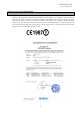
SATELLINE-EASy Pro User Guide v.1.5 PRODUCT CONFORMITY SATEL Oy hereby declares that SATELLINE-EASy Pro radio modem is in compliance with the essential requirements (radio performance, electromagnetic compatibility and electrical safety) and other relevant provisions of Directive 1999/5/EC. Therefore the equipment is labelled with the following CE-marking.
SATELLINE-EASy Pro User Guide v.1.5 WARRANTY AND SAFETY INSTRUCTIONS Read these safety instructions carefully before using the product: -Warranty will be void, if the product is used in any way that is in contradiction with the instructions given in this manual, or if the radio modem housing has been opened or tampered with. -The radio modem is only to be operated at frequencies allocated by local authorities, and without exceeding the given maximum allowed output power ratings.
SATELLINE-EASy Pro User Guide v.1.5 TABLE OF CONTENTS IMPORTANT NOTICE ......................................................................................... 1 RESTRICTIONS ON USE ..................................................................................... 2 PRODUCT CONFORMITY .................................................................................... 3 WARRANTY AND SAFETY INSTRUCTIONS ......................................................... 4 TABLE OF CONTENTS .......................
SATELLINE-EASy Pro User Guide v.1.5 7.1 Transmitter ........................................................................................... 24 7.2 Receiver ................................................................................................ 25 7.3 Priority RX/TX ....................................................................................... 25 7.4 Forward Error Correction ..................................................................... 26 7.5 Error checking ............
SATELLINE-EASy Pro User Guide v.1.5 9.2.3 9.2.4 9.2.5 9.2.6 9.2.7 9.2.8 9.2.9 9.2.10 9.2.11 9.2.12 9.2.13 9.2.14 9.2.15 9.2.16 9.2.17 Changing frequency (active radio channel frequency) .................................................. 42 Changing reference frequency ................................................................................... 43 Changing channel spacing ........................................................................................ 44 Changing radio settings ..............
SATELLINE-EASy Pro User Guide v.1.5 11.1 Introduction to Message Routing ......................................................... 80 11.2 Operating modes of Message Routing ................................................ 84 11.3 Detailed description of Message Routing ............................................ 85 11.1.1 11.1.2 11.1.3 11.1.4 11.1.5 11.1.6 11.3.1 11.3.2 11.3.3 11.3.4 12 Features of Message Routing ...................................................................................
SATELLINE-EASy Pro User Guide v.1.5 17 APPENDIX B ..................................................................................... 100 17.1 Functional delays ............................................................................... 100 17.2 Transmission related delays .............................................................. 100 17.2.1 17.2.2 17.2.3 Transmission delays when the radio TX frequency is changed ......................................
SATELLINE-EASy Pro User Guide v.1.5 INTRODUCTION SATEL OY is a Finnish electronics and Telecommunications Company specialising in the design and manufacture of wireless data communication products. SATEL designs, manufactures and sells radio modems intended for use in applications ranging from data transfer to alarm relay systems. End users of SATEL products include both public organisations and private individuals. SATEL OY is the leading European manufacturer of radio modems.
SATELLINE-EASy Pro User Guide v.1.
SATELLINE-EASy Pro User Guide v.1.5 Timing Electrical Interface Interface Connector Data speed of I/O-interface Data speed of Radio Interface Data Formats Modulation DATA MODEM RS-232 RS-232 8-pin ODU 300 – 38400 bps 19200 bps (25 kHz channel) / 9600 bps (12.5 / 20 kHz channel) Asynchronous RS-232 4FSK, GMSK, (PacificCrest, TRIMTALK **) **) TRIMTALK is a trademark of Trimble Navigation Ltd.
SATELLINE-EASy Pro User Guide v.1.5 1.
SATELLINE-EASy Pro User Guide v.1.5 When creating a test connection, you can use Windows™ based SATEL Configuration Manager (available for free from authorised SATEL dealers or directly from SATEL Customer Support), HyperTerminal (which is included in most the Windows™ based operating system packages), or almost any other terminal program.
SATELLINE-EASy Pro User Guide v.1.5 2 OTHER FEATURES SATELLINE-EASy Pro radio modem fulfils the IP67 (NEMA 6) standard. With an IP67 rating a product will be totally protected against dust and remain completely sealed when immersed in water to a depth between 15 cm and 1 meter. SATELLINE-EASy Pro modem is equipped with a high power 35 W transmitter. It is designed for easy mobile use in demanding field conditions.
SATELLINE-EASy Pro User Guide v.1.5 3 SATELLINE-EASy Pro SPECIAL FEATURES 3.1 Call Sign SATELLINE-EASy Pro has a CALL SIGN identifier -feature required in some countries. A call sign can be formally assigned by a government agency, informally adopted by individuals or organizations, or even cryptographically encoded to disguise identity of a station. A call sign is an FCC (in US) or other regulatory authority assigned identifier that is issued along with the license for operating a radio modem.
SATELLINE-EASy Pro User Guide v.1.5 The internal temperature is measured in the beginning of every transmission and at once when modem cools down. The carrier power increases with falling temperature so that at 88°C carrier power goes to 10W, at 83°C to 20W, at 78°C to 25W and at 73°C the modem operates again at the full 35W carrier power. 3.3 Protection of current In case of a bad antenna impedance matching the current consumption of the Power Amplifier may be too high.
SATELLINE-EASy Pro User Guide v.1.5 4 SERIAL INTERFACE The radio modem is referred to as DCE (Data Communication Equipment) whereas the PC is referred to as DTE (Data Terminal Equipment). SATELLINE-EASy Pro includes a 8 pin ODU which contains all the connections required to establish communication between the radio modem, acting as the DCE, and the PC, acting as the DTE. All EMC-requirements set forth by authorities have been taken into account in the design of the radio modem.
SATELLINE-EASy Pro User Guide v.1.5 5 USER INTERFACE 5.
SATELLINE-EASy Pro User Guide v.1.5 5.2.1 SATELLINE-EASy Pro LCD-display after power-up The display shows the basic information which is revolving automatically in 5 seconds. Display in Data Transfer Mode (transmit/receive mode) n-120 11.5V TX 438.000.000 RX 438.000.000 TX:35W SETUP n-120 11.5V Compatibility: Satel 3AS TX:35W SETUP n-120: Field strength of last received transmission or noise level. 11.5 = Supply voltage/battery level indicator. TX/RX = Operational TX and RX frequency.
SATELLINE-EASy Pro User Guide v.1.5 Display in Info mode. Pressing shows the next window. EASy-35W S/N: FW:06.18.3.52 Exit Product name Serial number FW: Firmware version TX 438.000.000 RX 438.000.000 Ref 438.000.000 Exit TX frequency RX frequency Reference frequency Band 1 limits Lo 403.000.000 Hi 473.000.000 Exit The modem can be limited to operate only on certain frequencies. The range is shown as LO=Low and HI=High. Band 2 limits Lo 403.000.000 Hi 473.000.
SATELLINE-EASy Pro User Guide v.1.5 6 CONNECTION INTERFACES NOTE! When installing the cables of the serial interface, it is recommended that the operating voltage of all devices is powered OFF. 6.1 RS-232 interface RS-232 standard defines the method of serial data transfer between a computer and its peripherals. The definition includes both the interface type and signal levels. Most computers and peripherals contain one or more RS-232 type serial ports.
SATELLINE-EASy Pro User Guide v.1.5 *) Programming Mode is for changing the settings of the radio modem via Programming menu. Normally the MODE line is NOT connected i.e. the radio modem is in Data Transfer Mode. 2.
SATELLINE-EASy Pro User Guide v.1.5 7 RF INTERFACE The SATELLINE-EASy Pro has a single TNC type RF-connector with impedance of 50 Ohm. When the modem is supplied the frequency is set to “default channel”. The user can change the frequency afterwards by 70 MHz. Of course, all local regulations set forth by the authorities must be taken into consideration. The data speed of the radio interface is set to “default speed”. It can also be set afterwards.
SATELLINE-EASy Pro User Guide v.1.5 7.2 Receiver The sensitivity of the receiver depends on the channel spacing of the radio modem (=data speed of the radio interface) and on the mode of the FEC (error correction) according to the table below: Channel spacing 25 kHz 20 kHz 12.5 kHz FEC OFF FEC ON -108 dBm -111 dBm -111 dBm -111 dBm -114 dBm -114 dBm The Signal Threshold Level setting of the receiver determines a level, above which the search for the actual data transfer signal is active.
SATELLINE-EASy Pro User Guide v.1.5 7.4 Forward Error Correction Forward Error Correction, FEC-function is switched ON (or OFF) by using the Programming Mode. When activated, the FEC-function will cause the SATELLINE-EASy Pro to automatically add additional error correction information, which increases the amount of transmitted data by 30 %. It is used by the receiving radio modem to correct erroneous bits - as long as the ratio of correct and erroneous bits is reasonable.
SATELLINE-EASy Pro User Guide v.1.5 When data flow on the TD line starts the frequency shifts from the receiving channel to the transmit channel. There is a 40 ms delay caused by the frequency shift before the actual data transmission sequence starts, and the same time is needed for the return to the receive channel after transmission. The selected channel spacing, port settings etc. are equal to both frequencies. The dual radio settings can be adjusted also by the SL commands. 7.
SATELLINE-EASy Pro User Guide v.1.5 7.8 User data whitening In some cases, if the user data includes a large number of constant characters, additional bit errors may appear. The use of error correction (FEC) is recommended in such cases. If that is not possible, the Data whitening feature can be used to improve the reliability of data transfer. The feature is set on/off in the programming mode.
SATELLINE-EASy Pro User Guide v.1.5 7.9.2 Configuration in Programming menu The correct radio compatibility mode can be changed in the Programming mode submenu Radio settings ->Radio compatibility Mode: Radio compatibility ------------------------1) Satelline-3AS 2) PCC 4-FSK 3) PCC GMSK 4) TRIMTALK GMSK, RX fitted to Pacific Crest transmitters 5) TRIMTALK GMSK, RX fitted to Trimble transmitters 6) PCC-FST 7.9.
SATELLINE-EASy Pro User Guide v.1.5 FEC = ON (FEC OFF state supported in PCC Transparent FST protocol implementation) Scrambling = ON Data Security Code set to = 0 (=not used) Local Address= 0…254 (0 by default) Pacific Crest modem receives messages from SATELLINE modems that have their TX1 address matching the Local Address. Remote address=0…255 (255 by default, that is the broadcast address to be received by all).
SATELLINE-EASy Pro User Guide v.1.5 Radio Link:Modulation Mode Radio Link:Scrambling Radio Link:Transmit Retries Radio Link:TX ACK Timeout Radio Link:Csma Monitoring Radio Link: AutoBase/AutoRover Radio Link:Digisquelch Radio Link:Forward Error Correction Radio Link:Local Address (0 by default) Radio Link:Remote Address (255 by default) Serial Interface:Protocol Mode Option 2 & 3: 9600bps@25kHz / 4800bps@12.5kHz Option 1: 19200bps@12.5kHz / 9600bps@12.
SATELLINE-EASy Pro User Guide v.1.5 7.9.5 Repeater function The implemented Pacific Crest/TRIMTALK modes support also the repeater function. The repeater function is configured either by using the SL commands: ”SL@M=R” (Repeater ON) ”SL@M=O” (Repeater OFF) or by selecting Repeater OFF/ON in the Additional setup-> Repeater programming menu. Note 1. The repeater modem passes TRIMTALK messages also to its serial port unlike for example Pacific Crest PDL modems. Note 2.
SATELLINE-EASy Pro User Guide v.1.5 The symbol rates for the Pacific Crest GMSK (Option2) are: 9600 bps on 25 kHz channel 4800 bps on 12.5 kHz channel The actual raw data rate is appr. 2/3 of the symbol rate. 7.9.7.1 Transmission delays using Pacific Crest 4FSK on 25 kHz channel The table below presents the typical latency vs. the size of the message. The delays are measured from the end of transmitted data to the end of received data on the serial interface.
SATELLINE-EASy Pro User Guide v.1.5 8 TRANSPARENT DATA TRANSMISSION 8.1 Serial interface, data format The SATELLINE-EASy Pro serial interface uses an asynchronous data format. No external synchronising signal is needed, since necessary timing information is acquired from the start and stop bits transmitted before and after each data field bits (byte). The data transfer speed of the serial interfaces can be set to 300, 600, 1200, 2400, 4800, 9600, 19200 or 38400 bps (bits per second).
SATELLINE-EASy Pro User Guide v.1.5 Handshaking is not needed if the system protocol is designed to prevent collisions (data contention) by the use of polling, or if there is little traffic and also if there is no harm from occasional data contention situations (several radio modems try to transmit at the same time). 8.2.1 CTS-line The options for CTS-line are: 1) Clear To Send CTS is active when the radio modem is ready to accept data for new transmission.
SATELLINE-EASy Pro User Guide v.1.5 2) Data on channel CD will switch to active state only after recognition of a valid data transmission. CD will not react to interference signals. 3) Always ON CD is always in the active state. This option can be used with terminal equipment, which use the CD-line as an indicator of an active connection (the radio modem can transmit and receive at any time). 4) External Antenna Control 8.2.3 RTS-line The options for RTS-line are: 1) Ignored RTS-line status is ignored.
SATELLINE-EASy Pro User Guide v.1.5 after all buffered data has been transmitted. When the serial interface speed is the same or slower than the speed of the radio interface, the internal transmit buffer memory cannot overflow. However, when the serial interface speed exceeds the speed of the radio interface, data will eventually fill transmit buffer memory.
SATELLINE-EASy Pro User Guide v.1.5 8.3.3 TX delay The radio modem can be configured to delay the beginning of a radio transmission by 1...65000ms. This function can be used to prevent packet contention in a system, where all substations would otherwise answer a poll of a base-station simultaneously. During this delay data sent to the radio modem is buffered. Although the priority setting is "RX", radio modem is prevented to change over to receiving mode during the period of the TX delay.
SATELLINE-EASy Pro User Guide v.1.5 The strength of the received signal can be monitored using the LCD-display of the receiving radio modem. NOTE 1! Green TD led indicates active test mode. NOTE 2! Normal data transfer is not available while the Test mode is active. Remember to switch it OFF before starting the normal data transfer. NOTE 3! Message Routing and FCS mode must be disabled prior to set ON the Test mode.
SATELLINE-EASy Pro User Guide v.1.5 9 SETTINGS The configuration of SATELLINE-EASy Pro can be easily changed. Simply by connecting MODE pin (see chapter 6.2) of the data connector to ground (GND) the radio modem will switch into Programming Mode. Serial PORT 1 is used whenever the radio modem is in the Programming Mode. The serial port settings are 9600 bps, N, 8,1 (data transfer speed 9600 bps, none parity, character length 8 bits and one (1) stop bit).
SATELLINE-EASy Pro User Guide v.1.5 Connect MODE-pin to ground (if using the NARS-1F adapter, slide the switch downwards), the radio modem shifts now into the Programming Mode. The screen should look similar to the one shown in the picture below. Make desired changes to the settings with SaTerm. Save changes by pressing ”E” in the main menu. If you don’t want to save changes, press ”Q”.
SATELLINE-EASy Pro User Guide v.1.5 Restore factory settings -----------------------Do you want to restore factory settings? (Y/N)> PORT 1 of the radio modem is connected to a terminal device or a PC, which is in terminal emulation state. (This can be accomplished by using a suitable program such as the SaTerm program or the Windows™ Hyper Terminal program). Check the wiring of the serial port connection cable.
SATELLINE-EASy Pro User Guide v.1.5 Enter selection or ESC to previous menu >1 Radio TX and RX frequency setup ------------------------------1) TX and RX frequency 2) TX frequency 468.52500 MHz 3) RX frequency 437.00000 MHz 4) Reference frequency 438.00000 MHz Enter selection or ESC to previous menu >2 Radio TX frequency setup -----------------------TX frequency 468.52500 MHz RX frequency 437.00000 MHz Lower limit band 1 403.00000 MHz Upper limit band 1 473.00000 MHz Lower limit band 2 403.
SATELLINE-EASy Pro User Guide v.1.5 Enter selection >1 Radio frequency setup --------------------1) Radio frequency 2) Channel spacing Enter selection or ESC to previous menu >1 Radio TX and RX frequency setup ------------------------------1) TX and RX frequency 2) TX frequency 468.50000 MHz 3) RX frequency 437.00000 MHz 4) Reference frequency 438.00000 MHz Enter selection or ESC to previous menu >4 Radio reference frequency setup ------------------------------Reference frequency 438.
SATELLINE-EASy Pro User Guide v.1.5 1) 12,5 kHz 2) 20 kHz 3) 25 kHz Enter selection or ESC to previous menu > ESC Radio frequency setup --------------------1) Radio frequency 2) Channel spacing 12,5 kHz To get back to the main menu press ESC and then E for Exiting and saving. 9.2.6 Changing radio settings Radio settings which consist of transmitter output power and receiver sensitivity can be configured by selecting main menu selection ”2”.
SATELLINE-EASy Pro User Guide v.1.5 The maximum useable sensitivity of the receiver is determined by the channel spacing (=radio interface data transfer speed) and also by error correction (utilised or not). In environments with high levels of interference, and when connection distances are short, it is often beneficial to use a ”Signal threshold level” value, which is approximately 10 – 20 dBm above the maximum sensitivity level. This will prevent unnecessary receive attempts caused by noise.
SATELLINE-EASy Pro User Guide v.1.5 The hardware information can be seen in the main menu ***** SATELLINE ***** FW: 06.18.x.xx / HW: SPL0005d+EPT / PV: 05.00 / IM: 05 / S/N: 30032010 ---------------------------------------------------------------------------- FW= Firmware HW=Hardware version PV=Product variant version IM=Interface module (Voltage range and interface type) S/N= serial number. 9.2.
SATELLINE-EASy Pro User Guide v.1.5 The new value is displayed in the menu. To get back to the main menu press ESC (and then E for Exiting and saving). The address is given in hexadecimal format with four digits and the number of different addresses is thus over 65 000. 9.2.9 Changing serial port settings (Port 1) The settings of serial PORT 1 can be modified by selecting main menu selection ”4”.
SATELLINE-EASy Pro User Guide v.1.
SATELLINE-EASy Pro User Guide v.1.5 Now all of the modifications of the example have been performed and the new values are displayed: ***** SATELLINE ***** FW: 06.18.x.xx / HW: SPL0005d+EPT / PV: 05.00 / IM: 05 / S/N: YYMMxxxx ------------------------------------------------------------------------------Current settings ---------------1) Radio frequency TX: 468.50000 MHz / RX: 437.00000 MHz / Ref freq: 460.00000 MHz / Spacing 12.
SATELLINE-EASy Pro User Guide v.1.5 Number 6 is pressed in the Main menu.
SATELLINE-EASy Pro User Guide v.1.5 Now all of the modifications of the example have been performed and the new values are displayed on the menu as follows: ***** SATELLINE ***** FW: 06.18.x.xx / HW: SPL0005d+EPT / PV: 05.00 / IM: 05 / /N: YYMMxxxx ------------------------------------------------------------------------------Current settings ---------------1) Radio frequency TX: 438.00000 MHz / RX: 450.00000 MHz / Ref freq: 438.
SATELLINE-EASy Pro User Guide v.1.5 9.2.12 Modification of routing Configuration settings defining routing can be changed by selecting main menu selection ”8”.
SATELLINE-EASy Pro User Guide v.1.
SATELLINE-EASy Pro User Guide v.1.
SATELLINE-EASy Pro User Guide v.1.
SATELLINE-EASy Pro User Guide v.1.5 9.2.13 Activating tests Tests can be activated by selecting main menu selection ”9”. Tests are activated by setting the status of the desired test to ”ON” and will remain active until the value of the selection in the menu is returned to the value ”OFF”. Enter selection >9 Tests setup ----------1) Short block test 2) Long block test OFF OFF NOTE! Message Routing and FCS mode must be disabled in prior to set ON the Test mode. 9.2.
SATELLINE-EASy Pro User Guide v.1.5 9.2.16 Saving modified settings into the permanent memory All modified settings must be saved into the permanent non-volatile memory of the radio modem before switching out of the Programming Mode. Selecting the main menu selection “E” automatically saves the settings: Enter selection >E Configuration saved! Please turn off program mode switch! NOTE! To switch the radio modem back into Data Transfer Mode the MODE-pin of the must be disconnected from ground (GND).
SATELLINE-EASy Pro User Guide v.1.5 value have been edited. Toggle-type parameters (typically with ON/OFF choices modifications have to be confirmed by pressing the ”SELECT”- or ”SET”-button. This is the display in Data Transfer Mode. TX and RX frequencies are set to 468.525.000 MHz. Compatibility is Satel 3AS. TX power is 35W. Channel spacing is 25 kHz. Reference frequency is 438.000.000 MHz. Serial PORT 1 settings are 19200, N, 8, 1.
SATELLINE-EASy Pro User Guide v.1.5 TX & RX freq: changes both TX and RX frequencies at the same time. TX freq: changes only the TX frequency. RX freq: changes only the RX frequency. Press ▲ or ▼ until the cursor > points at the correct selection and Press ”CHANGE” if the frequency is to be modified. >TX & RX freq TX freq RX freq Reference freq Ch Spacing BACK ▲▼ Change Band 1 limits Lo 403.00000 MHz Hi 473.00000 MHz TX & RX freq selected The frequency Band 1limits will be shown.
SATELLINE-EASy Pro User Guide v.1.5 9.3.2 CHECKING/CHANGING THE REFERENCE FREQUENCY >Radio frequency Radio settings Addressing Port 1 Press SETUP, set cursor at the Radio frequency and Port 2 press Select. Handshaking Additional Tests Factory setup Contrast EXIT▲▼Select Press ▲ or ▼ until the cursor points at “Reference freq” selection and press ”Change”. TX & RX freq TX freq RX freq > Reference freq Ch Spacing Back ▼ Change Band 1 limits are shown.
SATELLINE-EASy Pro User Guide v.1.5 The display will now show New Ref freq 438.00000 MHz The cursor > will now blink under the first digit of the value indicating the (this first digit cannot be edited). To move onto the next digit, press ”Next”. Previous steps are repeated four (4) times. Press ▲ or ▼, until the last changeable digit has the desired value and confirm changes by pressing ”Set”. The following information will be displayed for a few seconds. New common freq 468.
SATELLINE-EASy Pro User Guide v.1.5 min -118 dBm > -117 dBm -116 dBm . . -81 dBm -80 dBm max MODIFYING RECEIVER SENSITIVITY: The displayed list consists off all possible values of receiver sensitivity. Press ▲ or ▼ until the cursor > points to the desired value and press ”SET”. NOTE: The starting position of the cursor indicates the previously set value. CANCEL ▲ ▼ SET MODIFYING THE TRANSMIT START DELAY: The display will show the current value of the delay. Press ”Change” to modify the value.
SATELLINE-EASy Pro User Guide v.1.5 >Call sign OFF Call sign ON The display will show the current value. Press ▲ or ▼ until the cursor > points to the desired value and press ”SET”. Cancel ▲▼ Set 9.3.4 Changing addressing Radio frequency Press ▲ or ▼ until Radio settings >Addressing the cursor > Port 1 points to Port 2 “Addressing” Handshaking selection and Additional press ”SET-UP” to Test move on to the Factory setup submenu.
SATELLINE-EASy Pro User Guide v.1.5 9.3.5 Changing serial port settings (Port 1) NOTE! The radio modem has one serial port, PORT 1 which complies with the RS-232 standard. PORT 2 is not in use and the settings of serial PORT 2 cannot be changed. Radio frequency Radio settings Addressing Press ▲ or ▼ until the cursor > >Port 1 points to the desired port (in this Port 2 example to Port 1) and move on Handshaking Additional to the submenu by pressing Tests ”SELECT”.
SATELLINE-EASy Pro User Guide v.1.5 MODIFICATION OF THE NUMBER OF STOP BITS: Press ▲ or ▼ until the cursor > points to the desired number of STOP bits. Confirm selection by pressing ”SET”. The display will return to the previous (higher) level submenu. NOTE: The starting position of the cursor indicates the previously set value. >1 stop bit 2 stop bits Cancel ▲▼ Set 9.3.
SATELLINE-EASy Pro User Guide v.1.5 9.3.7 Selecting special functions Press ▲ ▼ until the cursor > points to “Additional” selection and press ▼ ”SELECT” to move on to the submenu. Radio frequency Radio settings Addressing Port 1 Port 2 Handshaking >Additional Test Factory setup LCD-Contrast Exit ▲▼ Select Press ▲ or ▼ until the cursor > points to the setting to be modified. Press ”CHANGE” to toggle the status of the said parameter from ”ON” to ”OFF” and vice versa.
SATELLINE-EASy Pro User Guide v.1.5 9.3.9 Restoring factory settings Radio frequency Radio settings Addressing Press ▲ or ▼ to move cursor > Port 1 Port 2 to point to “Factory set-up” selection and press ”SELECT” to Additional Test move on to the submenu. >Factory setup LCD-Contrast Exit ▲▼ Select Press ”YES” and all radio modem configuration settings will return to factory settings (which are the ones that the modem was delivered). 9.3.
SATELLINE-EASy Pro User Guide v.1.5 9.3.11 Saving modified values into the internal memory After all desired modifications have been performed; they have to be saved in order to make them permanent (until next modification). This is accomplished by choosing selection ”EXIT” from the main menu. The display will then show a message (see below) asking a confirmation of the performed modifications. By choosing ”YES” all modifications are saved into the non-volatile memory inside the radio modem.
SATELLINE-EASy Pro User Guide v.1.5 In case you need more information on the time delays related to the use of SL-commands, please contact the manufacturer. In order to get information of the latest and/or special SL-commands please contact SATEL Oy. 9.4.1 Frequency Command Effect and description of command SL&FR=nnn.nnnnn Set RX-frequency to nnn.nnnnn MHz SL&FT=nnn.nnnnn Set TX-frequency to nnn.nnnnn MHz SL&F=nnn.nnnnn Set both RX&TX-frequency to same nnn.
SATELLINE-EASy Pro User Guide v.1.5 9.4.
SATELLINE-EASy Pro User Guide v.1.5 9.4.4 Other functions Command Effect and description of command SL**> Set current settings as permanent settings. This command must be used only seldom and under controlled conditions in order to avoid the corruption of the settings, which may happen in case the power supply fails in the middle of the memory save procedure. Get Firmware revision information (response ’Vn.
SATELLINE-EASy Pro User Guide v.1.5 10 REPEATER MODE AND ADDRESSING Repeaters and addressing may be used to extend the coverage area of a radio modem network, and to direct messages to selected radio modems in the network. In large systems, with several repeaters and formed repeater chains, it is often practical to use routing instead of plain addresses. 10.
SATELLINE-EASy Pro User Guide v.1.5 10.2 Addressing Addresses can be used to route a data message to the desired destination or to separate two parallel networks from each other. In networks with repeaters it is usually necessary to use addresses to prevent data messages from ending up in loops formed by repeaters. In case of setting the “Message Routing” function in use, Tx / Rx addresses are ignored by the modem.
SATELLINE-EASy Pro User Guide v.1.5 Transmission: Transmission address has been set OFF. Radio modem will transmit the data packet as such. Transmission addressing has been set ON. The radio modem will add the primary TX address to the beginning of the data packet. Reception: Reception addressing has been set ON and either the primary or secondary RX address of the radio modem is identical to the address of the received data packet.
SATELLINE-EASy Pro User Guide v.1.5 Reception addressing has been set OFF. Reception addressing been set OFF. The radio modem will transfer all received data to the RS-232 interface. The radio modem will consider the characters of the address as a part of the data and will send all the characters to the RS-232 interface. 10.2.1 has Reception addressing has been set ON but there is no address in the data packet.
SATELLINE-EASy Pro User Guide v.1.5 For example, if the substation terminal devices are not able to check and form addresses by themselves, addressing may be achieved with the help of the addresses of the radio modems attached to these terminal devices. The base station may, in such a case, define the destination of a message by adding the address of the corresponding radio modem into the beginning of the data packet.
SATELLINE-EASy Pro User Guide v.1.5 S ADD DATA - The above is the same message after being relayed from the last repeater in the chain (repeater 2) to the substation. DATA - The above is the same message being relayed via the serial interface of the substation radio modem to the terminal device.
SATELLINE-EASy Pro User Guide v.1.5 10.3.3 Repeater chain using dual addressing If the terminal devices cannot add address chains to the beginning of the data packets, a network with several repeaters may still be realised by using dual addressing. In dual addressing each link (see arrows below in figure) is given a unique address, which will prevent duplication of messages and endless loops in the network. The terminal devices need not add anything to the data.
SATELLINE-EASy Pro User Guide v.1.5 11 MESSAGE ROUTING 11.1 Introduction to Message Routing Message Routing is an exciting feature in SATELLINE-EASy Pro. This feature allows messages from terminal devices to be automatically routed over the radio modem network to a specified recipient terminal. In brief, the Message Routing works as follows: First, a radio modem reads any message coming from the terminal(s) attached to it.
SATELLINE-EASy Pro User Guide v.1.5 11.1.1 Features of Message Routing The Message Routing feature of the SATELLINE-EASy Pro is designed to be a fast and transparent to fit real time systems. The features include: Transparent to user protocols. Easy construction of a network containing several repeaters. Any radio modem may operate as a repeater, i.e. dedicated repeaters are not usually needed thus cutting down on costs. Large areas of coverage may be implemented by using only one radio channel.
SATELLINE-EASy Pro User Guide v.1.5 3. Configure the radio modems accordingly. There are two ways to configure the parameters related to the Message Routing: 1. SaTerm PC-program 2. Manual configuration in the setup menu. In either case, please check the chapter on Settings before changing the setup of the radio modems. Finally, when all the radio modems have correct settings, they are ready for further installation. 11.1.
SATELLINE-EASy Pro User Guide v.1.5 several overlapping networks. The operation of the Message Routing must be clearly understood before configuring the radio modems manually. 11.1.6 Configuration of the protocol in Message Routing A radio modem will detect the presence of an address used by inspecting the protocol from the message received via the serial interface.
SATELLINE-EASy Pro User Guide v.1.5 11.2 Operating modes of Message Routing The Message Routing has two different operating modes: Source Mode Routing Virtual Mode Routing The most important differences between the two modes are shown in the table below.
SATELLINE-EASy Pro User Guide v.1.5 11.3 Detailed description of Message Routing 11.3.1 Source Mode Routing 3 0 1 Z X Järjestelmä Y Z 2 Modeemi 1, 2 1, 3 Y The above figure represents a network containing four (4) radio modems. Each radio modem is given a unique address (0…3). A terminal device has been attached to the three of the four radio modems and they communicate with each other using terminal addresses X, Y and Z, respectively.
SATELLINE-EASy Pro User Guide v.1.5 11.3.3 Overhop function in Source Mode Routing t M as t er TD R a d io S u b s t a t io n M M as t er R1 R2 RD R1 R2 TD S RD When using repeaters, the same packet is sent via a (radio) channel several times. A radio modem situated in the repeater chain will often hear other radio modems in addition to the immediate neighbouring radio modems.
SATELLINE-EASy Pro User Guide v.1.5 R1 M R2 The overhop function allows for the use of mobile substations. In the example above, a mobile substation is first located in the coverage area of repeater R2. The route is defined as M, R1, R2 and vehicle. When the vehicle moves to the coverage area of repeater R1, the radio modem picks the packet already from the transmission of R1.
SATELLINE-EASy Pro User Guide v.1.5 12 INSTALLATION 12.1 Installation of a Radio Data Modem The radio modem should be installed with the installation accessories supplied with the radio modem. NOTE! When selecting a suitable location for the radio modem it must be ensured that no water can get into the radio modem under any conditions. Direct sunlight is also to be avoided. It is not recommendable to install the radio modem on a strongly vibrating surface.
SATELLINE-EASy Pro User Guide v.1.5 12.1.2 Fuse A proper fuse must be connected in between the radio modem and the power supply. The correct value is 15A for SATELLINE-EASy Pro. 12.1.3 Power supply The allowed operating voltage is +9 ... +16 VDC. The radio modem must only be connected to a power supply with an adequate current output (power rating minimum is 120W). The pins 1 and 2 of the 4pin Odu-connector are connected to the positive power supply line.
SATELLINE-EASy Pro User Guide v.1.5 12.2 Antenna installation NOTE! Because of the great transmission power of SATELLINE-EASy Pro radio modem, only an external antenna is allowed. A whip-antenna directly connected to the antenna connector must not be used. 12.2.1 Mobile equipment ¼-wave antenna ½-wave antenna The ideal installation position is vertical, and there should be at least 0.5 m of free space around the antenna. In small systems a ¼-wave antenna is sufficient.
SATELLINE-EASy Pro User Guide v.1.5 withstand all foreseeable weather conditions (frost, excess sun, direct UV-radiation, seawater etc.). Also possible environmental pollution must be considered (acids, ozone etc.). Antennas must be installed well away from metallic objects. In the case of small antennas this distance should be at least ½ m. With large antennas the distance should be >5 m and in case of repeater antenna combinations >10 m.
SATELLINE-EASy Pro User Guide v.1.5 positive result of the quality of the connection. Thus the height of the antennas and topographical obstacles must be surveyed with great care. From time to time a marginal connection can be used if the data transmission protocol is well prepared for this and the data transmission that occasionally slows down does not cause any problems to the system. Vertical polarised antennas (antenna elements are in vertical position) are often used in radio systems.
SATELLINE-EASy Pro User Guide v.1.5 Example of an antenna installation: by using amplifying antennas (G=Gain) and by installing the antenna high, long connection distances can be realised using the SATELLINE-EASy Pro radio modem.
SATELLINE-EASy Pro User Guide v.1.5 13 DESIGNING SYSTEMS 13.
SATELLINE-EASy Pro User Guide v.1.5 13.2 Radio field strength Radio signal strength must be good enough for successful data transfer. Where field strength is above a certain level, the operational results are very good. Below this level, a few dB marginal areas occur in which errors begin to be generated by noise and interference that will eventually lead to loss of connection. The field strength is at its optimum level in open space, although increasing distance will still reduce it.
SATELLINE-EASy Pro User Guide v.1.5 14 CHECK LIST The following points must be taken into account when installing and configuring a radio modem: 1. All operating voltages of all the equipment concerned must always be switched OFF before connecting the serial interface cable. 2.
SATELLINE-EASy Pro User Guide v.1.5 15 ACCESSORIES 15.1 RS-232 cables and adapters Type ODU/D9f NARS-ST Description 8 pin ODU / D9 female (universal). 8 pin; for EASy Pro 35W Contact SATEL Oy for more detailed information about other serial interface cable options. 15.2 Power cable Type C-P-35W Description 2m cable, ODU 4-pin male / 4mm lab plug Contact SATEL Oy for more detailed information about other power cable options. 15.
SATELLINE-EASy Pro User Guide v.1.5 15.
SATELLINE-EASy Pro User Guide v.1.
SATELLINE-EASy Pro User Guide v.1.5 17 APPENDIX B 17.1 Functional delays Function Wakeup time from STAND-BY to ON (controlled by DTR line) Wakeup time from Power OFF -> Power ON (=ready to receive) Serial interface, turnaround time of RS-232 TX-mode: Wakeup time from SLEEP to modem ready (triggered by IRQ-data when Data in TDinput). RX-mode: Wakeup time from SLEEP to modem ready (triggered by IRQ-data when Data in TDinput). RD - TD turnaround wait, if RX freq. TX frequency.
SATELLINE-EASy Pro User Guide v.1.5 17.2.1 Transmission delays when the radio TX frequency is changed If the modem’s transmitter frequency (TX) is different than the receiver frequency (RX), there has to be at least 40 ms delay from the Receive Data (RD) to Transmit Data (TD). If the transmitter frequency is changed by an SL-command, there has to be at least 40 ms delay after the SL-command before the Transmit Data.
SATELLINE-EASy Pro User Guide v.1.5 Transmission delays with FEC-function (Forward Error Correction). Bps 1200 4800 9600 19200 38400 1 52 45 44 44 48 Number of bytes sent 10 49 45 44 44 48 100 48 44 68 104 132 500 50 44 121 360 496 Delays are in milliseconds and with a 10% margin. 12.
SATELLINE-EASy Pro User Guide v.1.5 17.2.3 Transmission delays using a 25 kHz radio channel Transmission delays without FEC-function (Forward Error Correction). Number of bytes sent Bps 1 10 100 1200 30 30 18 4800 23 23 21 9600 23 23 21 19200 22 22 22 38400 22 22 38 500 16 12 17 19 102 Delays are in milliseconds and with a 10% marginal.
SATELLINE-EASy Pro User Guide v.1.5 Transmission delays with FEC-function (Forward Error Correction). Bps 1200 4800 9600 19200 38400 1 35 28 28 28 27 Number of bytes sent 10 34 28 28 28 27 100 29 27 28 36 58 500 30 23 23 64 185 Delays are in milliseconds and with a 10% margin.