SATELLINE®-M3-R3 RADIO RECEIVER MODULE USER GUIDE Version 1.
SATELLINE-M3-R3 User Guide, Version 1.2 IMPORTANT NOTICE All rights to this manual are owned solely by SATEL OY (referred to in this user guide as SATEL). All rights reserved.
SATELLINE-M3-R3 User Guide, Version 1.2 RESTRICTIONS ON USE SATELLINE-M3-R3 radio modem module has been designed to operate on frequency ranges, the exact use of which differs from one region and/or country to another. The user of a radio modem must take care that the said device is not operated without the permission of the local authorities on frequencies other than those specifically reserved and intended for use without a specific permit.
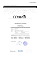
SATELLINE-M3-R3 User Guide, Version 1.2 PRODUCT CONFORMITY Hereby, SATEL Oy declares that SATELLINE-M3-R3 radio modem module is in compliance with the essential requirements (radio performance, electromagnetic compatibility and electrical safety) and other relevant provisions of Directive 1999/5/EC. Therefore the equipment is labelled with the following CE-marking.
SATELLINE-M3-R3 User Guide, Version 1.2 WARRANTY AND SAFETY INSTRUCTIONS Read these safety instructions carefully before using the product: -Warranty will be void, if the product is used in any way that is in contradiction with the instructions given in this manual, or if the radio modem housing has been opened or tampered with. -The radio modem module is only to be operated at frequencies allocated by local authorities, and without exceeding the given maximum allowed output power ratings.
SATELLINE-M3-R3 User Guide, Version 1.2 TABLE OF CONTENTS IMPORTANT NOTICE ............................................................................................. 1 RESTRICTIONS ON USE ......................................................................................... 2 PRODUCT CONFORMITY ........................................................................................ 3 WARRANTY AND SAFETY INSTRUCTIONS ............................................................. 4 TABLE OF CONTENTS ...
SATELLINE-M3-R3 User Guide, Version 1.2 3.8 Restart ...................................................................................................... 16 3.9 Startup sequence ..................................................................................... 17 3.10 Shutdown sequence ................................................................................. 18 3.11 Time parameters for start-up and shutdown sequences ........................ 19 3.12 Stat pin ...........................
SATELLINE-M3-R3 User Guide, Version 1.2 1. INTRODUCTION SATEL OY is a Finnish electronics and Telecommunications Company specialising in the design and manufacture of wireless data communication products. SATEL designs, manufactures and sells radio modems intended for use in applications ranging from data transfer to alarm relay systems. End users of SATEL products include both public organisations and private individuals. SATEL OY is the leading European manufacturer of radio modems.
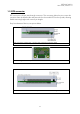
SATELLINE-M3-R3 User Guide, Version 1.2 1.3 DTE connector DTE connector is 20-pin pass-through connector. This connector allows the pin to enter the connector from the bottom side and protrude thru the module PCB to the top side, allowing flexible mounting heights with various pin lengths. Entry from bottom of device, see picture below. Side view of the module with 1.27mm pitch connector and screw fixing. Pin numbering of 1.27 mm pitch DTE connector.
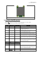
SATELLINE-M3-R3 User Guide, Version 1.2 Pin numbering of 1.27 mm pitch DTE connector. View from top side of unit 1.4 Pin order of the DTE connector Direction IN is data from DTE (Data Terminal Equipment) to the radio modem. Direction OUT is data from the radio modem to the DTE. Pin No.
SATELLINE-M3-R3 User Guide, Version 1.2 18 19 GPIO11 PPS CMOS/BIDIR CMOS/IN 20 REF_FREQ_IN CMOS/IN Pull low / drive low to set UART1 (RD1,TD1) into known state. See separate section of manual. GPIO – not used Pulse per second input. A CMOS input for pulse per second signal output from GPS receivers. Intended to sync time and frequency of receiver to other radios. Frequency input. A 1MHz…20 MHz input. Generally from a GPS receiver clock. Used for reference frequency synchronization.
SATELLINE-M3-R3 User Guide, Version 1.2 2 MECHANICAL CONSIDERATIONS 2.1 Fixing device to host The radio module can be mounted on to the host by using spacers and screws. Max. screw diameter is 3mm. 2.2 Sheet-metal standoff In space constrained applications, where there is no room for using screw for fixing, the device can be soldered on to the host board by using metal clips which are part of the bottom shielding of the device.
SATELLINE-M3-R3 User Guide, Version 1.2 Picture. The two different standoffs in a close-up. Picture . Open and closed standoff. Screw fixings can be cut off on the drill line.
SATELLINE-M3-R3 User Guide, Version 1.2 2.3 Soldering / host board instructions for mounting pegs Drill pattern R 1,60 Soldering area Hole for long pegs Hole for short pegs 34,8 SCALE 2:1 Min 0.6 12,5 12,00 3,0 Min. 1,5 20,00 50,00 26,00 17,4 14,5 14,5 3,0 20,00 2,0 Picture. Host board solders instructions.
SATELLINE-M3-R3 User Guide, Version 1.2 3 CHANGING PARAMETERS USING SL-COMMANDS The controlling terminal device can change the configuration settings of the module. This is accomplished with the help of SL-commands, which can be used during data transfer. SLcommands can be used to change e.g. the frequency or addresses. It is also possible to ask the radio modem to show current settings which are in use.
SATELLINE-M3-R3 User Guide, Version 1.2 PS-mode Receiver ON/OFF 1. When started, 7 messages are analyzed and the average is calculated. The ON/OFF interval (plus some margin) is selected according to the shortest and modem is switched OFF. Modem will be switched on 60ms prior to next message. 2. The interval is measured all the time from every message. 3. If the interval is shorter than 10ms from average, additional 1ms is added to the average value. 4.
SATELLINE-M3-R3 User Guide, Version 1.2 3.5 Turn ON using command When being in either off or sleep mode, the modem will be automatically wake up after the CPU senses a state change in the TD1 pin. The first data byte is lost because the CPU UART is shut off, and is not able to read data.
SATELLINE-M3-R3 User Guide, Version 1.2 3.9 Startup sequence The following diagram will describe the startup sequence. STARTUP SEQUENCE VCC_IO SUPPLIED EXTERNALLY Tvic VCC_IN Tioms ENA_MODEM VCC_IO Tiovs IO-LINES ”Z” ”X” Figure. Startup sequence with VCC_IO supplied externally. STARTUP SEQUENCE VCC_IO SUPPLIED INTERNALLY Tvic VCC_IN Tioms+ Tiovs ENA_MODEM IO-LINES ”Z” ”X” Figure.
SATELLINE-M3-R3 User Guide, Version 1.2 3.10 Shutdown sequence The following diagram will describe the shutdown sequence. SHUTDOWN SEQUENCE VCC_IO SUPPLIED EXTERNALLY TIdof VCC_IN Tiovf ENA_MODEM Tior VCC_IO IO-LINES ”X” ”Z” Figure. Shutdown sequence with VCC_IO supplied externally. SHUTDOWN SEQUENCE VCC_IO SUPPLIED INTERNALLY TIdof VCC_IN ENA_MODEM Tior IO-LINES ”X” ”Z” Figure. Shutdown sequence with VCC_IO supplied internally.
SATELLINE-M3-R3 User Guide, Version 1.2 3.11 Time parameters for start-up and shutdown sequences Parameter Min time Recom. Time (* Explanation Tvic 0 >50µs When voltage is applied to VCC_IN the filter Input capacitor charge time capacitors inside the module are charged, creating a small current surge. If the feeding power supply is not very strong it is recommended to wait this time before rising ENA_MODEM to minimize current surge.
SATELLINE-M3-R3 User Guide, Version 1.2 3.12 Stat pin The STAT pin indicates the status of the device. It can be used to drive a LED using a series resistor. STAT pin drive capability is 10mA (loads the VCC_IO if provided externally). The STAT pin has the following behavior. Blink cycle “1” - statically “0” for the endurance of the received frame.
SATELLINE-M3-R3 User Guide, Version 1.2 4 TECHNICAL SPECIFICATIONS SATELLINE-M3-R3 complies with the following international standards: EN 300 113-1 V.1.6.2 (RF) EN 301 489 (EMC-requirements) EN 60950 (Safety Standard) FCC CFR47 PART 15 Frequency Range Frequency Control Channel Bandwidth Tuning range Sensitivity Co-channel Rejection Adjacent Channel Selectivity Intermodulation Attenuation Blocking Spurious Rejection Power Consumption, typical Power Consumption Timing RECEIVER 403...473 MHz Synthesized 6.
SATELLINE-M3-R3 User Guide, Version 1.2 GENERAL Operating Voltage Temperature Range 4.0 VDC -25°C...+55°C. Temperature Ranges -30 °C ... +70 °C -25 °C ... +55 °C Vibration -40°C … +85°C ISO 9022-36-08 (sinus/ 10Hz-500Hz/ +/-0.35mm/5g/ 1 Oct./min/ 10 cycles/ each axis) OPERATING. Antenna Connector Construction Size L x W x T Weight Type approval condition Functional Complies with standards Storage Tested as a standalone unit (mounted PCB), mount on a test fixture simulating a typical DTE.
SATELLINE-M3-R3 User Guide, Version 1.2 4.2 DC electrical specifications Over recommended operating conditions Parameter VCC_IN ENA_modem, Vlow ENA_modem, Vhigh Logic input, Vlow Logic input, Vhigh Logic output, Vlow Logic output, Vhigh Logic output, max current Logic output, max current, STAT pin Condition 4.0V is considered nominal 1.8V
SATELLINE-M3-R3 User Guide, Version 1.2 5 DEFAULT DELIVERY VALUES DEFAULT VALUES OF THE ADJUSTABLE SETTINGS ( the user can change these settings later on ) Setting Radio frequency Operating RX frequency Reference Frequency Channel Spacing Default value Range 438.000 MHz 438.000 MHz 25 kHz Range: 403-473 MHz Range: 403-473 MHz Range:12.
SATELLINE-M3-R3 User Guide, Version 1.2 6 CONSIDERATIONS 6.1 Emi Interferers The module is designed to be mounted inside a host device. The module is designed to withstand EMI even beyond type approval requirements. However, a small module which is integrated closely to modern high speed electronics is bound to receive some interference. To make a working integration consider the following.
SATELLINE-M3-R3 User Guide, Version 1.2 6.2 Electrostatic discharge As the module is intended to be embedded in a host application, in a typical use case, the antenna port is the only port of the module directly interface with a surface or contact area subjected to Electrostatic Discharge (ESD). Thus, the antenna port is the only interface with high level ESD protection.