RFID USER GUIDE (Alien C1 UHF) PN 9001147B
SATO America, Inc. 10350A Nations Ford Road Charlotte, NC 28273 Main Phone: (704) 644.1650 Technical Support Hotline: (704) 644.1660 Technical Support Fax: (704) 644.1661 E-Mail: satosales@satoamerica.com techsupport@satoamerica.com www.satoamerica.
SCOPE This document is to serve as a guide on how to create RFID data using Label Gallery Plus/ TruePro software. It will include menu selection and all relative command code sequences. OVERVIEW The Alien Technologies RFID Reader and antenna are integrated into printer among the standard components. A data cable connects the main circuit board to the RFID Reader. The Reader is, in turn, connected to the antenna by its own antenna cable.
RFID HARDWARE CONFIGURATION The RFID hardware kit is comprised of the: RFID Module, RFID Antenna w/coaxial cable, RFID Cable Set. The figure below displays configuration: RFID ANTENNA SPECIFICATIONS Module 85.47 x 53.98 x 7.62 mm (sealed in a shield case) Antenna 16 x 118 x 1.
EXT CONNECTOR The EXT Port pin-out information for the RFID has changed slightly to accomodate the addition of a “tag error” output. The tag error output is available on PIN 3. The “Ribbon Out” output, formerly found at PIN 3, has been combined with the “Label Out” output on PIN 1. PIN 1 will now provide a “Media Out” (ribbon and/or label) error. The PIN 3 signal polarity is the same for “tag Error” as it was for “Ribbon Out” previously.
RFID SPECIFIC MENU ITEMS The LCD menu items specific to RFID are located in the Service Mode menu area. To reach the Service Mode menu area, power the printer on while pressing and holding the LINE and FEED keys. Release the keys upon hearing the printer beep. Press the LINE key twice, and then the FEED key to enter the Service Mode menu items.
LABEL GALLERY Open Label Gallery Plus. The following main menu screen will appear. Click on FILE of the upper task bar and then click on NEW from the menu options. The Label Setup Wizard screen for Select Printer will display as shown below. Click on the menu scroll-down arrow and select the RFID printer driver relative to the printer of use. Make other screen selections as deemed necessary and then click on the NEXT button until the Label Dimensions screen appaers.
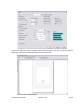
Move the mouse cursor to each Label Dimension field and enter the required dimensions to properly format for the print job at hand. Click on the FINISH button when complete and the following Label Gallery screen will appear with a blank label present. Click on DATA of the upper task bar and then select the RF DATA option. The following RF TAG screen will appear.
Click on the scoll-down arrow for the Type field and select the Alien - EPC (class 1) 64 bit menu option or the type of inlay desired. Next, click on the scoll-down arrow for the Data Type field and select either ASCII or Hex Encoded String option. ASCII Allows the data to be entered as full ASCII table and the software changes over to HEX when sending it to the printer. For a 64 bit tag selection, eight (8) digits must be used and for a 96 bit selection, twleve (12) digits must be used.
Click on the OK button when complete and the label will show up on the next screen with the RFID inlay outlined around the label. Refer to the screen below.
Populate the label with label fields. Refer to the Label Galley Manual’s Help Files for assistance as required. Once complete, click on FILE on the upper task bar, select the Print option and then enter the desired print quantity. The Print screen is displayed below.
EPC CODE WRITE DESIGNATION COMMAND FUNCTION Writes EPC code in RFID supply that supports EPC code. FORMAT IP0n.nnn PARAMETER n = Data to be written (16 bytes fixed for 64 bit inlays) or (24 bytes fixed for 96 bit inlays). EXAMPLE To write 64-bit EPC code “8000 0000 4000 0001” for label issuance in RFID supply that supports EPC code: A V50H50BD3020654912345678904 IP08000000040000001 Q1 Z NOTES Printing of multiple tags (QTY > 1) is available with this command.