Lt408 PRINT ENGINE OPERATOR MANUAL PN: 9001152A
SATO America, Inc. 10350A Nations Ford Road Charlotte, NC 28273 Main Phone: (704) 644.1650 Technical Support Hotline: (704) 644.1660 Technical Support Fax: (704) 644.1661 E-Mail: satosales@satoamerica.com technicalsupport@satoamerica.com www.satoamerica.com WARNING THE EQUIPMENT REFERENCED IN THIS DOCUMENT COMPLIES WITH THE REQUIREMENTS IN PART 15 OF FCC RULES FOR A CLASS B COMPUTING DEVICE. OPERATION OF THIS EQUIPMENT IN A RESIDENTIAL AREA MAY CAUSE UNACCEPTABLE INTERFERENCE TO RADIO AND TV RECEPTION.
TABLE OF CONTENTS INTRODUCTION About This Manual General Description Control Features 1-2 1-3 1-5 TECHNICAL DATA Physical Characteristics Power Enviromental Processing Command Interface Modules Regulatory Approvals Sensing Print Media Ribbon Character Font Capabilities Barcode Capabilities 2-2 2-2 2-2 2-2 2-2 2-2 2-2 2-3 2-3 2-3 2-3 2-4 2-5 INSTALLATION Unpacking & Parts Identification Printer Installation Site Location Installation Requirements Cable Connection Media Selection Ribbon Loading Media Load
PRINTER CONFIGURATION Printer Configuration Configuration Modes User Mode Advanced Mode Parallel Interface Setup Mode Serial Interface Setup Mode LAN Interface Setup Mode USB Interface Setup Mode Centronics Interface Setup Mode Service Mode Factory Mode Work Shift Mode Hidden Mode Download Mode Boot Download Mode Print Cancel Mode Default Settings Mode Test Print Mode Hex Dump Mode Menu Definition Tables 4-2 4-3 4-3 4-4 4-5 4-6 4-7 4-8 4-9 4-10 4-11 4-12 4-13 4-14 4-15 4-16 4-17 4-18 4-19 4-20 TROUBLESHOO
MAINTENANCE Cleaning Procedures Replacement Procedures Fuse Print Head Roller Adjustment Procedures Print Head Alignment Print Head Pressure Print Head Balance Ribbon Guide Label Sensor Positioning Operational Adjustments Volume Pitch Offset Darkness 6-2 6-3 6-3 6-3 6-4 6-5 6-5 6-6 6-7 6-8 6-9 6-10 6-10 6-10 6-10 6-10 APPENDIX Session Connect/Disconnect Ready/Busy Timing Charts X-On/X-Off Timing Charts Printer Dimensions Glossary Lt408 Operator Manual 7-2 7-3 7-4 7-5 7-7 PN: 9001152A
INTRODUCTION • • • Lt408 Operator Manual About This Manual General Description Control Features 1-1 PN: 9001152A
Unit 1: Introduction ABOUT THIS MANUAL This manual is laid out consistent with the product discussed and provides all of the information required for printer maintenance and repair by SATO approved personnel. For the repair technician, this manual is intended to compliment, and to be used as an extension of, owner/operator literature. This manual also incorporates the use of special information boxes. Examples of these boxes and the type of information provided in each, are below.
Unit 1: Introduction GENERAL DESCRIPTION The SATO Lt408, OEM print engine has been designed and manufactured to meet the needs of the entry-level print apply market. The entry-level market can be generally defined as small to mid-sized manufacturers with low throughput, light-duty applications. These applications do not require the feature set found on standard OEM print engines that usually make capital investment unjustifiable.
Unit 1: Introduction Cover Open Sensor Potentiometer Access Ribbon Rewind Spindle Ribbon Supply Spindle Ribbon Roller Print Head Latch Media Guide Front Platen Roller Feed Roller Dispenser Bar Pressure Plate Release Knob Print Head Release Knob Label Sensor Adjustment Knob Figure 1-1b, Primary Components Lt408 Operator Manual 1-4 PN: 9001152A
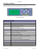
Unit 1: Introduction CONTROL FEATURES This chapter identifies the interactive control features of the printer. These functions are defined generally here. More specific explanations will be found throughout this manual on how to use them. FUNCTION LINE ENTER LCD DISPLAY FEED CANCEL Figure 1-2, Operator Panel OPERATOR PANEL FEATURES LED DEFINITION POWER Illuminates green when the printer is powered on. Terminates when powered off. ONLINE Illuminates green when the printer is in an online state.
TECHNICAL DATA • • • • • • • • • • • • Lt408 Operator Manual Physical Characteristics Power Enviromental Processing Print Media Ribbon Sensing Interface Modules Character Font Capabilities Barcode Capabilities Regulatory Approvals 2-1 PN: 9001152A
Unit 2: Technical Data PHYSICAL CHARACTERISTICS Width 12.99 Inches (330 mm) Height 10.63 Inches ( 270 mm) Depth 10.67 Inches ( 271 mm) Weight 21.38 Pounds (9.
Unit 2: Technical Data SENSING Gap Adjustable Reflective Eye-Mark Adjustable Ribbon Near End Enable/Disable Media Out Constant Cover Open Constant PRINT Method Maximum Speed (selectable) Direct Thermal / Thermal Transfer 2, 3, 4, 5, 6 Inches Per Second (50.8-152.4 mm) Print Module (dot size) .0049 Inches (.125 mm) Resolution 203 Dots Per Inch (8 dpmm) Maximum Print Width 4.10 Inches (104 mm) Maximum Print Length 49.17 Inches (1249 mm) MEDIA Width Media Width: 1.00 to 4.41 Inches (25.
Unit 2: Technical Data CHARACTER FONT CAPABILITIES MATRIX FONTS XU 5 dots W x 9 dots H (Helvetica) XS 17 dots W x 17 dots H (Univers Condensed Bold) XM 24 dots W x 24 dots H (Univers Condensed Bold) OA Font (OCR-A) 15 dots W x 22 dots H OB Font (OCR-B) 20 dots W x 24 dots H AUTO SMOOTHING FONTS XB 48 dots W x 48 dots H (Univers Condensed Bold) XL 48 dots W x 48 dots H (Sans Serif) VECTOR FONT Proportional or Fixed Spacing Font Size 50 x 50 dots to 999 x 999 dots Helvetica, 10 Font Variations
Unit 2: Technical Data BAR CODE CAPABILTIES Linear Bar Codes UPC A/E JAN 8/13 EAN 8/13 Code 39 Code 93 Code 128 Interleaved 2 of 5 Industrial 2 of 5 Matrix 2 of 5 Bookland RSS-14 MSI POSTNET UCC/EAN 128 NW-7 (Codabar) Two Dimemsional QR Code Data Matrix Maxi Code PDF417 Synthetic Symbol Ratios Bar Height 1:2, 1:3, 2:5, User definable bar widths 4 to 999 dots, User progammable Rotation Sequential Numbering Expansion Ratio of Character Graphics Form Overlay Lt408 Operator Manual 0, 90, 180, and 270
INSTALLATION • • • • • Lt408 Operator Manual Unpacking & Parts Identification Printer Installation Operational Mode Selection Interface Selection Accessories Installation 3-1 PN: 9001152A
Unit 3: Installation UNPACKING & PARTS IDENTIFICATION Unpack the printer as directed in the folowing procedure. 1. Place the shipping container (box) upright on a stable, flat surface. 2. Open the box, remove any loose items and the first layer of packing material. 3. Carefully lift the printer and accessories from the box and place them on a stable, flat surface. 4. Remove the plastic covers from the packed items and visually inspect for physical damage. 5.
Unit 3: Installation PRINTER INSTALLATION This chapter provides guidance on how to station, connect, and load the printer once unpacked. Following printer setup, proceded to the next chapter for information on interface selection. SITE LOCATION • Stationed away from hazardous materials. • Stationed within an enclosed structure that conforms to the printer’s enviromental requirements. • Stationed within operational distance of the host based on interface specifications.
Unit 3: Installation Figure 3-3, Printer Mounting Host Computer Breaker Box Applicator Power Cord OR Interface Cable EXT Interface Printer Interface Card Figure 3-4, Printer Connection ATTENTION: Figure 3-4 displays the printer interfaced with a host computer. However, the printer may also be interfaced with a PLC, keyboard, scanner, etc.
Unit 3: Installation MEDIA SELECTION The size and type of labels to be printed should have been taken into consideration before printer purchase. Ideally, the media width will be equal to, or just narrower than, the print head. Using media that does not cover the print head will allow the platen roller to tread upon its surface resulting in premature wear. The media edge will also wear a groove in the platen roller affecting print quality.
Unit 3: Installation MEDIA LOADING To load label media, unlatch the print head and remove any remnants that may exist of the prior media supply. Feed the free end of the media from the printer’s left side, beneath the shaft of the media guide, between the upper and lower halves of the label sensor, across the top of all forthcoming rollers, and through to protrude six or more inches beyond the printer chassis.
Unit 3: Installation OPERATIONAL MODE SELECTION There are two modes of printer operation: Dispense or Continuous. The difference between the two is the way that the label and paper backing is ejected. Before printer configuration, one must determine which mode will be used. This chapter identifies and defines the functional differences between the two.
Unit 3: Installation INTERFACE SELECTION This unit presents the printer interface types and their specifications. These specifications include detailed information to assist in the selection of the most appropriate method for the printer to interface with the host. The five acceptable interface methods are: • RS232C High-Speed Serial • IEEE1284 Parallel • Universal Serial Bus (USB) • Local Area network (LAN) Ethernet • 802.
Unit 3: Installation RS232C HIGH-SPEED SERIAL INTERFACE INTERFACE SPECIFICATIONS Asynchronous ASCII Half-duplex communication Bi-Directional Communication Data Transmission Rate 9600, 19200, 38400, 57600 bps Transmission Form Start, b1, b2, b3, b4, b5, b6, b7, b8, Stop (b8 will be omitted if using 7 bit oriented) Data Length 7 or 8 bit (selectable) Stop Bit 1 or 2 bit (selectable) Parity Bit ODD, EVEN, NONE (selectable) Codes Used ASC II Character Codes: 7 bits, Graphics: 8 bits Control Codes
Unit 3: Installation READY/BUSY INTERFACE SIGNALS PIN DIRECTION SIGNAL DEFINITION 1 Reference FG (Frame Ground) 2 To Host TD (Transmit Data) - Data from the printer to the host computer. Sends X-On/X-Off characters or status data (bi-directional protocols). 3 To Printer RD (Receive Data) - Data to the printer from the host computer. 4 To Host RTS (Request to Send) - Used with Ready/Busy flow control to indicate an error condition.
Unit 3: Installation IEEE1284 PARALLEL INTERFACE The parallel interface is a plug-in module that can be installed by the user and conforms to IEEE1284 specifications. It automatically detects the IEEE1284 signals and operates in the high speed mode. If the IEEE1284 signals are not detected, it will operate in the slower standard Centronics mode. For this reason, an interface cable and host interface conforming to the IEEE1284 specification must be present to fully utilize the speed capabilities.
Unit 3: Installation UNIVERSAL SERIAL BUS (USB) The Universal Serial Bus (USB) interface is a Plug-In Interface Module that can be installed by the user. It requires a driver (shipped with each printer that has the interface installed) that must be loaded onto the PC and configured to support USB peripherals using Windows 2000 or above. Details for loading the USB driver are contained in the USB Interface Manual that is shipped with each printer with a USB Optional interface installed.
Unit 3: Installation SOFTWARE SPECIFICATIONS Corresponding Protocol TCP/IP Network Layer ARP, RARP, IP, ICMP Session Layer TCP, UDP Application Layer LPD, FTP, TELNET, BOOTP, DHCP NOTE: Print data can be sent by LPR and FTP of TCP/IP and dedicated socket protocol. Printer status is obtainable by dedicated socket protocol. NOTE: In the TCP/IP protocol enviroment, LPD and FTP are provided for printing; TELNET for variable setup; ARP, RARP, and BOOTP/DHCP for address setup.
Unit 3: Installation DIPSWITCH SETTINGS The dipswitches serve to initialize the configuration saved on the Wireless-LAN board, print the configuration, and make a selfdiagnosis. To communicate with the host,set the communication mode by through switches 5 and 6, then set the remaining switches to the OFF position. Print of configuration and self-diagnsis are operable only on the screen after turning on the printer. Ensure all switches are in the OFF position when operating the printer.
Unit 3: Installation Figure 3-10, Socket Connection Diagram Lt408 Operator Manual 3-15 PN: 9001152A
Unit 3: Installation ALL INTERFACES RECEIVE BUFFER The data stream is received from the host to the printer one job at a time. This allows the software program to maintain control of the job print queue so that it can move a high priority job in front of ones of lesser importance. A multiple job buffer allows the printer to continuously receive print jobs while compiling and printing other jobs at the same time. It acts much like a Print buffer to maximize the performance of the host and the printer.
Unit 3: Installation RECEIVE BUFFER CONTROL Causes For Receive Buffer Near Full Receive buffer near full occurs when the remaing free space of the buffer drops to 0.95MB of 2.95MB capacity or when the remaining free space is available for storing 50 of 500 items in the history buffer. Release Of Receive Buffer Near Full Receive buffer near full can be released when the remaining free space rises to 1.95MB or when the remaining free space is available for storing 200 items in the history buffer.
Unit 3: Installation STATUS5 TIMING CHARTS PRINT PROCESS (Figure 3-11d) COMMAND PROCESS (Figure 3-11e) BCC ERROR PROCESS (Figure 3-11f) Lt408 Operator Manual 3-18 PN: 9001152A
Unit 3: Installation EXTERNAL SIGNAL The external signal interface is designed to connect the printer to an applicator. Proceed to the printer’s Advanced Mode for various setup activities related to the external signal. There are two connector types available for the external signal interface, one with a 14-pin connector and the other with a 25-pin connector. SPECIFICATIONS Signal Level High: +2.4 to +5.0V, Low: +0.0 to +0.4V Issuing/Reissuing EXT signal Enable/Disable in the Advanced Mode.
Unit 3: Installation Figure 3-12, Input/Output Circuit Diagram Figure 3-13, 14-Pin Connector Assignments INPUT SIGNAL WAVE FORM START PRINTING (Figure 3-14a) REPRINTING (Figure 3-14b) Lt408 Operator Manual 3-20 PN: 9001152A
Unit 3: Installation OUTPUT SIGNAL WAVE FORM BASIC OPERATION (Figure 3-15a) PAPER END (Figure 3-15b) RIBBON END (Figure 3-15c) MACHINE ERROR (Figure 3-15d) Lt408 Operator Manual 3-21 PN: 9001152A
Unit 3: Installation Figure 3-16, Operation Mode Flow Chart Lt408 Operator Manual 3-22 PN: 9001152A
Unit 3: Installation ACCESSORIES INSTALLATION This unit covers all of printer accessory installation procedures. INTERFACE INSTALLATION The diagram below displays the physical installation of interface hardware. The interface type chosen determines the applicable slot in the printer for installation.
PRINTER CONFIGURATION • • • Lt408 Operator Manual Printer Configuration Configuration Modes Menu Definition Tables 4-1 PN: 9001152A
Unit 4: Printer Configuration PRINTER CONFIGURATION This unit provides in-depth instruction on printer configuration for operation and for some troubleshooting. The printer may be configured via the buttons and/or potentiometers located on the printer’s operator panel. All of the printer’s buttons, switches, and potentiometers are used either singularly, or in conjunction, to perform configuration activities.
Unit 4: Printer Configuration CONFIGURATION MODES This chapter provides an overview of the various configuration modes of the operation menu. All of the configuration activities are performed via the use of the operator panel located on the printer’s face. However, many settings may also be controlled via external software commands. In the case of conflict between external software commands and internal software commands (control panel settings) the printer will always use the last valid setting.
Unit 4: Printer Configuration ADVANCED MODE The Advanced Mode is provided to make basic printer operational adjustments. Typically, once these adjustments or settings have been made, they will not require additional address unless a new job is downloaded. Use the keys of the printer’s operator panel to select and enter the required options. Refer to the Menu Definition Tables in the following chapter to provide an explanation of each menu screen.
Unit 4: Printer Configuration PARALLEL INTERFACE SETUP MODE This chapter provides the programming sequences required for IEEE1284 interface setup. Use the keys of the printer’s operator panel and enter the required options. Refer to the Menu Definition Tables in the following chapter to provide an explanation of each menu screen. ATTENTION: Do not perform the following programming sequence if this is not the interface type to be used. Instead, refer to the appropriate interface programming flow chart.
Unit 4: Printer Configuration SERIAL INTERFACE SETUP MODE This chapter provides the programming sequences required for RS232C, RS422, or RS485 interface setup. Use the key of the printer’s operator panel to select and enter the required options. Refer to the Menu Definition Tables in the following chapter to provide an explanation of each menu screen. ATTENTION: Do not perform the following programming sequence if this is not the interface type to be used.
Unit 4: Printer Configuration LOCAL AREA NETWORK (LAN) INTERFACE SETUP MODE This chapter provides the programming sequences required for LAN, Wireless LAN, and Mini-LAN interface setup. Use the keys of the printer’s operator panel to select and enter the required options. Refer to the Menu Definition Tables in the following chapter to provide an explanation of each menu screen. ATTENTION: Do not perform the following programming sequence if this is not the interface type to be used.
Unit 4: Printer Configuration USB INTERFACE SETUP MODE This chapter provides the programming sequences required for USB interface setup. Use the keys of the printer’s operator panel to select and enter the required options. Refer to the Menu Definition Tables in the following chapter to provide an explanation of each menu screen. ATTENTION: Do not perform the following programming sequence if this is not the interface type to be used. Instead, refer to the appropriate interface programming flow chart.
Unit 4: Printer Configuration CENTRONICS INTERFACE SETUP MODE This chapter provides the programming sequences required for Centronics interface setup. Use the keys of the printer’s operator panel to select and enter the required options. Refer to the Menu Definition Tables in the following chapter to provide an explanation of each menu screen. ATTENTION: Do not perform the following programming sequence if this is not the interface type to be used.
Unit 4: Printer Configuration SERVICE MODE Allows the programming of various dimensional settings, sensor thresholds, and language options. Use the keys of the printer’s operator panel to select and enter the required options. Refer to the Menu Definition Tables in the following chapter to provide an explanation of each menu screen.
Unit 4: Printer Configuration FACTORY MODE The Factory Mode permits counter reset of various printer components. Use the keys of the printer’s operator panel to select and reset those features. Refer to the Menu Definition Tables in the following chapter to provide an explanation of each menu screen.
Unit 4: Printer Configuration WORK SHIFT MODE The Work Shift mode allows for specific production information regarding printing activity on a given work shift to be recorded. Use the keys of the printer’s operator panel to select and enter the required options. Refer to the Menu Definition Tables in the following chapter to provide an explanation of each menu screen. The Y E S option m ust have been selected for the S hift C ode w ithin the H idden M ode m enu .
Unit 4: Printer Configuration HIDDEN MODE Use the keys of the printer’s operator panel to select and enter the required options. Refer to the Menu Definition Tables in the following chapter to provide an explanation of each menu screen.
Unit 4: Printer Configuration DOWNLOAD MODE This download feature allows the operator to downgrade or upgrade Firmware to the printer. When downloading is complete, the LCD screen will return to the original display. If an error occurs, a DOWNLOAD ERROR will display. Use the keys of the printer’s operator panel to select and enter the required options. Refer to the Menu Definition Tables in the following chapter to provide an explanation of each menu screen.
Unit 4: Printer Configuration BOOT DOWNLOAD MODE This download mode is used when the Firmware becomes corrupted and the normal download mode is not successful. Figure 5-13 provides the specific sequence of events required by the operator, the printer, and the printer’s software for downloading Firmware to the printer. Use the key of the printer’s operator panel to select and enter the required options.
Unit 4: Printer Configuration PRINT CANCEL MODE Figure 5-14 provides the specific sequence of events required by the operator, the printer, and the printer’s software to cancel a print job once initiated. Use the keys of the printer’s operator panel to select and enter the required options. Refer to the Menu Definition Tables in the following chapter to provide an explanation of each menu screen. Printing in process.
Unit 4: Printer Configuration DEFAULT SETTING MODE Figure 5-15 provides the specific sequence of events required by the operator, the printer, and the printer’s software to return the printer to the configuration state as received from the factory. Use the keys on the printer’s operator panel to select and enter the required options. Refer to the Menu Definition Tables in the following chapter to provide an explanation of each menu screen.
Unit 4: Printer Configuration TEST PRINT MODE Figure 5-16 provides the specific sequence of events required by the operator, the printer, and the printer’s software for a test label to be printed. Test labels are designed to identify failures in configuration, adjustment problems, and mechanical defects. Use the key on the printer’s operator panel to select and enter the required options. Refer to the Menu Definition Tables in the following chapter to provide an explanation of each menu screen.
Unit 4: Printer Configuration HEX DUMP MODE The contents of the print buffer and the data received before it is placed into the print buffer may be examined through the use of the Hex Dump Mode. Each line of the printed data is enumerated in the first column, the second column contains the data in hexadecimal format, and the right column contains the same data in ASCII format. The options of data to be printed are: receive data, receive buffer, and internal data.
Unit 4: Printer Configuration MENU DEFINITION TABLES USER MODE (TABLE 4-1) MENU ONLINE QTY: 000000 DESCRIPTION Displays the operational status of the printer. The ONLINE status is displayed on the top line and the label quantity status on the bottom. The message will be changed to OFFLINE whenever the printer is switched offline by pressing the LINE key. When a print job is received, the quantity line will indicate the number of labels to be printed.
Unit 4: Printer Configuration USER MODE (TABLE 4-1) MENU DESCRIPTION PRINT OFFSET V: +XXXX H: +XXXX This menu allows for the printer to be configured to print zeros with or without a diagonal slash through them. This will apply to all printer resident font types. ZERO SLASH YES Print offset refers to the vertical and horizontal shifting of the entire print area relative to the label and the print start position. The movement is incremented by dots in the positive (+) or negative (-) direction.
Unit 4: Printer Configuration ADVANCED MODE (TABLE 4-2) MENU DESCRIPTION Allows the choice of continuous feed or dispenser operation. PRINTER TYPE DISPENSER CONTINUOUS BACKFEED MOTION Allows the determination of whether a backfeed motion will be applied. If so, the selection of before or after the printing of each label. BEFORE NONE AFTER Allows the printer to be switched to operate in the thermal transfer or direct thermal mode as desired.
Unit 4: Printer Configuration ADVANCED MODE (TABLE 4-2) MENU DESCRIPTION EXTERNAL REPRINT ENABLE DISABLE The printer can be set to automatically go into the online mode when powered on. Otherwise, the printer starts in the offline state and must be manually placed online before it is ready to print. AUTO ONLINE YES Allows configuration as to whether the reprint function may be activated via the external signal port. NO This feature allows one label to be fed upon the printer entering online mode.
Unit 4: Printer Configuration PARALLEL INTERFACE MODE (TABLE 4-3) MENU Is a transitional screen that allows the operator to choose a given direction within the menu map. ONLINE MODE INTERFACE MODE INTERFACE BOARD SETTING YES Is the premier screen of the Interface Mode. The Interface Mode allows the parameters to be set for the printer to communicate with a host and vise-versa. Select the YES option if an interface board for bi-directional communication will be configured.
Unit 4: Printer Configuration PARALLEL INTERFACE MODE (TABLE 4-3) MENU IGNORE CAN/DLE YES DESCRIPTION Allows 1-byte command such as CAN and DLE code to be deleted. Will only appear when the communication protocol is STATUS4. NO SERIAL INTERFACE MODE (TABLE 4-4) MENU ONLINE QTY: 000000 DESCRIPTION Displays the operational status of the printer. The ONLINE status is displayed on the top line and the label quantity status on the bottom.
Unit 4: Printer Configuration SERIAL INTERFACE MODE (TABLE 4-4) MENU DESCRIPTION RECEIVE BUFFER MULTI Allows the selection of the receive buffer type. Select MULTI for multi-item buffer and 1ITEM for a single item buffer. 1 ITEM Allows selection of the baud rate. Will only appear when the RS232C interface is installed and the LCD option is chosen from the prior menu. BAUDRATE 2400 9600 4800 19200 Allows setting of the parity bit for the serial interface.
Unit 4: Printer Configuration LAN INTERFACE MODE (TABLE 4-5) MENU ONLINE QTY: 000000 DESCRIPTION Displays the operational status of the printer. The ONLINE status is displayed on the top line and the label quantity status on the bottom. The message will be changed to OFFLINE whenever the printer is switched offline by pressing the LINE key. When a print job is received, the quantity line will indicate the number of labels to be printed.
Unit 4: Printer Configuration LAN INTERFACE MODE (TABLE 4-5) MENU DESCRIPTION Specifies which segment of the network the printer will reside. The format of Subnet Mask is a 32-bit numeric address written as four numbers separated by periods. See your Network Administrator to find out your Subnet Mask. SUBNET MASK 0. 0. 0. 0 Specifies the IP Address of the main router on the host network. The format of a Gateway Address is a 32-bit numberic address written as four numbers separated by periods.
Unit 4: Printer Configuration USB INTERFACE MODE (TABLE 4-6) MENU DESCRIPTION Is a transitional screen that allows the operator to choose a given direction within the menu map. ONLINE MODE INTERFACE MODE Is the premier screen of the Interface Mode. The Interface Mode allows the parameters to be set for the printer to communicate with a host and vise-versa. Select the YES option if an interface board for bi-directional communication will be configured.
Unit 4: Printer Configuration CENTRONICS INTERFACE MODE (TABLE 4-7) MENU ONLINE QTY: 000000 DESCRIPTION Displays the operational status of the printer. The ONLINE status is displayed on the top line and the label quantity status on the bottom. The message will be changed to OFFLINE whenever the printer is switched offline by pressing the LINE key. When a print job is received, the quantity line will indicate the number of labels to be printed.
Unit 4: Printer Configuration SERVICE MODE (TABLE 4-8) MENU DESCRIPTION MAINTENANCE MODE SERVICE MODE FACTORY MODE The Maintenance Mode is divided into two sections; the Service Mode and the Factory Mode. The Service Mode allows the programming of various dimensional settings, sensor thresholds, and language options. The Factory Mode permits counter reset of various printer components. Use the printer’s operator panel to select and reset those features.
Unit 4: Printer Configuration SERVICE MODE (TABLE 4-8) MENU DESCRIPTION Allows the option of reprinting a label with key or not. FUNCTION KEY NONE REPRINT FORWARD / BACKFEED DISTANCE DEFAULT XXX MM WEB ACCELERATION FAST Allows selection of output mode options. MODE1 outputs signal in the status of existence/non-existence for the number of remaining labels to be printed. MODE2 outputs signal in the status of online/offline.
Unit 4: Printer Configuration SERVICE MODE (TABLE 4-8) MENU DESCRIPTION When enabled (ON), the printer’s status (receiving, editing, printing) will be displayed as an icon. Disabled (OFF) conversely, does not. TRACE MODE ON OFF FACTORY MODE (TABLE 4-9) MENU DESCRIPTION MAINTENANCE MODE SERVICE MODE FACTORY MODE The Maintenance Mode is divided into two sections; the Service Mode and the Factory Mode. The Factory Mode permits counter reset of various printer components.
Unit 4: Printer Configuration FACTORY MODE (TABLE 4-9) MENU DESCRIPTION This printer does not have a dispenser assembly, thusly this screen should be ignored. DISPENSE COUNTER X.X M Enables the printer’s serial number to be recorded within its memory. SERIAL NO. S/N XXXXXXXX Enables the revision number of the main circuit board to be recorded within its memory. MAIN PCB REVISION REV X.X Enables the revision number of the interface board to be recorded within its memory. INTERFACE BOARD REVISION REV X.
Unit 4: Printer Configuration WORK SHIFT MODE (TABLE 4-10) MENU ONLINE QTY: 000000 2 3 Displays the operational status of the printer. The ONLINE status is displayed on the top line and the label quantity status on the bottom. The message will be changed to OFFLINE whenever the printer is switched offline by pressing the LINE key. When a print job is received, the quantity line will indicate the number of labels to be printed.
Unit 4: Printer Configuration DOWNLOAD MODE (TABLE 4-12) MENU DESCRIPTION Confirms the printer is on standby for receiving the downgrade or upgrade of Firmware from the host. DOWNLOAD WAITING Downloading progress may be monitored here. Entry is not required at this screen. Press the CANCEL key located on the operator panel to abort downloading. DOWNLOADING Displays when the download process is complete. Press the ENTER key located on the operator panel to exit.
Unit 4: Printer Configuration PRINT CANCEL MODE (TABLE 4-14) MENU DESCRIPTION Displays the operational status of the printer. The OFFLINE status is displayed on the top line and the label quantity status on the bottom. The message will be changed to ONLINE whenever the printer is switched online by pressing the LINE key. OFFLINE QTY: 000000 Print data that has been previously received, can be cleared. If YES is selected, the print data will be deleted and then the printer will go offline.
Unit 4: Printer Configuration TEST PRINT MODE (TABLE 4-16) MENU DESCRIPTION Is the initial screen of the Test Print Mode. TEST PRINT MODE CONFIGURATION BARCODE HEAD CHECK FONT FACTORY TEST PRINT SIZE • Configuration: The printer’s configuration settings. • Barcode: The printer’s installed barcodes. • Head Check: A pattern to check print head elements. • Font: The contents of the installed fonts. • Factory: A factory test label will be printed.
Unit 4: Printer Configuration HEX DUMP MODE (TABLE 4-17) MENU DESCRIPTION The Advanced Mode screen is only a transitional screen to the Hex Dump Mode screen. ADVANCED MODE HEX DUMP MODE Is the premiere screen to the Hex Dump Mode. The contents of the print buffer and the data received before it is placed into the print buffer may be examined through the use of the Hex Dump Mode.
TROUBLESHOOTING • • • • • Lt408 Operator Manual Error Signal Troubleshooting Warning Signal Troubleshooting Troubleshooting Table Interface Troubleshooting Test Print Modes 5-1 PN: 9001152A
Unit 5: Troubleshooting ERROR SIGNAL TROUBLESHOOTING This chapter identifies the printer’s various LCD error signals and their relative audible alarms, as well as, their probable causes and remedies for problem resolution.
Unit 5: Troubleshooting ERROR DISPLAYS LED CONDITION ERROR 09 Ribbon End Error POWER: ONLINE: LABEL: RIBBON: On Off Off On 10 Sensor Error POWER: ONLINE: LABEL: RIBBON: On Off Off Off 11 Head Related Error POWER: ONLINE: LABEL: RIBBON: On Off Off Off 17 Memory Reading Error POWER: ONLINE: LABEL: RIBBON: On Off Off Off 18 Item Number Error POWER: ONLINE: LABEL: RIBBON: On Off Off Off 20 Head Mismatch Error POWER: ONLINE: LABEL: RIBBON: On Off Off Off 25 Cover Open Error POWER: ONLINE: LA
Unit 5: Troubleshooting ERROR ICONS LCD ICONS DESCRIPTION OF ERROR Displayed when detecting Label End. POSITION ON LCD Icon 1 Displayed when detecting Ribbon End. Icon 1 Displayed when detecting Sensor Error. Icon 1 Displayed when detecting Head Open. Icon 1 Displayed when head is disconnected. Icon 1 Displayed when detecting Communication Error. Displayed when detecting Receive Buffer Over. Icon 1 Icon 1 Displayed when detecting Item No. Error or BCC Error.
Unit 5: Troubleshooting WARNING SIGNAL TROUBLESHOOTING WARNING DISPLAYS LED CONDITION WARNING 01 Ribbon Near-End Warning POWER: ONLINE: LABEL: RIBBON: On On On Off 03 Receive Buffer Near-Full Warning POWER: ONLINE: LABEL: RIBBON: On On Off Off 04 Command Error Warning POWER: ONLINE: LABEL: RIBBON: On On Off Off 05 Head Error Warning POWER: ONLINE: LABEL: RIBBON: On On Off Off DESCRIPTION LCD DISPLAY 1. Limited media quantity remaining. 2. Monitor and reload before all is used.
Unit 5: Troubleshooting TROUBLESHOOTING TABLE TROUBLESHOOTING TABLE IMAGE VOIDS Dirty print head. Clean print head. Damaged print head. Replace print head. Damaged electronics. Replace circuit board. Damaged or worn roller. Replace rollers. Poor label quality. Use higher quality media. Ribbon stock and media are mismatched. Consult with media supplier. RIBBON WRINKLING Poor head alignment. Adjust head balance and alignment. Excessive temperature setting Adjust temperature.
Unit 5: Troubleshooting NO PRINTED IMAGE Print head is disconnected. Ensure print head wiring harness is connected on each end. No voltage output. Replace fuse. Test power supply and replace as required. Defective print head. Replace print head and reset counter. Damaged electronics. Replace circuit board. Interface problems. Troubleshoot interface - refer to the next chapter. Data input error. Ensure correct data stream. PRINTER CREATES A BLANK LABEL. Data input error.
Unit 5: Troubleshooting INTERFACE TROUBLESHOOTING This chapter provides a checklist for the various interface types. Locate the checklist relative to the interface used and perform each of the troubleshooting tasks until the problem has been isolated. PARALLEL INTERFACE CHK TROUBLESHOOTING STEP Ensure the interface module is correctly installed. Run self-test to verify. Ensure the printer cable is connected to the appropriate LPT port on the host computer.
Unit 5: Troubleshooting LAN ETHERNET INTERFACE CHK TROUBLESHOOTING STEP Ensure the interface has been correctly configured. Wait two minutes and run self-test to verify. If a test label does not print, there may be a hardware problem. Ensure the cable and its ports are not defective. Ensure that a faulty print server or other protocol related scenarios are not creating a queue setup issue. Systematically perform checks and tests to isolate the cause.
Unit 5: Troubleshooting TEST PRINT TROUBLESHOOTING Chapter provides instruction on special printing to identify and resolve specific print problems. HEX DUMP Allows the operator to determine if there were problems in the downloading of data. TEST LABEL Allows the operator to identify specific problems regarding mechanical performance and setup. HEX DUMP MODE The contents of the print buffer can be examined using the Hex Dump Mode. In the left column, each line of data received is numbered.
Unit 5: Troubleshooting TEST LABEL PRINTING The test label is designed to assist in the identification of print problems. Follow the flow chart provided below to perform this activity.
Unit 5: Troubleshooting NOTE: The only print problem that the following sample test label does not display is fading of print image from one side of the label to the other. This is the result of improper print head balance. Compare this scale on each side to ensure the print is evenly spaced horizontally . Visually inspect these rows for voids indicating defective head elements. SAMPLE TEST LABEL Label Contents Will Vary Depending on Test Label Type .
MAINTENANCE • • • Lt408 Operator Manual Cleaning Procedures Replacement Procedures Adjustment Procedures 6-1 PN: 9001152A
Unit 6: Maintenance CLEANING PROCEDURES Cleaning of the printer is a necessary maintenace activity to ensure print quality and longer printer life. There are two basic types of cleaning involved; the removal of loose debris and the removal of residue. Use a soft cloth and/or a pneumatic blower to remove debris from the printer. This process should be performed prior to the removal of residue.
Unit 6: Maintenance REPLACEMENT PROCEDURES This unit provides in-depth instruction on all primary component and assembly replacement, in addition to most secondary components. Use the text in conjunction with their accompanied graphics to ensure complete comprehension throughout the process. Especially observe all cautionary or warning notations. FUSE REPLACEMENT Fuse access may be gained externally without having to remove covers, etc.
Unit 6: Maintenance ROLLER REPLACEMENT The printer’s three rubber rollers are considered to be high-wear components due to constant treading of the print media and ribbon stock against their contact surfaces. This constant contact will eventually wear grooves into the rubber material and negatively effect print output. The procedure below applies for all three rubber rollers. However, some rollers do not incorporate the use of spacer (5) so in those cases, that process is to be ignored. 1.
Unit 6: Maintenance ADJUSTMENT PROCEDURES This unit covers all of the printer and printer accessory adjustments. These adjustments include mechanical adjustments required following the replacement of components and assemblies, in addition to, the operational adjustments required following a job change. PRINT HEAD ALIGNMENT Print head position has a direct impact on print quality. The print head must be parallel with the platen roller for the printed image to be consistent across the label.
Unit 6: Maintenance PRINT HEAD PRESSURE ADJUSTMENT Print head pressure adjustment allows for the print head to be adjusted to accommodate different media types (thicknesses). The pressure setting switch is two position (normal, high). The table that follows correlates the media used with a pressure setting. PRESSURE/BALANCE ADJUSTMENT Paper Width (inches) Dial Setting 2.17+ 0.612 to 2.16 2.56+ 0.62 to 2.55 1 2 3 4 PRESSURE REQUIREMENTS Paper Thickness (inches) 0.003 to 0.008 0.008 to 0.
Unit 6: Maintenance PRINT HEAD BALANCE ADJUSTMENT Print head balance is the equalization of pressure against the platen roller from one end to the opposite. If the print head balance is out of adjustment, the printed image will be darker on one side of the label than the other and the media will be prone to travel in the direction of least resistance. The adjustment of print head balance on the label can be subjective.
Unit 6: Maintenance RIBBON GUIDE ADJUSTMENT If the print ribbon is not spread smoothly over the print head when it makes contact with the media, print voids will occur at the point of the ribbon fold. Typically, this is the result of the axis of one of the following not being perfectly parallel: ribbon spindle, ribbon roller, print head, or ribbon guide. The purpose of the adjustable ribbon guide is to compensate for the axis deviations of the other three.
Unit 6: Maintenance LABEL SENSOR POSITIONING The label sensor assembly provides a mounting apparatus for the eye-mark, gap, and paper-end sensors. Position adjustment of the label sensor is not required when using standard label media. When non-standard media is used, place a section of the media on the media ramp oriented as if loaded for printing. Manually grasp the sensor assembly and move it laterally so that the sensor indicators embossed in its side are aligned with the reference marks on the media.
Unit 6: Maintenance OPERATIONAL ADJUSTMENTS These operational adjustments are for fine tuning the printer as necessary following the configuration process and are largely confined to the four potentiometers located on the operator panel. Refer to the table below for their function. POTENTIOMETER DESCRIPTION/PROCEDURE VOLUME Adjusts the audible decimal level for error indication. Power on the printer, place on-line, and open the print head. When the beep is emitted, adjust the volume level accordingly.
APPENDIX • • • • • Lt408 Operator Manual Session Connect/Disconnect Diagram Ready/Busy Timing Charts X-On/X-Off Timing Charts Printer Dimensions Glossary 7-1 PN: 9001152A
Unit 7: Appendix SESSION CONNECT/DISCONNECT DIAGRAM Figure 7-1, Session Connect/Disconnect Diagram Lt408 Operator Manual 7-2 PN: 9001152A
Unit 7: Appendix READY/BUSY TIMING CHARTS Figure 7-2a, Single-Item Buffer Timing Charts Figure 7-2b, Multiple-Item Buffer Timing Charts Lt408 Operator Manual 7-3 PN: 9001152A
Unit 7: Appendix X-ON/X-OFF TIMING CHARTS Figure 7-3a, Single-Item Buffer Timing Charts Figure 7-3b, Multiple-Item Buffer Timing Charts Lt408 Operator Manual 7-4 PN: 9001152A
Unit 7: Appendix PRINTER DIMENSIONS Figure 7-4a, Front View Figure 7-4b, Interface Side Lt408 Operator Manual 7-5 PN: 9001152A
Unit 7: Appendix Figure7-4c, Back View Lt408 Operator Manual 7-6 PN: 9001152A
Unit 7: Appendix GLOSSARY GLOSSARY AC (Alternating Current) Electrical current that reverses its direction regularly and continually. Accessory An optional assembly that may be used to provide an additional function. Active Tags RFID tags which use batteries as partial or complete source of power which are further differentiated by separating them into those with replaceable batteries and those which have the batteries inside a sealed unit. Also referred to as Utilized Active Tags.
Unit 7: Appendix GLOSSARY Bytes A collection of 8 bits used in the binary system. Capacity As it relates to RFID, the number of bits or bytes that can be programmed into a tag. This may represent the bits accessible to the user or the total number - including those reserved to the manufacturer (e.g., parity or control bits). Capture Window/Field Region of the scanner field in which an RFID tag will operate. Cavity A recessed area in something.
Unit 7: Appendix GLOSSARY Diode Allows current to flow in one direction but not the other to protect sensitive electronics. A diode functions by compositing two conductive materials with one possessing low resistance to electrical current on one side and high resistance on the other. Dipswitch Complex A group of tiny switches directly attached to a circuit board to enable configuration for a particular type of application. These switches are two-position: On/Off.
Unit 7: Appendix GLOSSARY Factory Programming Relative to RFID, the programming of information into a tag occurring as part of the manufacturing process resulting in a read-only tag. Field Programming In RFID, programming that usually occurs before the tag is installed on the object to be identified enabling the introduction of data relevant to the specifics of the application. However, the tag would typically have to be removed from its object.
Unit 7: Appendix GLOSSARY Key The button on a panel that may be pressed to send an electrical signal to influence a predetermined activity. Keyed A physical object shaped in a manner so as to prevent unwanted movement or to ensure desired movement. Kg (Kilogram) A unit of weight measure within the metric system. Kilo-Bytes Used to describe data transfer rates or storage capacity of approximately 1000 bytes.
Unit 7: Appendix GLOSSARY Modulation In RFID, the methods of altering carriers in order to transmit the encoded information. Nest A set of similarly shaped objects with one smaller and resting within the other. Nominal The point between a positive and negative deviation which is considered to be optimum. Nut A small metal block with a threaded hole through its center for screwing onto a bolt.
Unit 7: Appendix GLOSSARY Print Head The device on a direct thermal or thermal transfer printer containing the heating elements that causes an image to be transferred to print media. Processor A programmable device that performs all the instruction, logic, and mathematical processing in a computer - is the brains of the computer. The processor is a microchip that is installed on a motherboard (primary board) that coordinates hardware components. Also referred to as “CPU”.
Unit 7: Appendix GLOSSARY A system of finding the position or location of assets. RFID Tags A microchip attached to an antenna that is packaged in a way that it can be applied to an object. The tag picks up signals from, and sends signals to, a reader. The tag contains a unique serial number, but may have other information and come in many forms, such as smart labels that can have a barcode printed on it, or can simply be mounted inside a carton or embedded in plastic.
Unit 7: Appendix GLOSSARY Simultaneous To take place at the same time. Sleeve A thin hollow material that is inserted onto another to provide proportionate spacing. Snap Ring A circular clip that may be applied to a shaft, etc. to prevent another object from moving - used to retain objects in position. Solid An item that is not porous. An item that is not transparent or translucent. Spacer Any object of purpose to maintain a specific distance from two other objects - example: a sleeve or washer.
Unit 7: Appendix GLOSSARY Troubleshoot The act of locating the source of a problem or problems. Two-Dimensional Two of the projectories of an object: X axis is the distance left and right and the Y axis is the distance up and down. In a two-dimensional perspective, the Z axis is not recognized. Uniform The state of multiple objects being the same. Units Any fixed quantity, measure, etc.