LM Basic (408e/412e) OPERATOR ’S MANUAL
SATO ASIA PACIFIC PTE. LTD. 438A ALEXANDRA ROAD #05-01/04 ALEXANDRA TECHNOPARK SINGAPORE 119967 Tel: (65) 6271 5300 Fax: (65) 6273 6011 Sales Hotline: (65) 6276 2722 Service Hotline: (65) 6273 6455 Email: sales@satoasiapacific.com Website: www.satoworldwide.com Be sure to ask your dealer about our maintenance contracts to ensure peace of mind during your usage of SATO products © Copyright 1994 – 2006 SATO International Warning: This equipment complies with a Class A computing device.
TABLE OF CONTENTS 1. OVERVIEW 1.1 General Specifications ........................................................................................ 1-2 2. INSTALLATION Safety Precautions..................................................................................................... 2-2 2.1 Unpacking............................................................................................................. 2-4 2.1.1 Included Accessories ...................................................................
3.6.7 Euro Code ....................................................................................................... 3-13 3.6.8 Select Language .............................................................................................. 3-13 3.6.9 Command or LCD Priority ................................................................................ 3-13 3.6.10 Ignore CAN/DLE ............................................................................................ 3-13 3.6.
TABLE OF CONTENTS (CON’TD) 4. CLEANING AND MAINTENANCE 4.1 Introduction .......................................................................................................... 4-1 4.2 Cleaning The Print Head, Platen and Rollers .................................................... 4-1 4.3 How To Clean The Printer (With A Cleaning Set).............................................. 4-2 4.4 How To Clean The Printer (Cleaning Sheet) ...................................................... 4-3 4.
TABLE OF CONTENTS (CON’TD) 7. OPTIONAL ACCESSORIES 7.1 Introduction .......................................................................................................... 7-1 7.2 Available Interface Boards .................................................................................. 7-1 7.3 Optional Accessories: Interface boards ............................................................ 7-2 7.4 Optional Accessories: Others ..........................................................................
Section 1: Introduction OVERVIEW 1 Thank you for your investment in this SATO printer product. This Operator’s Manual contains basic information about the installation, setup, configuration, operation and maintenance of the printer.
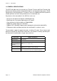
Section 1: Introduction 1.1 GENERAL SPECIFICATIONS The SATO LM 408e and 412e are dual-use (Thermal Transfer and Direct Thermal) high performance labeling solutions designed for logistics and manufacturing sectors. Based mechanically on the field-proven CL ‘enhance’ series, the LM408e and LM412e promise reliable operation and consistent performance at a reasonable cost.
Section 1: Introduction 1.
Section 1: Introduction Specification Model LM408e Model LM412e Media Characteristics Media Types supported Thermal transfer or direct thermal: 0.08 to 0.
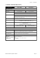
Section 1: Introduction 1.1 GENERAL SPECIFICATIONS (CONT’D) Specification/ Model Name LM408e and LM412e Interface Characteristics External connectivity (Slot 1) Interface board ¤ Parallel (IEEE1284) ¤ RS-232C • READY/BUSY • XON/XOFF • Status 2/3 • Driver specific protocol • Status 5 ¤ USB (Ver. 1.1) ¤ LAN (10BASE-T/ 100BASE-TX automatic changeover) ¤ Wireless LAN (IEEE802.11b) Configuration and Functions User settings (via LCD) Operation Panel 1. Settings indications 2. Print speed 3.
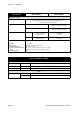
Section 1: Introduction 1.1 GENERAL SPECIFICATIONS (CONT’D) Specification/ Model Name LM408e and LM412e Barcoding Functions Barcodes Supported Stored Font Types Onedimensional code • • • • • • • • • • • • UPC-A/E, EAN8/13, JAN8/13 NW-7 INTERLEAVED 2 of 5 (ITF) INDUSTRIAL 2 of 5 MATRIX 2 of 5 CODE39, CODE93, CODE128 UCC/EAN128 RSS-14 MSI POSTNET BOOKLAND Customer barcode Twodimensional code • • • • • QR code model 2, Micro QR (Ver 8.1) PDF417 (Ver. 2.4, including micro PDF) MAXI code (Ver. 3.
Section 1: Introduction Specification/ Model Name LM408e and LM412e Physical Characteristics Dimensions W 430 mm x D 271 mm x H 321 mm (Standard) Weight 13 Kg (for a standard configuration) Power Supply Input voltage: AC100V - 120V or AC200V to 240V ±10% Power Consumption 180 W (peak) Standards Compliance CE(NEMCO-GS), UL/c-UL(MET), FCC (Class B), EN55022 (Class B), En61000, CCC, MIC Energy Saving: International Energy Star Program Environmental Conservation: Manufactured according to environmen
Section 1: Introduction This page is intentionally left blank Page 1-8 LM Basic 408e/412e Operator’s Manual
Section 2: Installation INSTALLATION 2 This section assists you in unpacking and installing the printer from the shipping container. You will also be guided through a familiarization tour of the main parts and controls.
SECTION 2: INSTALLATION SAFETY PRECAUTIONS SAFETY PRECAUTIONS Please read the following information carefully before installing and using the printer THE CAUTION SYMBOL Whenever the triangular Caution logo appears in this manual, pay special attention to the warning(s) cited below it. Failure to abide by the warnings may result in injury or damage to property.
Section 2: Installation GENERAL PRECAUTIONS • Head cleaning liquid (if supplied) is flammable. Never heat it or throw it into a fire. Keep it out of children’s reach to avoid accidental consumption. Should this occur, consult a doctor immediately. • When opening/closing the cover, beware of getting your fingers caught. Also, hold the opening/closing cover well so that it will not slip and fall on your hand. • After printing, the print head remains hot.
SECTION 2: INSTALLATION 2.1 UNPACKING When unpacking the printer, take note of the following: 1 The box should stay right-side up. Lift the printer out of the box carefully. 4 If the printer was been stored in the cold, allow it to reach room temperature before turning it on. 2 Remove the plastic covering from the printer. 5 Set the printer on a solid, flat surface. Inspect the shipping container and printer for any sign of damage that may have occurred during shipping.
Section 2: Installation 2.1.1 INCLUDED ACCESSORIES After unpacking the printer, verify that the following materials are in the accessories or packaging: Global Warranty document Additional information leaflets Power cable* Operator’s Manual Accessory CD-ROM* Two-pole adaptor* * Items marked with an asterisk may be different from what you see here, or may be excluded.
SECTION 2: INSTALLATION 2.1.
Section 2: Installation 2.1.2 PARTS IDENTIFICATION (CONT’D) IDENTIFYING THE MAIN PRINTER PARTS View of Front Panel 8888888888888888 8888888888888888 LINE STATUS PRINT FEED OFFSET PITCH DSW LCD screen Icons, prompts and system messages are displayed here. LINE button Takes the printer ONLINE (to proceed with printing) or OFFLINE (to perform configuration or other settings) Status LED FEED button . Feeds the label forward.
SECTION 2: INSTALLATION 2.2 LOADING THE CARBON RIBBON 1. Lift up the main cover. Make sure that the cover is pushed upwards until it rests firmly on top of the printer, in case it falls downwards and injures you. Main Cover Head Lock lever (purple) 2. Pull the purple Head Lock lever upwards in a counterclockwise direction. The print head assembly will be lifted up to allow ribbon loading. The rightmost white plastic shaft is the Ribbon Feeder Shaft. The left-most shaft is the Ribbon Take-Up Shaft. 3.
Section 2: Installation 2.3 LOADING LABELS This printer is designed to print on roll paper supplied via a separate label supply stand. The printing mechanism can be set to detect the I-mark on the paper to feed each label correctly. Note: For optimal print performance and durability, please use SATO-certified label and ribbon supplies on this printer. Using supplies not tested and approved for use by SATO can result in unnecessary wear and damage to vital parts of the printer, and may void the warranty.
SECTION 2: INSTALLATION 2.3 LOADING LABELS (CONT’D) 2.3.1 Loading Roll Paper 1. Lift up the main cover. Make sure that the cover is pushed upwards until it locks firmly in place so that it will not fall downwards and injure your hands. Release the purple Head Lock lever by pushing it upwards. The print head assembly will be lifted up to allow ribbon and label loading. 2. Load the ribbon rolls as described earlier. Pull down the Label Guide Plate. Then insert a label roll onto the Label Holder.
Section 2: Installation 2.3 LOADING LABELS (CONT’D) 2.3.2 Loading Fanfold Paper 1. Lift up the main cover. Make sure that the cover is pushed upwards until it locks firmly in place. Remove the fanfold slot cover by removing two screws. Pull the Head Lock Lever upward to release the print head assembly. 2. Stack the fanfold paper behind the printer and pull it through the fanfold slot and over the Label Holder.
SECTION 2: INSTALLATION 2.3 LOADING LABELS AND TAGS (CONT’D) 2.3.3 Adjusting the Paper Sensor Adjustment of the paper sensors (I-mark and Gap sensors) is usually not necessary, but the procedure is described here when you need to make adjustments. 1. Lift up the main cover. Make sure that the cover is pushed upwards until it locks firmly in place so that it will not fall downwards and injure your hands. 2. The sensor assembly is located just under the Label Guide Shaft.
Section 2: Installation 2.4 REPLACING THE PRINT HEAD Before attempting to replace the print head, it is advisable to contact your local dealer or service center so that they can assist you in case of problems. 1. Make sure the printer has been turned off for at least 30 minutes so that the print head is not hot. Lift up the front cover. 2. Locate the center screw that secures the print head, as shown in the picture. Unscrew it so that the print head comes loose. 3.
SECTION 2: INSTALLATION This page is intentionally left blank Page 2-14 LM Basic 408e/412e Operator’s Manual
Section 3: Configuration and Operation CONFIGURATION AND OPERATION 3 Before using the printer, it is best to read this manual thoroughly first. Otherwise, you may disturb default settings around which the instructional procedures in this manual are based on. 3.
Section 3: Configuration and Operation 3.2 THE OPERATION PANEL 8888888888888888 8888888888888888 LINE STATUS PRINT FEED OFFSET PITCH DSW LCD screen Icons, prompts and system messages are displayed here. LINE button Takes the printer ONLINE (to proceed with printing) or OFFLINE (to perform configuration or other settings) Status LED FEED button Feeds the label forward. When it is pressed once, the equivalent of a sheet of paper or label is ejected.
Section 3: Configuration and Operation The chart below provides an overview of the way to access the different modes of the printer. 3.
Section 3: Configuration and Operation 3.3 ACCESSING THE VARIOUS PRINTER MODES (CONT’D) 3.3.
Section 3: Configuration and Operation The chart below provides an overview of the LCD menus and options presented to the user in the different modes. 3.3.
Section 3: Configuration and Operation The chart below provides an overview of the LCD menus and options presented to the user in the different modes. 3.3.
Section 3: Configuration and Operation The chart below provides an overview of the LCD menus and options presented to the user in the different modes. 3.3.
Section 3: Configuration and Operation 3.4 NORMAL MODES 3.4.1 Online Pressing the LINE button causes the printer to go ONLINE or OFFLINE alternately. When the printer is ONLINE, the following activities will be possible: • • • • ONLINE QTY:000000 The printer is ready to receive print data from the computer or other connected devices The printer is ready to start printing The QTY counter is reduced in value with every printed label Pressing the FEED button normally has no effect in ONLINE Mode.
Section 3: Configuration and Operation 3.4 NORMAL MODES (CONT’D) 3.4.4 Print Speed Pressing LINE repeated cycles through the various available speeds. The slowest speed is 2ips, while the highest speed is 6ips. The default speed for the LM Basic 408e is 4ips. PRINT SPEED 2 3 4 5 6 Press the FEED button to select a print speed. The screen for Pitch Offset appears. 3.4.4 Pitch Offset This screen lets you adjust the pitch offset by up to +/- 49mm. The default value is 0.
Section 3: Configuration and Operation 3.5 ADVANCED MODE 3.5.1 Advanced Holding down the LINE button when turning the printer ON causes the printer to go into the Advanced Mode. ADVANCED MODE In the following screens of Advanced Mode, you can control the Darkness Range, Zero Slash symbol, Auto Online option, Print Offset, Calendar settings, Ignore CR/LF function, Character Pitch and Head Check feature. Press the FEED button to begin. 3.5.
Section 3: Configuration and Operation 3.5 ADVANCED MODE (CONT’D) 3.5.6 Set Calendar If a Calendar chip has been installed, this screen allows you to set the time and date. The default is NO. Selecting YES calls up a screen for setting the Year, Month, Day, Hour and Minute respectively. SET CALENDAR YES NO CALENDAR 00/00/00 00:00 Press the LINE button to select YES or NO, and the FEED button to proceed. If YES is selected, press the FEED button to move the cursor over each value of the date and time.
Section 3: Configuration and Operation 3.6 SERVICE MODE 3.6.1 Service In this mode, pressing the LINE button brings you to the COUNTERS mode screen. Otherwise, press FEED to proceed to adjust service mode settings. SERVICE MODE In the following screens of Service Mode, you can control the Slice Level, Auto Line Feed, Feed On Error, Reprint W/Feed, Forward/Backfeed Amount, Forward/Backfeed Distance, Euro Code symbol, Menu Language, Command/LCD Priority.
Section 3: Configuration and Operation 3.6 SERVICE MODE (CONT’D) 3.6.6 Forward/Backfeed Amount This setting allows customization of the label feed/backfeed distance instead of the default setting. If DISTANCE is selected, the next menu appears, for setting of the amount of label feed/backfeed. Use the LINE button to select DISTANCE or DEFAULT, and if applicable, to set the amount of label feed/backfeed.
Section 3: Configuration and Operation 3.6 SERVICE MODE (CONT’D) 3.6.11 Ribbon Near End On/Off This screen lets you enable or disable the early detection and warning of the ribbon supply reaching an end. The default value is ENABLE RIBBON NEAR END ENABLE DISABLE Use the LINE button to select ENABLE or DISABLE, then press the FEED button for the next screen. 3.6.12 IEEE1284 ACK Signal If the printer is connected using an IEEE1284 cable, this setting appears.
Section 3: Configuration and Operation 3.7 COUNTERS MODE 3.7.1 Counters In this mode, pressing the LINE button brings you to the Motion Mode settings. Otherwise, press FEED to proceed to adjust the behavior of the built-in counters. COUNTERS MODE In the following screens of Counters Mode, you can choose between the Head Counter or Life Counter, see the Head Counter value, clear the Head Counter, and see the Life Counter value. 3.7.
Section 3: Configuration and Operation 3.8 MOVE MODE 3.8.1 Movements of Labels In this mode, pressing the LINE button returns you to the main Advance Mode screen. Otherwise, press FEED to proceed to adjust the behavior of the built-in counters. MOVE MODE In the following screens of Move Mode, you can control the following label motion options: Continuous or Tear Off, Pitch Sensor ON/OFF. 3.8.
Section 3: Configuration and Operation 3.9 TEST PRINT MODE 3.9.1 Select Test Print In this mode, you can choose from five types of test prints. The five settings in this mode are as follows: TEST PRINT MODE CONFIGURATION Use the LINE button to select the test print pattern to generate, the press the FEED button to confirm the setting and proceed to the next screen. 3.9.2 Test Print Size In this screen you can specify the print width for all the test print patterns except MEMORY.
Section 3: Configuration and Operation 3.10 DEFAULT SETTING MODE 3.10.1 Resetting the Printer In this mode, selecting YES will reset the settings in the printer to factory defaults. The default value for this screen is NO. DEFAULT SETTING YES NO Use the LINE button to select YES or NO. If YES is selected, the next screen appears. 3.10.2 Reset Completed The various settings listed below have been reset to factory defaults. Turn the printer OFF now.
Section 3: Configuration and Operation 3.11 PROTOCOL STORING 3.11.1 Protocol Download In this mode, DSW2-7=OFF for standard code, and DSW2-7=ON for non-standard code. Press the LINE to set the printer ready to receive protocol data. The following screen appears: USER DOWNLOAD PRESS LINE KEY USER DOWNLOAD WAITING 3.11.2 Loading Completed Proceed to send protocol data from the host PC. When the protocol code is received, the content being stored will be printed out.
Section 3: Configuration and Operation 3.12 MAINTENANCE MODE 3.12.1 Factory or All Clear Mode In this mode, the status of DSW2-4 determines whether you can access the Factory mode or the All Clear Mode. Set DSW2-4=ON first. Then the printer will remain Maintenance Mode until the DSW2-4 is set to OFF. COUNTERS MODE In the Factory Mode settings, you can change the following: Counter Clear, Print Size for test print width, and Start/Stop test print. In All Clear settings, you can clear the Counter/EEPROM.
Section 3: Configuration and Operation 3.12 MAINTENANCE MODE (CONT’D) 3.12.5 All Clear Mode ALL CLEAR MODE In All Clear settings, you can clear the Counter/EEPROM. Press the FEED button to proceed. 3.12.6 Counter/EEPROM clear In this screen you can choose to clear either the Head Counter or the EEPROM. The default value is COUNTER. Use the LINE button to select COUNTER or EEPROM as required. Press the FEED button to confirm the reset and proceed to the next screen. 3.12.
Section 3: Configuration and Operation 3.13 HEX DUMP MODE 3.13.1 LCD Status In the Hex Dump Mode, when data is received, a hex dump is printed. The LCD screen then shows the quantity of labels printed, and the printer status. 3.13.2 Hex Dump Mode in buffer In this mode, only the buffer data is dumped. The quantity of labels printed is updated on the LCD screen. ONLINE QTY: 000000 ONLINE QTY: 000000 The procedure for such a buffer dump is as follows: 1. Make sure the printer is turned OFF. 2.
Section 3: Configuration and Operation 3.14 DOWNLOAD MODE 3.14.1 LCD Status In the mode, the LCD shows whether the printer is ready to receive the Flash Download. At the screen shown here, proceed to send the program/font/command data from the host PC. The following screen then appears. The “>” sign is used to show the progress of the data transfer. FLASH DOWNLOAD READY XXXXXXX DOWNLOAD START>>>>>>>END 1. “>” means downloading has started. 2. “>>” means 1Mb of data has been received and processed. 3.
Section 3: Configuration and Operation 3.15 BOOT DOWNLOAD MODE 3.15.1 LCD Status In the mode, the LCD shows the Boot Downloader prompt. Press the FEED button to prepare the printer for the data. The following screen then appears. Start sending the data from the host PC. The next screen then appears: The “>” sign is used to show the progress of the data transfer. BOOT DOWNLOADER PRESS FEED KEY PROGRAM DOWNLOAD READY PROGRAM DOWNLOAD START>>>>>>>END 1. “>” means downloading has started. 2.
Section 4: Cleaning and Maintenance CLEANING AND MAINTENANCE 4 4.1 INTRODUCTION This section provides information on user maintenance for the LM Basic printer. The following information is covered here: • Cleaning the Print Head, Platen and Rollers • Adjusting print quality • Replacing the protective fuse • Replacing the protective Print Head 4.2 CLEANING THE PRINT HEAD, PLATEN AND ROLLERS The print head not only generates printouts of barcodes, but also graphics and text.
Section 4: Cleaning and Maintenance 4.3 HOW TO CLEAN THE PRINTER (WITH A CLEANING SET) If a carbon ribbon has been loaded into the printer, be sure to remove it before cleaning. Follow the instructions supplied with the cleaning set. Use the items to clean the following parts. Paper Sensor and Label Guide Print head and Rollers Head Lock Lever Roller Print Head Paper Sensor Platen Roller Feed Roller Label Guide 1. Lift up the main cover. 2. Unlatch the print head unit using the Head Lock Lever.
Section 4: Cleaning and Maintenance 4.4 HOW TO CLEAN THE PRINTER (CLEANING SHEET) The cleaning sheet is used for cleaning stubborn stains on the print head. 1. Lift up the front cover. 2. Unlatch the print head unit using the purple Head Lock lever. The print head is now accessible. 3. Remove the label and ribbon. 4. Put the head cleaning sheet between the print head and the platen roller. The coarse side of the cleaning sheet should face the surface of the print head elements. 5.
Section 4: Cleaning and Maintenance 4.5 ADJUSTING PRINT QUALITY Print quality can be optimized with regular cleaning and maintenance of the print head and components along the label path. Additionally, you can fine-tune print quality by adjusting print darkness and print speed settings via the front panel PRINT potentiometer and via the control panel LCD menu. 4.5.
Section 4: Cleaning and Maintenance 4.5 ADJUSTING PRINT QUALITY (CONT’D) 4.5.2 Adjusting Print Speed Besides varying the print darkness level to control print quality, you can also change the rate at which labels are printed. The Print Speed adjustment affects how much time is allowed for the print head elements to produce a printout. The more time given (i.e., lower print speed) the better the print quality.
Section 4: Cleaning and Maintenance This page is intentionally left blank Page 4-6 LM Basic 408e/412e Operator’s Manual
Section 5: Interface Specifications INTERFACE SPECIFICATIONS 5 5.1 INTERFACE TYPES The LM printer is supplied with a single interface of the user’s choice: typically a parallel interface is used for transmitting data to and from the host. However, note that no external signal interface is available as an option for connecting the printer to other peripherals.
Section 5: Interface Specifications 5.2 INTERFACE CARD DIP SWITCH SETTINGS (RS-232C) The LM Basic super-speed serial interface card (optional) contains DIP switches for controlling communication conditions. The DIP switch functions are: Switch No.
Section 5: Interface Specifications 5.3 INTERFACE CARD DIP SWITCH SETTINGS (LAN) The LM Series Local Area Network interface card (optional) contains DIP switches for initializing LAN configuration, LAN printing configuration, and LAN card self-diagnosis. The DIP switch functions are: Switch No.
Section 5: Interface Specifications 5.5 EXTERNAL SIGNAL INTERFACE Unlike the more advanced SATO printers such as the CL4XXe series, the LM printer cannot be fitted with an EXT Signal Interface card for sending printer information status to any device or LAN. If you need this functionality in future, please consider purchasing a SATO printer featuring the EXT signal interface as an option. 5.6 SERIAL INTERFACE SPECIFICATIONS (RS-232C) The serial interface of this printer conforms to the RS-232C standard.
Section 5: Interface Specifications 5.7 READY/BUSY Ready / Busy is the hardware flow control method for the serial interface on the printer.
Section 5: Interface Specifications 5.8 SINGLE JOB BUFFER Timing Chart — Normal Processing P ow er O N P ressing S tart / Stop K ey P ressing S tart / Stop K ey P rinter side Initial td ER td S T X · · E T X (1) RD S TX · · · · · · · · · · · · · · · · · · · · ET X (2) RS O ffline O nline P rinter status R eceive, analyze, edit (1) O nline R eceive, an alyze, edit (2) P rint (1) P rint (2) td: delay from when the printer recognizes the com pletion of an item until control of the E R .
Section 5: Interface Specifications 5.
Section 5: Interface Specifications 5.10 X-ON/X-OFF This transmission protocol informs the host if the printer can receive data or not, by sending the "XON" (Hex 11H) or "XOFF" (Hex 13H) code.
Section 5: Interface Specifications 5.
Section 5: Interface Specifications 5.
Section 5: Interface Specifications 5.13 IEEE 1284 INTERFACE The IEEE 1284 Interface on the printer complies with IEEE1284 standards. The ECP mode is recommended for LPT1 port settings. Make sure to change the LPT1 port settings through the BIOS settings. Basic Specifications Interface board Connector Signal level Communication settings Printer Amphenol (DDK) 57 to 40360 (Equivalent) Cable Amphenol (DDK) 57 to 30360 (Equivalent) Cable length Under 3 meters High level : + 2.4 to + 5.0 V Low level : - 0.
Section 5: Interface Specifications 5.13 IEEE 1284 INTERFACE (CONT’D) Pin Assignment Make sure to use a IEEE1284 compliant cable .
Section 5: Interface Specifications 5.13 IEEE 1284 INTERFACE (CONT’D) Pin Assignment With Centronics standards, each signal pin placement is as follows: However, the IEEE 1284-B type connector is compliant when connecting the IEEE1284 standard. Pin no.
Section 5: Interface Specifications 5.
Section 5: Interface Specifications 5.14 SINGLE JOB BUFFER (CONT’D) Timing Chart — Procedure during Paper End P ower O N P ap er E nd H ea d open H ead closed P ressing the Start / S top P rinter side DATA E S C A · · · · · · · · · · ES C Z (1) S T R O BE ACK BUSY S E LE C T PE F A U LT P rinter status O nline O fflin e R e ce iv e, an a lyz e, e dit (1) P rint (1) N o te : P aper E nd is cleared by closing the H ead .
Section 5: Interface Specifications 5.15 MULTI JOB BUFFER Timing Chart — Normal Process P ow er O N P aper E nd H ead op en H ead close d P re ssing the Start / S top P rin ter side DATA E S C A · · · · · · · · · · ES C Z (1) STROBE ACK BUS Y S E LE C T PE F A U LT P rinter status O n line O ffline R ece iv e , an a lyze, e dit (1 ) P rint (1) N ote: P a per E nd is cle ared b y closing the H e ad.
Section 5: Interface Specifications 5.
Section 5: Interface Specifications This page is intentionally left blank Page 5-18 LM Basic 408e/412e Operator’s Manual
Section 6: Troubleshooting TROUBLESHOOTING If you are unable to produce printouts on the LM Series printer, use this section to make sure the basics have been checked, before deciding you are unable to proceed any further. The section is divided into seven parts: • • • • • • 6 Observations Initial Checklist Checklist for the RS232C Serial Interface Understanding ON LINE, RIBBON, LABEL indicators Understanding the LCD error messages Understanding the LCD warning messages General Troubleshooting Guide 6.
Section 6: Troubleshooting 6.2 USING THE RS232C (SERIAL) INTERFACE 1. Is the RS232C Serial cable connected securely to your serial port on the PC and to the RS232C connector on the printer? (The standard SATO cable for RS-232 uses a 9 pin-female to a 25-pin male connector) Observations 2. Is the cable defective? At the very least, you should be using a “Null Modem Cable,” which crosses pins in a specific manner. This should enable your printer to print.
Section 6: Troubleshooting 6.3 UNDERSTANDING THE LCD ERROR MESSAGES When an error occurs, or when the printer needs to alert the user of something important, the message on the LCD screen will contain the necessary information. Additionally, the Status LED may light up or blink in combination with the LCD message. There is no built-in buzzer in the LM 408e/412e to provide audible warnings On error, turn the printer OFF and ON again to verify the error..
Section 6: Troubleshooting 6.4 TROUBLESHOOTING GUIDE Symptom: The display remains blank when the power switch is pressed. No. What to check Remedy 1 Has the power cable been inserted into the power outlet securely? Insert the power cable securely into the outlet. 2 Is the power cable damaged? Inspect the power cable for signs of damage. If possible, try using another printer power cable.
Section 6: Troubleshooting 6.4 TROUBLESHOOTING GUIDE (CONT’D) Symptom: Low quality print No. What to check Remedy 1 Are the paper and carbon ribbon set correctly? Check if the paper and carbon ribbon are securely fixed. Also, lower the headopen lever of the print head unit, and check if the paper and carbon ribbon are in the normal position. 2 Are the paper and carbon ribbon set correctly? Check the paper and carbon ribbon. Set the print density again.
Section 6: Troubleshooting 6.4 TROUBLESHOOTING GUIDE (CONT’D) Symptom: Print position is misaligned No. What to check Remedy 1 Are the paper and carbon ribbon set correctly? Fix the paper and carbon ribbon securely. Also, release the print head unit, then set the paper and carbon ribbon to the normal position again. Finally, latch the print head back in place. 2 Is the platen roller dirty? If the platen roller is dirty, wipe off the dirt with the supplied cleaning set.
Section 7: Optional Accessories OPTIONAL ACCESSORIES 7 7.1 INTRODUCTION This section contains details of the optional accessories available for the LM printer: • • Interface boards Calendar IC 7.2 AVAILABLE INTERFACE BOARDS Interface boards enable the printer to exchange data with computers, computer networks and related input/output devices. By installing a different interface board, you can adapt the LM printer to fit in a wide range of related equipment and usage scenarios.
Section 7: Optional Accessories 7.3 OPTIONAL ACCESSORIES: INTERFACE BOARDS 7.3.1 RS-232C board Interface board DSW1 Connector Signal level Printer DB-25S (equivalent) (male) Cable DB-25P (equivalent) (female) Cable length shorter than 5m High level + 5 ~+ 12V Low level - 5 ~- 12V 7.3.
Section 7: Optional Accessories 7.3 OPTIONAL ACCESSORIES 7.3.3 IEEE-1284 board Interface board Connector Signal level Printer Anphenol (DDK) 57~40360 (equivalent) Cable Anphenol (DDK) 57~30360 (equivalent) Cable length: shorter than 1.5m High level + 2.v ~+ 5V Low leve + 0.0 ~- 0.4V 7.3.4 USB board Interface board Connector Connector TYPE"B" Cable length shorter than 5m Transmission Speed Full Speed 12Mbps, USB 1.
Section 7: Optional Accessories 7.3 OPTIONAL ACCESSORIES 7.3.5 LAN board Interface board Connector Cable type for 10BASE-T, 100BASE-TX Cable length shorter than 100m 7.4 OPTIONAL ACCESSORIES: OTHERS 7.4.1 Calendar IC Main PCB of printer Interface board Calendar IC Connector NA Technical details Incorporates a real-time clock for providing time and date information for label printing and other timing-related functions.