CL408-412e PRINTER SUPPLEMENTAL OPERATOR MANUAL PN: 9001159A
SATO America, Inc. 10350A Nations Ford Road Charlotte, NC 28273 Main Phone: (704) 644.1650 Technical Support Hotline: (704) 644.1660 Technical Support Fax: (704) 644.1661 E-Mail: satosales@satoamerica.com techsupport@satoamerica.com www.satoamerica.com WARNING THE EQUIPMENT REFERENCED IN THIS DOCUMENT COMPLIES WITH THE REQUIREMENTS IN PART 15 OF FCC RULES FOR A CLASS B COMPUTING DEVICE. OPERATION OF THIS EQUIPMENT IN A RESIDENTIAL AREA MAY CAUSE UNACCEPTABLE INTERFERENCE TO RADIO AND TV RECEPTION.
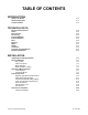
TABLE OF CONTENTS INTRODUCTION About This Manual General Description Control Features 1-2 1-3 1-4 TECHNICAL DATA Physical Characteristics Power Enviromental Processing Interface Modules Interface Modules Print Sensing Media Ribbon Command Character Font Capabilities Barcode Capabilities 2-2 2-2 2-2 2-2 2-2 2-2 2-2 2-3 2-3 2-3 2-3 2-4 2-5 INSTALLATION Unpacking & Parts Identification Printer Installation Site Location Cable Connection Media Selection Media & Ribbon Loading Operational Mode Selection Tear
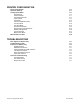
PRINTER CONFIGURATION Printer Configuration Dipswitch Settings Configuration Modes Normal Mode Advanced Mode User Download Mode Service Mode Card Mode Protocol Initialization Mode Counters Mode Test Print Mode Boot Download Mode Flash Memory Download Mode Default Settings Mode Hex Dump Mode Maintenance Mode Menu Definition Tables 4-2 4-3 4-6 4-6 4-7 4-8 4-9 4-10 4-11 4-12 4-13 4-14 4-15 4-16 4-17 4-18 4-19 TROUBLESHOOTING Error Signal Troubleshooting Troubleshooting Table Interface Troubleshooting Paralle
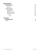
MAINTENANCE Cleaning Procedures Replacement Procedures Print Head Interface Board Fuse Adjustment Procedures Print Head Balance Print Head Alignment Ribbon Guide Label Sensor Positioning Ribbon Spindle Tensioning Operational Adjustments Pitch Offset Darkness 6-2 6-3 6-3 6-5 6-6 6-7 6-7 6-8 6-9 6-10 6-11 6-12 6-12 6-12 6-12 APPENDIX Print Setup Dimensions Label Reference Position Glossary CL408-412e Supplemental Manual 7-2 7-3 7-4 PN: 9001159A
INTRODUCTION • • • CL408-412e Supplemental Manual About This Manual General Description Control Features 1-1 PN: 9001159A
Unit 1: Introduction ABOUT THIS MANUAL This manual is laid out consistent with the product discussed and provides all of the information required for printer installation and operation by the purchaser. This manual also incorporates the use of special information boxes. Examples of these boxes and the type of information provided in each, are below. WARNING: PROVIDES INFORMATION THAT, IF UNHEEDED, MAY RESULT IN PERSONAL INJURY.
Unit 1: Introduction GENERAL DESCRIPTION The CL4e series printer brings the latest in technology to the world of thermal label printing by offering high-speed data transmission, unparalleled processing speed and large amounts of integrated memory to quickly and easily manage any label priinting requirement. These printers set new benchmarks in label throughput.The new generation RSIC processor provides high performance in label production even when printing directly from standard Windows.
Unit 1: Introduction CONTROL FEATURES This chapter identifies the interactive control features of the printer. These functions are defined generally here. More specific explanations will be found throughout this manual on how to use them. OPERATOR PANEL FEATURES LED STATUS DEFINITION • • • Illuminates green when online and terminates when offline. Blinks green when receiving data or the buffer is near full. Illuminates or blinks red when detecting a printer error.
Unit 1: Introduction LCD Display LINE STATUS Status Indicator LED FEED Function Keys PRINT DSW2 OFFSET PITCH Potentiometers DSW3 Dipswitch Complex Options Connector Cover-Open Sensor Label Taken LED Label Taken Potentiometer Figure 1-2, Operator Panel CL408-412e Supplemental Manual 1-5 PN: 9001159A
TECHNICAL DATA • • • • • • • • • • • • • CL408-412e Supplemental Manual Physical Characteristics Power Enviromental Processing Interface Modules Print Sensing Media Ribbon Command Regulatory Approvals Character Font Capabilities Barcode Capabilities 2-1 PN: 9001159A
Unit 2: Technical Data PHYSICAL CHARACTERISTICS Width 10.67 Inches (271 mm) Height 12.64 Inches (321 mm) Depth 16.92 Inches (430 mm) Weight 28.
Unit 2: Technical Data SENSING Gap Adjustable Reflective Eye-Mark Adjustable Ribbon Near End Enable/Disable Media Out Constant Ribbon Out Constant Cover Open Constant MEDIA Width Media Width: 0.866 to 5.04 Inches (22-128 mm) Media Width with Backing Paper: 0.984 to 5.16 Inches (25-131 mm) Length (Continous) Media Length: 0.237 to 7.01 Inches (6-178 mm) Media Length with Backing Paper: 0.354 to 7.13 Inches (9-181 mm) Length (Tear-Off) Media Length: 0.669 to 7.
Unit 2: Technical Data CHARACTER FONT CAPABILITIES MATRIX FONTS XU 5 dots W x 9 dots H (Helvetica) XS 17 dots W x 17 dots H (Univers Condensed Bold) XM 24 dots W x 24 dots H (Univers Condensed Bold) OA Font (OCR-A) LM408e: 15 dots W x 22 dots H LM412e: 22 dots W x 33 dots H OB Font (OCR-B) LM408e: 20 dots W x 24 dots H LM412e: 30 dots W x 36 dots H AUTO SMOOTHING FONTS XB 48 dots W x 48 dots H (Univers Condensed Bold) XL 48 dots W x 48 dots H (Sans Serif) VECTOR FONT Proportional or Fixed Spa
Unit 2: Technical Data BARCODE CAPABILTIES Linear Bar Codes UPC A/E JAN 8/13 EAN 8/13 Code 39 Code 93 Code 128 Interleaved 2 of 5 Industrial 2 of 5 Matrix 2 of 5 Bookland NW-7 MSI POSTNET UCC/EAN 128 NW-7 (Codabar) Two Dimemsional QR Code Data Matrix Maxi Code PDF417 Synthetic Symbol Ratios Bar Height 1:2, 1:3, 2:5, User definable bar widths 4 to 999 dots, User progammable Rotation Sequential Numbering Expansion Ratio of Character Graphics Form Overlay CL408-412e Supplemental Manual 0, 90, 180, an
INSTALLATION • • • • • CL408-412e Supplemental Manual Unpacking & Parts Identification Printer Installation Operational Mode Selection Interface Selection Accessories Installation 3-1 PN: 9001159A
Unit 3: Installation UNPACKING & PARTS IDENTIFICATION Unpack the printer as directed in the following procedure. 1 Place the shipping container (box) upright on a soid, flat surface. 2 Open the box, remove any loose items and the first layer of packing material. 3 Carefully lift the printer and accessories from the box and place them on a solid flat surface. 4 Remove the plastic covers from the packed items and visually inspect for physical damage.
Unit 3: Installation PRINTER INSTALLATION This chapter provides guidance on how to station, connect, and load the printer once unpacked. Following printer setup, procede to the next chapter for information on interface selection. SITE LOCATION • Stationed on a solid flat surface. • Stationed away from hazardous materials. • Stationed within operational distance of the host based on interface specifications. CABLE CONNECTION The procedure below provides instruction on typical cable connection.
Unit 3: Installation MEDIA SELECTION The size and type of the labels or tags to be printed should have been taken into consideration before printer purchase. Ideally, the media width will be equal to, or just narrower than, the print head. Using media that does not cover the print head will allow the platen roller to tread on it and wear it out. The media edge will also wear a groove in the platen roller affecting print quality.
Unit 3: Installation ME D MED MED IA MED IA MED IA MED IA MED IA IA IA Figure 3-3b, Fan-fold Media Loading Figure 3-3c, Ribbon Loading CL408-412e Supplemental Manual 3-5 PN: 9001159A
Unit 3: Installation OPERATIONAL MODE SELECTION There are two modes of printer operation; Dispense and Continuous. The difference between the two is the way that the label and paper backing is ejected. Before printer configuration, one must determine which mode will be used. This chapter identifies the funtional defferences between the two.
Unit 3: Installation CONTINUOUS MODE TRANSMISSION SENSOR REFLECTIVE SENSOR Base Print Position TEAR-OFF MODE TRANSMISSION SENSOR REFLECTIVE SENSOR Base Print & TearOff Position CUTTER MODE REFLECTIVE SENSOR Base Print Position Base Print Position Base Print & Cut Position DISPENSE MODE REFLECTIVE SENSOR TRANSMISSION SENSOR LABEL PRINT DIRECTION TRANSMISSION SENSOR Base Print Position Base Dispense Position Base Print & Dispense Position LINERLESS MODE REFLECTIVE SENSOR Base Print Position B
Unit 3: Installation INTERFACE SELECTION This unit presents the printer interface types and their specifications. These specifications include detailed information to assist in the selection of the most appropriate method for the printer to interface with the host. The five acceptable interface methods are: • • • • • RS232C High-Speed Serial IEEE1284 Parallel Universal Serial Bus (USB) Local Area network (LAN) Ethernet 802.
Unit 3: Installation DIPSWITCH SETTINGS SWITCH COMPONENT 1 Data Bit SETTINGS ON 7 Bits OFF 8 Bits 2 2&3 Parity 4 ON ON Reserved ON OFF ODD OFF ON EVEN OFF OFF NONE Stop Bit 5&6 Baud Rate 7&8 Protocol 3 ON 2 Bits OFF 1 Bit 5 6 ON ON 57600 bps ON OFF 38400 bps OFF ON 19200 bps OFF OFF 9600 bps 7 8 ON ON Reserved: Status2 & 3 (when compatible mode is OFF) ON OFF Protocol for Driver, Status5 OFF ON X-ON/X-OFF OFF OFF Ready/Busy READY/BUSY INTERFACE S
Unit 3: Installation READY/BUSY CABLE REQUIREMENTS DB9 DB25 HOST DIRECTION DB25 PRINTER 1 1 FG (Frame Ground) Bi-Directional 1 FG (Frame Ground) 2 3 RD (Receive Data) To Host 2 TD (Transmit Data) 3 2 TD (Transmit Data) To Printer 3 RD (Receive Data) 8 5 CTS (Clear To Send) To Printer DB9-6 4 RTS (Request To Send) 4 20 DTR (Data Terminal Ready) To Printer DB9-4 5 DSR (Data Set Ready) 6 6 DSR* (Data Set Ready) To Host 6 DTR (Data Terminal Ready) 5 7 SG (Signal Grou
Unit 3: Installation IEEE1284 PARALLEL INTERFACE The parallel interface is a plug-in module that can be installed by the user and conforms to IEEE1284 specifications. It automatically detects the IEEE1284 signals and operates in the high speed mode. If the IEEE1284 signals are not detected, it will operate in the slower standard Centronics mode. For this reason, an interface cable and host interface conforming to the IEEE1284 specification must be present to fully utilize the speed capabilities.
Unit 3: Installation UNIVERSAL SERIAL BUS (USB) The Universal Serial Bus (USB) interface is a Plug-In Interface Module that can be installed by the user. It requires a driver (shipped with each printer that has the interface installed) that must be loaded onto the PC and configured to support USB peripherals using Windows 2000 or above. Details for loading the USB driver are contained in the USB Interface Manual that is shipped with each printer with a USB Optional interface installed.
Unit 3: Installation SOFTWARE SPECIFICATIONS Corresponding Protocol TCP/IP Network Layer ARP, RARP, IP, ICMP Session Layer TCP, UDP Application Layer LPD, FTP, TELNET, BOOTP, DHCP NOTE: Print data can be sent by LPR and FTP of TCP/IP and dedicated socket protocol. Printer status is obtainable by dedicated socket protocol. NOTE: In the TCP/IP protocol enviroment, LPD and FTP are provided for printing; TELNET for variable setup; ARP, RARP, and BOOTP/DHCP for address setup.
Unit 3: Installation 802.11G WIRELESS The wireless print server provides easy printer interface with 802.11G Wi-Fi compliant networks free of wired connections. Each printer is shipped with an integrated driver and interface installed. The driver must be loaded onto the host computer and configured to run one of the supported protocols. SPECIFICATIONS Variable Data Rates 54, 11, 5.5, 2 and 1 Mbps Frequency Band 2.
Unit 3: Installation SOFTWARE SPECIFICATIONS Corresponding Protocol TCP/IP Network Layer ARP, RARP, IP, ICMP Session Layer TCP, UDP Application Layer LPD, FTP, TELNET, BOOTP, DHCP NOTE: Print data can be sent by LPR and FTP of TCP/IP and dedicated socket protocol. Printer status is obtainable by dedicated socket protocol. NOTE: In the TCP/IP protocol enviroment, LPD and FTP are provided for printing; TELNET for variable setup; ARP, RARP, and BOOTP/DHCP for address setup.
Unit 3: Installation READY/BUSY INTERFACE SIGNALS DB-9 PIN 14 PIN DIRECTION CENTRONICS 9 To Host 11 12 14 SIGNAL DEFINITION When Mode1 on the LCD is selected High Voltage = Online Print Job Waiting. When Mode2 on the LCD is selected High Voltage = Online. This goes low (0V) when the printer is offline. Reserved. To Host +24V +/- 10% @2A - Power for external devices. Frame Ground NOTE: The signals on pins 1, 3, 4, and 10 each have an open collector output. These pins normally measure +.
Unit 3: Installation Figure 3-8b, Timing Chart - Repeat Print Figure 3-8c, Timing Chart - Error Signals CL408-412e Supplemental Manual 3-17 PN: 9001159A
Unit 3: Installation ALL INTERFACES This chapter contains information that is applicable to all interface types offered. RECEIVE BUFFER The data stream is received from the host to the printer one job at a time. This allows the software program to maintain control of the job print queue so that it can move a high priority job in front of ones of lesser importance. A multiple job buffer allows the printer to continuously receive print jobs while compiling and printing other jobs at the same time.
Unit 3: Installation RECEIVE BUFFER CONTROL Causes For Receive Buffer Near Full Receive buffer near full occurs when the remaing free space of the buffer drops to 0.95MB of 2.95MB capacity or when the remaining free space is available for storing 50 of 500 items in the history buffer. Release Of Receive Buffer Near Full Receive buffer near full can be released when the remaining free space rises to 1.95MB or when the remaining free space is available for storing 200 items in the history buffer.
Unit 3: Installation ACCESSORIES INSTALLATION This chapter covers printer accessory installation procedures that are operator allowed. INTERFACE INSTALLATION The diagram below displays the physical installation of interface hardware. Refer to the Configuration unit of this manual for instructions on printer setup for the interface type chosen. 1. Switch off the printer and disconnect power supply cord. 2. Route interface cable (1, Figure 3-7) from host computer to interface board (2). 3.
PRINTER CONFIGURATION • • • • CL408-412e Supplemental Manual Printer Configuration Dipswitch Setting Configuration Modes Menu Definition Tables 4-1 PN: 9001159A
Unit 4: Printer Configuration PRINTER CONFIGURATION This unit provides in-depth instruction on printer configuration for operation and for some troubleshooting. The printer may be configured via the buttons and/or potentiometers loacated on the printer’s operator panel. All of the printer’s buttons, switches, and potentiometers are used either singularly, or in conjunction, to perform configuration activities.
Unit 4: Printer Configuration DIPSWITCH SETTINGS This chapter identifies the functions of the printer’s integrated dipswitches. The dipswitch complex is located on the printer’s operator panel and is an integral part of its configuration by enabling/disabling various operational features. Refer to the table below on switch designation and their specific functions. ATTENTION: Each dipswitch must be set for the printer to properly function.
Unit 4: Printer Configuration DSW1 FUNCTION DESCRIPTIONS FUNCTION DESCRIPTION Data Bit Sets the printer to receive either 7 or 8 bits of data for each byte transmitted. Parity Selects the type of parity used for error detection. Stop Bit Selects the number of stop bits to end each byte transmission. Baud Rate Select the data rate (bps) for the RS232 port. Protocol Selects the flow control and status reporting protocols.
Unit 4: Printer Configuration DSW3 DEFAULT SETTINGS 3-1 3-2 3-3 3-4 3-5 3-6 3-7 3-8 OFF OFF OFF OFF OFF OFF OFF OFF DSW3 CONFIGURATION 3-1 3-2 Operating Mode 3-1 3-2 OFF OFF Batch/Continuous OFF ON Tear Off ON OFF Cutter ON 3-3 Label Sensor 3-4 Backfeed 3-5 3-6 3-7 3-8 Print Start Signal External Signal Type Repeat Print via Ext Signal ON Dispenser OFF Sensor Used ON Sensor Not Used OFF Enabled ON Disabled OFF Disabled ON Enabled 3-6 3-7 OFF OFF Typ
Unit 4: Printer Configuration CONFIGURATION MODES This chapter provides an overview of the various configuration modes of the operation menu. All of the configuration activities are performed via the use of the operator panel located on the printer’s face. However, many settings may also be controlled via external software commands.
Unit 4: Printer Configuration ADVANCED MODE The Advanced Mode is provided to make basic printer operational adjustments. Typically, once these adjustments or settings have been made, they will not require additional address unless a new job is downloaded. Use the keys of the printer’s operator panel to select and enter the required options. Refer to the Menu Definition Tables in the following chapter to provide an explanation of each menu screen.
Unit 4: Printer Configuration USER DOWNLOAD MODE Allows the operator to download user specific data from a host system. Use the keys of the printer’s operator panel to select and enter the required options. Refer to the Menu Definition Tables in the following chapter to provide an explanation of each menu screen.
Unit 4: Printer Configuration SERVICE MODE Allows programming of various dimensional settings, sensor thresholds, and language options. Use the keys of the operator panel to select and enter the required options. Refer to the Menu Definition Tables in the following chapter to provide an explanation of each menu screen.
Unit 4: Printer Configuration CARD MODE This mode permits the configuration of an optional memory cartridge. This cartridge, when loaded, provides increased storage capacity for text and graphics. Use the keys of the printer’s operator panel to select and enter the required options. Refer to the Menu Definition Tables in the following chapter to provide an explanation of each menu screen.
Unit 4: Printer Configuration PROTOCOL INITIALIZATION MODE Allows non-standard protocol code to be returned to the default value. The default value is: STX (7BH), ETX (7DH), ESC (5EH), ENQ (40H), NULL (7EH), CAN (21H), Offline (5DH), EuroCode (D5H). Use the keys of the printer’s operator panel to select and enter the required options. Refer to the Menu Definition Tables in the following chapter to provide an explanation of each menu screen. DSW7: ON LINE + FEED + POWER ALT.
Unit 4: Printer Configuration COUNTERS MODE The printer has integrated counters to measure the accumilative activity of some features. The unit of measure is based on linear meters and includes a print head counter and a life counter. The head counter records the length of the media that has been printed since the print head was installed and should be reset each time the print head is replaced. The life counter meaures the lenght of media the printer as a whole has printed.
Unit 4: Printer Configuration TEST PRINT MODE Provides the specific sequence of events required by the operator, the printer, and the printer’s software for a test label to be printed. Test labels are designed to identify failures in configuration, adjustments problems, and mechanical defects. Use the keys of the printer’s operator panel to select and enter the required options. Refer to the Menu Definition Tables in the following chapter to provide an explanation of each menu screen.
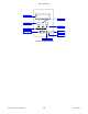
Unit 4: Printer Configuration BOOT DOWNLOAD MODE This download mode is used when the Firmware becomes corrupted and the normal download mode is not successful. Allows the program to be downloaded from the host computer. Figure 5-11 provides the specific sequence of events required by the operator, the printer, and the printer’s software. Use the printer’s operator panel to select and enter the required options.
Unit 4: Printer Configuration FLASH MEMORY DOWNLOAD MODE A Flash ROM internally stores/deletes font and custom designed character data. The data is sent from a host system to the printer. Use the printer’s operator panel to select and enter the required options. Refer to the Menu Definition Tables in the following chapter to provide an explanation of each menu screen.
Unit 4: Printer Configuration DEFAULT SETTING MODE The Default Settings Mode allows the operator to return the printer to the configuration state as received from the factory. Use the printer’s keys to select and enter the required options. Refer to the Menu Definition Tables in the following chapter to provide an explanation of each menu screen.
Unit 4: Printer Configuration HEX DUMP MODE The contents of the print buffer and the contents received before it may be examined through the use of the Hex Dump Mode. Each line of the printed data is enumerated in the first column, the second column contains the data in hexadecimal format, and the right column contains the same data in ASCII format. Use the printer’s operator panel to select and enter the required options.
Unit 4: Printer Configuration MAINTENANCE MODE The Maintenance Mode permits counter reset of various printer components. Use the printer’s operator panel to select and enter the required options. The printer has integrated counters to measure the accumilative activity of some features. The unit of measure is based on linear meters and includes a print head counter and a life counter.
Unit 4: Printer Configuration MENU DEFINITION TABLES NORMAL MODE (TABLE 4-1) MENU ONLINE QTY: XXXXXX OFFLINE QTY: XXXXXX DESCRIPTION Displays the printer’s operational status. The ONLINE status is displayed on the top line and the label quantity status is on the bottom. The message will be changed to OFFLINE whenever the printer is switched offline by pressing the LINE key. When a print job is received, the quantity line will indicate the number of labels to be printed.
Unit 4: Printer Configuration ADVANCED MODE (TABLE 4-2) MENU DESCRIPTION AUTO ONLINE YES NO The printer can be set to automatically go into the online mode when powered on. Otherwise, the printer starts in the offline state and must be manually placed online before it is ready to print. PRINT OFFSET V: +XXXX H: +XXX Print offset refers to the vertical and horizontal shifting of the entire print area relative to the label and the print start position.
Unit 4: Printer Configuration SERVICE MODE (TABLE 4-4) MENU DESCRIPTION ADVANCED MODE Is the first menu screen of the Advanced Mode. The Advanced Mode is provided to make basic printer operational adjustments. Typically, once these adjustments or settings have been made, they will not require additional address unless a new bob is downloaded. Is only a transitional menu screen to access the Service Mode. CARD MODE The Card Mode allows the operator to manage or format the expanded memory card.
Unit 4: Printer Configuration SERVICE MODE (TABLE 4-4) MENU DESCRIPTION SELECT LANGUAGE ENGLISH FRENCH GERMAN SPANISH ITALIAN PORTUGESE ENGLISH ENGLISH Allows the selection of the character set used by the printer. The world’s primary commercial languages are provided as options. PRIORITY SETTING COMMAND LCD Allows the selection of which type of operator programming will take priority precidence.
Unit 4: Printer Configuration CARD MODE (TABLE 4-5) MENU DESCRIPTION CARD ->MEMORY COPY SATOFONT Y/N Allows the copying of SATO fonts from the PCMCIA Memory card to the optional Flash ROM. CARD ->MEMORY COPY ALL Y/N Allows the copying of the entire contents from the PCMCIA Memory Card to the optional internal expanded memory. MEMORY ->CARD COPY ALL (OMB) Y/N Allows copying of the entire contents of the optional Expanded Memory to the PCMCIA Memory Card.
Unit 4: Printer Configuration PROTOCOL INITIALIZATION MODE (TABLE 4-6) MENU DESCRIPTION ALT. PROTOCOL DEFAULT COMPLETE Initialization is automatic when the proper keys and switches are activated. This is the only screen that will appear and will indicate that non-standard protocol code to be returned to the default value. The default value is: STX (7BH), ETX (7DH), ESC (5EH), ENQ (40H), NULL (7EH), CAN (21H), Offline (5DH), EuroCode (D5H).
Unit 4: Printer Configuration COUNTERS MODE (TABLE 4-7) MENU DESCRIPTION HEAD COUNTER CLEAR YES NO Allows the determination of whether or not to reset the print head counter to zero. DSP COUNTER CLEAR YES NO Allows the determination of whether or not to reset the dispenser counter to zero. CUT COUNTER CLEAR YES NO Allows the determination of whether or not to reset the cutter counter to zero. TEST PRINT MODE (TABLE 4-8) MENU DESCRIPTION Is the initial screen of the Test Print Mode.
Unit 4: Printer Configuration BOOT DOWNLOAD MODE (TABLE 4-9) MENU DESCRIPTION DOWNLOAD SELECT INTERFACE CARD Select the INTERFACE option for a standard download. PROGRAM DOWNLOAD READY Is an informational screen only and confirms that the printer is ready to receive the data. PROGRAM DOWNLOAD START > > > END Provides download status that the data is being received and its progression.
Unit 4: Printer Configuration HEX DUMP MODE (TABLE 4-12) MENU ONLINE QTY: XXXXXX DESCRIPTION Displays to indicate the printer is online and waiting to print HEX interpretation of data received by the print buffer. MAINTENANCE MODE (TABLE 4-13) MENU MAINTENANCE MODE DIPSW2-4 ON->OFF DESCRIPTION Is the first menu screen of the Maintenance Mode and provides a prompt on the action required to proceed to the Factory Mode.
Unit 4: Printer Configuration MAINTENANCE MODE (TABLE 4-13) MENU DESCRIPTION COUNTER CLEAR NONE ALL HEAD This screen allows the selection of which of the printer’s internal counters are to be cleared or not at all. Following the process, factory test printing is performed. PRINT SIZE SMALL Allows the selection of large (10cm) or small (4cm) font print size for the printing of a factory test page. These are the only two options.
TROUBLESHOOTING • • • • CL408-412e Supplemental Manual Error Signal Troubleshooting Troubleshooting Table Interface Troubleshooting Test Print Modes 5-1 PN: 9001159A
Unit 5: Troubleshooting ERROR SIGNAL TROUBLESHOOTING ERROR DISPLAYS ERROR LED 01 Machine Red MACHINE ERROR 02 Flash ROM Red EEPROM ERROR 03 Parity Red PARITY ERROR 1. Ensure correct communication parameters. 2. Check cables, cycle printer and resend. 3. Replace board. 04 Overrun Red OVERRUN ERROR 1. Check and correct communication cables and settings. 05 Framing Red FRAMING ERROR 1. Ensure host system and interface settings match. 2. Check and correct communication cables.
Unit 5: Troubleshooting TROUBLESHOOTING TABLE TROUBLESHOOTING TABLE IMAGE VOIDS Dirty print head. Clean print head. Damaged print head. Replace print head. Damaged electronics. Replace circuit board. Damaged or worn roller. Replace rollers. Poor label quality. Use higher quality media. Ribbon stock and media are mismatched. Consult with media supplier. RIBBON WRINKLING Poor head alignment. Adjust head balance and alignment. Excessive temperature setting Adjust temperature.
Unit 5: Troubleshooting NO PRINTED IMAGE Print head is disconnected. Ensure print head wiring harness is connected on each end. No voltage output. Replace fuse. Test power supply and replace as required. Defective print head. Replace print head and reset counter. Damaged electronics. Replace circuit board. Interface problems. Troubleshoot interface - refer to the next chapter. Data input error. Ensure correct data stream. PRINTER CREATES A BLANK LABEL. Data input error.
Unit 5: Troubleshooting INTERFACE TROUBLESHOOTING This chapter provides a checklist for the various interface types. Locate the checklist relative to the interface used and perform each of the troubleshooting tasks until the problem has been isolated. PARALLEL INTERFACE CHK TROUBLESHOOTING STEP Ensure the interface module is correctly installed. Run self-test to verify. Ensure the printer cable is connected to the appropriate LPT port on the host computer.
Unit 5: Troubleshooting LAN ETHERNET INTERFACE CHK TROUBLESHOOTING STEP Ensure the interface has been correctly configured. Wait two minutes and run self-test to verify. If a test label does not print, there may be a hardware problem. Ensure the cable and its ports are not defective. Ensure that a faulty print server or other protocol related scenarios are not creating a queue setup issue. Systematically perform checks and tests to isolate the cause.
Unit 5: Troubleshooting TEST PRINT TROUBLESHOOTING Chapter provides instruction on special printing to identify and resolve specific print problems. HEX DUMP Allows the operator to determine if there were problems in the downloading of data. TEST LABEL Allows the operator to identify specific problems regarding mechanical performance and setup. HEX DUMP MODE The contents of the print buffer can be examined using the Hex Dump Mode. In the left column, each line of data received is numbered.
Unit 5: Troubleshooting TEST LABEL PRINTING The test label is designed to assist in the identification of print problems. Follow the flow chart provided below to perform this activity.
Unit 5: Troubleshooting Compare this scale on each side to ensure the print is evenly spaced horizontally . Visually inspect these rows for voids indicating defective head elements. SAMPLE TEST LABEL Label Contents Will Vary Depending on Test Label Type . Displays the dip switch settings at the time of print. Line sharpness is determined by print speed and darkness. D S W 1 D S W 2 D S W 3 N O N E Clear line in print indicates the ribbon was wrinkled during printing.
MAINTENANCE • • • CL408-412e Supplemental Manual Cleaning Procedures Replacement Procedures Adjustment Procedures 6-1 PN: 9001159A
Unit 6: Maintenance CLEANING PROCEDURES Cleaning of the printer is a necessary maintenance activity to ensure print quality and longer printer life. There are tow basic types of cleaning involved; the removal of loose debris and the removal of residue. Use a soft cloth and/or a pneumatic blower to remove debris from the printer. This process should be performed prior to the removal of residue.
Unit 6: Maintenance REPLACEMENT PROCEDURES This chapter provides in-depth instruction on all primary component and assembly replacement, in addition to most secondary components. Use the text in conjunction with their accompanied graphics to ensure complete comprehension throughout the process. Especially observe all cautionary or warning notations. PRINT HEAD REPLACEMENT If the print head becomes damaged or worn, it can be easily removed and replaced without having to make critical adjustments.
Unit 6: Maintenance 3 1 4 Figure 6-1b, Print Head Replacement CL408-412e Supplemental Manual 6-4 PN: 9001159A
Unit 6: Maintenance INTERFACE BOARD REPLACEMENT Circuit boards generally have long lives due to the lack of moving parts. Generally, if a circuit board becomes defective, it is contributable to a negative external condition. If it is determined that the circuit board has become defective, search the printer over for possible visual factors that may have led to the damage. 1. Switch off the printer and disconnect power supply cord. 2.
Unit 6: Maintenance FUSE REPLACEMENT The fuse is wired to the power receptacle and protects the printer from power surges from the electrical source. If a surge of electricity reaches the fuse, its filiment will melt creating a disruption of the flow. In order to bridge the gap so the printer may again be functional, the damaged fuse must be replaced. 1. Switch off the printer and disconnect power supply cord. 2. Unscrew fuse cap (1, Figure 6-3) from fuse cylinder (2) located on rear housing cover (3).
Unit 6: Maintenance ADJUSTMENT PROCEDURES This chapter covers all of the printer and printer accessory adjustments. These adjustments include mechanical adjustments required following the replacement of components and assemblies, in addition to, the operational adjustments required following a job change. PRINT HEAD BALANCE ADJUSTMENT Print head balance is the equalization of pressure against the platen roller from one end to the opposite.
Unit 6: Maintenance PRINT HEAD ALIGNMENT Print head position has a direct impact on print quality. The print head must be parallel with the platen roller for the printed image to be consistent across the label. 1 Open the right housing cover to access print assembly (1, Figure 6-5a). 2 Ensure print head (2) is latched (3). 3 Look downward to print head (2) to locate head alignment plate (4, Figure 6-5b). 4 Ensure the values of alignment scales (A) and (B) are the same.
Unit 6: Maintenance RIBBON GUIDE ALIGNMENT If the print ribbon is not spread smoothly over the print head when it makes contact with the media, print voids will occur at the point of the ribbon fold. Typically, this is the result of the axis of one of the following not being perfectly parallel with the platen roller: ribbon spindle, print head, or ribbon guide. The purpose of the adjustable ribbon guide is to compensate for the axis deviations of the other two.
Unit 6: Maintenance LABEL SENSOR POSITIONING The label sensor assembly provides a mounting apparatus for the eye-mark, gap, and paper-end sensors. Position adjustment of the label sensor is not required when using standard label media. When non-standard media is used, place a section of the media on the media ramp oriented as if loaded for printing. Manually grasp the sensor assembly and move it laterally so that the sensor indicators embossed in its side are aligned with the reference marks on the media.
Unit 6: Maintenance RIBBON SPINDLE TENSIONING The printer has two ribbon spindles; one to supply ribbon medium from the rear of the printer past the print head to the spindle closest to the front for the purposes of rewinding the used medium. The rewind spindle is coupled to the drive train and draws the ribbon medium forward incrementally with the print media (label/tag) comparable with gearing ratios. For a proper function, the spindles must be individually adjusted with the correct drag.
Unit 6: Maintenance OPERATIONAL ADJUSTMENTS These operational adjustments are for fine tuning the printer as necessary following the configuration process and are largely confined to the four potentiometers located on the operator panel. Refer to the table below for their function. POTENTIOMETER PITCH DESCRIPTION/PROCEDURE Is to be used in conjunction with the configuration adjustments. Make course adjustments there and then fine tune here.
Unit 6: Maintenance CONTINUOUS MODE TRANSMISSION SENSOR REFLECTIVE SENSOR Base Print Position TEAR-OFF MODE TRANSMISSION SENSOR REFLECTIVE SENSOR Base Print & TearOff Position CUTTER MODE REFLECTIVE SENSOR Base Print Position Base Print Position Base Print & Cut Position DISPENSE MODE REFLECTIVE SENSOR TRANSMISSION SENSOR LABEL PRINT DIRECTION TRANSMISSION SENSOR Base Print Position Base Dispense Position Base Print & Dispense Position LINERLESS MODE REFLECTIVE SENSOR Base Print Position Ba
APPENDIX • • • CL408-412e Supplemental Manual Print Setup Dimensions Label Reference Position Diagram Glossary 7-1 PN: 9001159A
Unit 7: Appendix PRINT SETUP DIMENSIONS Gap 0.67 – 2.64" Eye-Mark 0.24 – 2.09" Eye-Mark, Gap, Paper-End Sensors Print Head LABEL PRINT DIRECTION 1.94" Print Width: 4.09"/4.20" Invalid Area for Print 0.93" 0.99" 1.
Unit 7: Appendix LABEL REFERENCE POSITION CONTINUOUS MODE TRANSMISSION SENSOR REFLECTIVE SENSOR Base Print Position TEAR-OFF MODE TRANSMISSION SENSOR REFLECTIVE SENSOR Base Print & TearOff Position CUTTER MODE REFLECTIVE SENSOR Base Print Position Base Print Position Base Print & Cut Position DISPENSE MODE REFLECTIVE SENSOR TRANSMISSION SENSOR LABEL PRINT DIRECTION TRANSMISSION SENSOR Base Print Position Base Dispense Position Base Print & Dispense Position LINERLESS MODE REFLECTIVE SENSOR B
Unit 7: Appendix GLOSSARY GLOSSARY AC (Alternating Current) Electrical current that reverses its direction regularly and continually. Accessory An optional assembly that may be used to provide an additional function. Active Tags RFID tags which use batteries as partial or complete source of power which are further differentiated by separating them into those with replaceable batteries and those which have the batteries inside a sealed unit. Also referred to as Utilized Active Tags.
Unit 7: Appendix GLOSSARY Bytes A collection of 8 bits used in the binary system. Capacity As it relates to RFID, the number of bits or bytes that can be programmed into a tag. This may represent the bits accessible to the user or the total number - including those reserved to the manufacturer (e.g., parity or control bits). Capture Window/Field Region of the scanner field in which an RFID tag will operate. Cavity A recessed area in something.
Unit 7: Appendix GLOSSARY Diode Allows current to flow in one direction but not the other to protect sensitive electronics. A diode functions by compositing two conductive materials with one possessing low resistance to electrical current on one side and high resistance on the other. Dipswitch Complex A group of tiny switches directly attached to a circuit board to enable configuration for a particular type of application. These switches are two-position: On/Off.
Unit 7: Appendix GLOSSARY Factory Programming Relative to RFID, the programming of information into a tag occurring as part of the manufacturing process resulting in a read-only tag. Field Programming In RFID, programming that usually occurs before the tag is installed on the object to be identified enabling the introduction of data relevant to the specifics of the application. However, the tag would typically have to be removed from its object.
Unit 7: Appendix GLOSSARY Key The button on a panel that may be pressed to send an electrical signal to influence a predetermined activity. Keyed A physical object shaped in a manner so as to prevent unwanted movement or to ensure desired movement. Kg (Kilogram) A unit of weight measure within the metric system. Kilo-Bytes Used to describe data transfer rates or storage capacity of approximately 1000 bytes.
Unit 7: Appendix GLOSSARY Modulation In RFID, the methods of altering carriers in order to transmit the encoded information. Nest A set of similarly shaped objects with one smaller and resting within the other. Nominal The point between a positive and negative deviation which is considered to be optimum. Nut A small metal block with a threaded hole through its center for screwing onto a bolt.
Unit 7: Appendix GLOSSARY Print Head The device on a direct thermal or thermal transfer printer containing the heating elements that causes an image to be transferred to print media. Processor A programmable device that performs all the instruction, logic, and mathematical processing in a computer - is the brains of the computer. The processor is a microchip that is installed on a motherboard (primary board) that coordinates hardware components. Also referred to as “CPU”.
Unit 7: Appendix GLOSSARY A system of finding the position or location of assets. RFID Tags A microchip attached to an antenna that is packaged in a way that it can be applied to an object. The tag picks up signals from, and sends signals to, a reader. The tag contains a unique serial number, but may have other information and come in many forms, such as smart labels that can have a barcode printed on it, or can simply be mounted inside a carton or embedded in plastic.
Unit 7: Appendix GLOSSARY Simultaneous To take place at the same time. Sleeve A thin hollow material that is inserted onto another to provide proportionate spacing. Snap Ring A circular clip that may be applied to a shaft, etc. to prevent another object from moving - used to retain objects in position. Solid An item that is not porous. An item that is not transparent or translucent. Spacer Any object of purpose to maintain a specific distance from two other objects - example: a sleeve or washer.
Unit 7: Appendix GLOSSARY Troubleshoot The act of locating the source of a problem or problems. Two-Dimensional Two of the projectories of an object: X axis is the distance left and right and the Y axis is the distance up and down. In a two-dimensional perspective, the Z axis is not recognized. Uniform The state of multiple objects being the same. Units Any fixed quantity, measure, etc.