
Printer User Manual


Page 9-2
Section 9. Optional Accessories
SATO CL408e/CL412e Service Manual
PN 9001078
Rev. B
9.2 Label Cutter Kit Installation - Guillotine Type
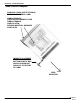
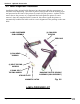
LABEL CUTTER KIT
MOUNTING BRACKET
(2) SELF TAPPING
SCREWS
LABEL CUTTER
ASSEMBLY
(2) PAN HEAD
SCREWS
STEP PROCEDURE
1. Switch the printer OFF but keep the power cable plugged in to discharge any
possible static charges.
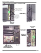
2. Remove the front door from the CL408/412e Printer. Fig. 9-2
3. Attach the mounting bracket using (2) self tapping screws. Verify that the
mounting bracket is correctly oriented. There are two small holes that
should fit on the small guide posts on the front door. The upright section of
the bracket should be facing towards the cutter assembly. Figs. 9-3 & 9-4
4. Slide the cutter assembly between the mounting brackets. Verify that the
two mounting slots on the left side of the cutter assembly are oriented
correctly over the guide screws. Fig. 9-5
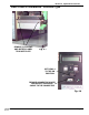
5. Attach the cutter assembly to the mounting bracket using (2) pan head
screws. Fig. 9-6
Route the interface cable from the cutter as shown in Fig. 9-5.
6. Remove (2) screws and detach the label tear off plate from the front of the
label exit area of the printer. Fig. 9-7
Reinstall the front cover onto the printer.
Fig. 9-1