
Printer User Manual


Page 9-20
Section 9. Optional Accessories
SATO CL408e/CL412e Service Manual
PN 9001078
Rev. B
PCMCIA Memory Expansion Installation
STEP PROCEDURE
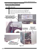
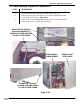
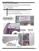
1. Remove (2) screws, nuts and standoffs from the Memory PCB Board for
mounting to the Main PCB Board. Fig. 9-35
2. Remove (2) screws and washers as shown in Fig. 9-35 for installing to
the Main PCB Board. Do not remove standoffs themselves.
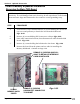
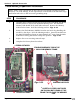
3. Refer to Fig. 9-36 for installation location on Main PCB Board.
Insert the (2) screws through the Main PCB Board and into the standoffs
as shown in Fig. 9-37
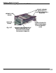
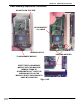
4. Place the Memory PCB Board down over the Main PCB Board so the the
connectors mate and the standoffs are aligned with the mounting holes
through the standoffs. Fig. 9-37
5. Secure one end of the Memory PCB Board with (2) screws previously
removed and the opposite end from the underside of the Main PCB Board
with (2) ea. screws and washers previously removed. Fig. 9-37
6. Reinstall the completed Main PCB assembly to the printer reversing the
Steps prior to the Memory Board installation.
7. Complete the Factory Reset Procedure.
NOTE: Many of the components on this board are susceptible to damage by static
electricity. To avoid damage from static electricity, do not unpack new circuit boards
from anti-static bags until instructed to do so and use a wrist grounding strap.
* Continue here after you have removed the Main PCB Board from
your printer.