CL608e/CL612e Printers Service Manual PN 9001079 Rev.
SATO America, Inc. 10350-A Nations Ford Rd. Charlotte, NC 28273 Main Phone: (704) 644-1650 Technical Support Hotline: (704) 644-1660 Fax: (704) 644-1661 http:\\www.satoamerica.com ã Copyright 2002 SATO America, Inc. The information supplied in this manual was current at time of publication. If you come across procedures that need clarification or find errors or have suggestions contact us at qc@satoamerica.
Table of Contents Section 1. Overview and Specifications 1 2 3 4 5 6 7 8 9 10 11 12 13 Page Overview ........................................................................................................... 1-1 Physical Characteristics .................................................................................. 1-2 Printer Features ................................................................................................ 1-3 Operation PanelDisplays ...........................................
Table of Contents Section 4. Electrical Checks and Adjustments 5b Pitch Offset Adjustment .................................................................................. 4-9 6 Label Gap Adjustment ................................................................................... 4-10 7 Eye-Mark Adjustment .................................................................................... 4-11 8 Feed/Backfeed Adjustment (Tear-Off) ..........................................................
Table of Contents Section 8. Troubleshooting 4 5 6 7 8 9 10 The RS232C Serial Interface ........................................................................... 8-4 The Universal Serial BUS (USB) .................................................................... 8-4 The LAN Ethernet Interface ............................................................................ 8-5 Error Signals ..................................................................................................
iv SATO CL608e/CL612e Service Manual PN 9001079 Rev.
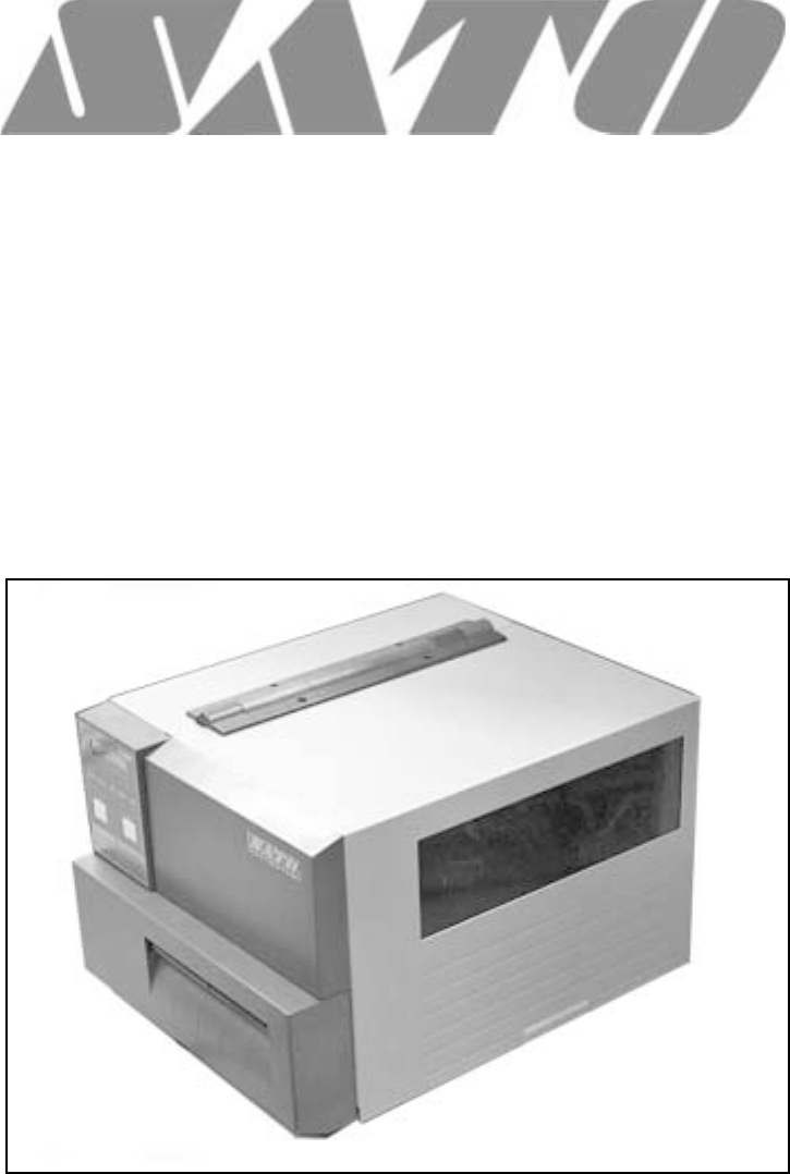
Section Overview and Specifications 1.1 Overview The SATO CL608e/CL612e Printers Service Manual provides information for installing and maintaining CL608e/CL612e Thermal Transfer printers. Step-bystep maintenance instructions are included in this manual with typical problems and solutions. It is recommended that you become familiar with each section in this manual before installing and maintaining the printer.
Section 1. Overview and Specifications 1.2 Physical Characteristics Depth Height FRONT ACCESS DOOR Width Dimensions C L 608e C L 612e Wide 13.8 in. (352 mm) D eep 16.9 in. (430 mm) High 11.7 in. (298 mm) Weight 41.9 lbs. (19 kg) Pow er Requirements Page 1-2 Voltage 115 -220 V (+/- 10%) 50/60 Hz (+/- 1%) Power Consumption 50W idle 130W Operating SATO CL608e/CL612e Service Manual PN 9001079 Rev.
Section 1. Overview and Specifications 1.3 Printer Features INTERFACE SLOT (SHOWN WITH CENTRONICS PARALLEL INTERFACE INSTALLED) EXTERNAL ACCESSORY CONNECTOR PCMCIA MEMORY EXPANSION SLOT POWER SWITCH AC POWER INPUT CONNECTOR AC FUSE COVER PLATE-REMOVE FOR ACCESS TO FAN-FOLD SLOTS Rear Panel PN 9001079 Rev. B INTERFACE SLOT Slot to plug in an interface adapter. An adapter must be connected before the printer is operational. The adapter types available are: RS232C Serial I/F Module, DP-25P.
Section 1. Overview and Specifications Printer Features RIBBON UNWIND SPINDLE LABEL SUPPLY GUIDE ACCESS DOOR RIBBON REWIND SPINDLE LABEL TEAR OFF PLATE MEDIA HOLDER SWITCHES AND SENSORS Refer to Section 1.6 Adjust the Media Knob based on the media you have loaded. For media up to 2.3 inches wide, use the "1" position. For media between 2.3 and 4.6 inches wide, use the "2" position. For media wider than 4.6 inches wide, use the "3" position.
Section 1. Overview and Specifications 1.4 Operation Panel/Displays LCD DISPLAY ADVISORY LED'S FEED KEY LINE KEY COVER ADVISORY LED'S POWER ONLINE LABEL RIBBON ERROR Illuminated when power is on. Illuminated when printer is ready to receive data. Turn ON/OFF by toggling the LINE key. Illuminated when label supply is out. Illuminated when ribbon motion sensor does not detect any ribbon motion. Illuminated when there is a system fault such as an open print head.
Section 1. Overview and Specifications Operation Panel/Displays POTENTIOMETERS VR1 (Print) To adjust print darkness (fine adjustment). VR2 (Offset) To adjust amount of back/forward feed for dispenser/cutter/tear-off bar position (+/- 3.75). VR3 (Pitch) To adjust home print position of the label (+/- 3.75 mm). VR4 (Display) To adjust the contrast of the LCD display. *DSW2 & DSW3 Dip Switches used to set operational parameters of printer. Refer to Section 2 for settings.
Section 1. Overview and Specifications 1.5 Components PRINT HEAD PLATEN RIBBON GUIDE PLATE LCD BOARD AND KB BOARD ON BACKSIDE OF PANEL TIMING BELTS STEPPER MOTOR PLATENS PN 9001079 Rev.
Section 1. Overview and Specifications Components POWER SUPPLY UNIT PLUG-IN INTERFACE CARD - CENTRONICS I/O SHOWN 1.6 Sensors and Switches RIBBON SENSOR: This sensor is a motion detector that signals the printer when the ribbon supply is turning. This sensor is used for both the ribbon end and ribbon near end sensing. HEAD LATCH LEVER: When the print head is opened, a micro switch is activated and the printer will stop printing. Error message will be displayed on the LCD operator panel.
Section 1. Overview and Specifications Switches and Sensors MEDIA HOLD DOWN: Open by lifting up on the release tab underneath the green tab marked "PUSH". The Media Hold Down is spring loaded and will remain in the up position. Close by pushing down on the same green tab.
Section 1. Overview and Specifications 1.7 Ribbon Use only SATO thermal transfer ribbons which were formulated expressly for use in all SATO printers. Use of other than approved ribbons may result in unsatisfactory print quality and/or damage to the print head and may void your warranty. 1.8 Installation Considerations Printer operation can be affected by the printer environment. The location of the printer should be free from dust, humidity and sudden vibrations.
Section 1. Overview and Specifications 1.10 Environment & Approvals Environmental CL608e/CL612e 410 to 1040 F (50 to 400 C) Operating Temperature Storage Temperature -00 to 1040 F (-200 to 400 C) Operating Humidity 15-85% RH, non-condensing Storage Humidity Max 90% RH, non-condensing Electrostatic Discharge 8K V Regulatory Approvals Safety UL, CSA RFI/EMI FCC Class A 1.
Section 1. Overview and Specifications General Printer Specifications Specification C L 608e C L 612e Sensing Transmissive See-thru Reflective Eye-Mark Continuous Form Movable Fixed Sensor not used Ribbon Maximum Width Length Thickness 6.75 in. (172 mm) 1345 ft. (410 m) 4.
Section 1. Overview and Specifications General Printer Specifications Specification C L 608e C L 612e Interface Modules Parallel IEEE 1284 Parallel RS232C (9600 to 57,600 bps) RS422/485 (9600 to 57,600 bps) Serial Hardware Flow Control (Ready/Busy) Software Flow Control (X-On/X-Off) Bi-directional Status 2,3 or 4 Serial Protocol Universal Serial Bus USB Version 1.
Section 1. Overview and Specifications 1.
Section 1. Overview and Specifications 1.
Section 1. Overview and Specifications Page 1-16 SATO CL608e/CL612e Service Manual PN 9001079 Rev.
Section 2 Configuration 2.1 Dip Switch Settings Two DIP switches (DSW2 & DSW3) are located inside the Front Access Door. These switches can be used to set: • Thermal transfer or direct thermal mode • Head Check Mode • Hex Dump Mode • Label sensor enable/disable • Single Job or Multi-Job Receive Buffer • Operation Mode DIP SWITCHES In addition, a third DIP switch (DSW1) is located on the optional RS232 Serial Adapter card and is used to set the RS232C transmit/receive parameters.
Section 2. Configuration Dip Switch Settings RS232 Transmit/Receive Setting (located on RS232 I/F Module) Data Bit Selection (DSW1-1): This switch sets the printer to receive either 7 or 8 data bits for each byte transmitted. DSW1 DSW1-1 SETTING ON Off 8 data bits On 7 data bits OFF 1 2 3 4 5 6 7 8 Parity Selection (DSW1-2, DSW1-3): These switches select the type of parity used for error detection.
Section 2. Configuration Dip Switch Settings Printer Set up Print Mode Selection (DSW2-1): Selects between direct thermal printing on thermally sensitive paper and thermal transfer printing using a ribbon. DSW2 DSW2-1 SETTING ON Off Transfer OFF On Direct Therm 1 2 3 4 5 6 7 8 7 8 Sensor Type Selection (DSW2-2): Selects between the use of a label gap or a reflective Eye-Mark.
Section 2. Configuration Dip Switch Settings Firmware Download (DSW2-6): Places the printer in the Firmware Download mode for downloading new firmware into flash ROM. DSW2 DSW2-6 SETTING Off Disabled On Enabled ON OFF 1 2 3 4 5 6 7 8 Protocol Code Selection (DSW2-7): Selects the command codes used for protocol control. DSW2 DSW2-7 SETTING ON Off Standard OFF On Non-Std. 1 2 3 5 4 6 7 8 M8400 Emulation Mode (DSW2-8): For emulating earlier series software commands.
Section 2. Configuration Dip Switch Settings Label Sensor Selection (DSW3-3): Enables or disables the Label Pitch sensor. If the sensor is enabled, it will detect the edge of the label and position it automatically. If it is disabled, the positioning must be under software control using Line Feed commands.
Section 2. Configuration Dip Switch Settings External Signal Type Selection (DSW3-6, DSW3-7): Both the polarity and signal type (level or pulse) of the external print synchronizing signal can be selected. See Section 3 for a definition of signal types. DSW3-6 DSW3-7 DSW3 SETTING Off Off Type 4 Off On Type 3 On Off Type 2 On On Type 1 ON OFF 1 2 3 5 4 6 7 8 Repeat Print via External Signal (DSW3-8): Allows an applicator or other device to reprint the last label of the print job.
Section 2. Configuration 2.2 Default Settings Dip Switch Selections All switches are placed in the Off position (default) except Receive Buffer for shipping.
Section 2. Configuration 2.3 LCD Panel Configuration The LCD Panel on the CL608e/CL612e is used in conjunction with the LINE and FEED switches by the operator to manually enter printer configuration settings. Many of the settings can also be controlled via software commands and in the case of conflict between software and control panel settings, the printer will always use the last valid setting.
Section 2. Configuration LCD Panel — Normal Mode When the printer is first powered on it displays the current ROM version of the printer then immediately displays the ONLINE mode. initializing rom v0.00.00.00 ONLINE QTY: 000000 The LCD Panel will display the ONLINE status on the top line of the display. The bottom line will contain the label quantity (QTY) status. The message will be changed to OFFLINE whenever the printer is switched offline by depressing the LINE key.
Section 2. Configuration LCD Panel — Normal Mode Print Speed Adjustment There are three Speed settings on the printer. The setting is listed on the bottom line of the display. The current setting is indicated by an underline under one of the speed settings. To change the setting: STEP 1. PROCEDURE Use the LINE key to step the underlined cursor to the desired speed setting. 4 = 4 in/s (100mm/s) 6 = 6 in/s (150mm/s) 8 = 8 in/s (200mm/s) 2.
Section 2. Configuration LCD Panel — Normal Mode Pitch Offset Adjustment STEP PROCEDURE 4. Press the FEED key to accept the setting and advance the cursor to the second digit. Again use the LINE key to step to the desired setting. Once it is correct, press the FEED key to advance to the next adjustment. Print a test label after completing the adjustments to ensure it is correct.
Section 2. Configuration LCD Panel — Normal Mode Cancel Print Job If the printer has a print job(s) loaded in memory, selecting YES will cause the job(s) to be cleared. The default selection is NO. Make sure that you want to cancel the print job before selecting YES as the job cannot be recovered and will have to be retransmitted to the printer. To cancel the print, perform the following steps: STEP cancel print job yes no PROCEDURE 1.
Section 2. Configuration LCD Panel— Advanced Mode Advanced mode is provided to make adjustments that require only occasional adjustments. Since they affect the basic operation of the printer, the procedure for entering this mode is designed to prevent someone from accidentally changing the settings. To Enter Advanced Mode: STEP PROCEDURE 1. Press the LINE key while simultaneously turning the power ON. When the printer emits one long beep, release the LINE key to display the first screen.
Section 2. Configuration LCD Panel — Advanced Mode Print Offset Print offset v:+0000 H:+000 Since the printer moves the label in discrete steps equal to the size of the print dot, the units of measure for Vertical and Horizontal Offset distance is dots. Vertical Offset is the distance down from the leading edge in dots (the edge of the label that comes out of the printer first) to the first vertical print position.
Section 2. Configuration LCD Panel — Advanced Mode Set Calendar (Continued) Calendar 00/00/00 00:00 STEP PN 9001079 Rev. B calendar 00/00/00 00:00 PROCEDURE 1. Year - The first display shown will have the two digit year selection underlined. You can scroll through the dates by pressing the LINE key. The year number will increase by one each time the LINE key is pressed until it reaches its maximum legal value (i.e., "99" for the year digits) at which point it will wrap around to the "00" setting. 2.
Section 2. Configuration LCD Panel — Advanced Mode Ignore CR/LF ignore cr/lf YES NO This setting tells the printer to strip out all carriage return/line feed pairs (CRLF) from the data stream, including graphics and 2D bar codes. It is used primarily to maintain compatibility with earlier models of SATO printers. STEP PROCEDURE 1. Use the LINE key to step the underlined cursor to either YES or NO. 2.
Section 2. Configuration LCD Panel —Card Mode The Card Mode allows the operator to manage the Expanded Memory (PCMCIA Card or Internal Expanded Flash ROM). The Card Mode is entered from the Advanced Mode display by pressing the LINE key once. Advanced Mode card Mode The Card Mode display indicates that the printer is in the Card Mode. To advance to the Mem Select (CC1), press the FEED key.
Section 2. Configuration LCD Panel — Card Mode Card ->MemoryCopy TrueTypeFont Y/N card ->MemoryCopy TrueTypeFont y/n This selection allows you to copy TrueType fonts from the PCMCIA Memory card installed in the Memory Card slot (on the rear of the printer) to the optional Flash ROM. STEP 1. PROCEDURE Use the LINE key to step the underlined cursor to the desired setting. IF Yes is selected, the printer will enter the Card Copy mode.
Section 2. Configuration LCD Panel — Card Mode Card ->MemoryCopy SatoFont Y/N card ->MemoryCopy SATOFont y/n This selection allows you to copy SATO fonts from the PCMCIA Memory card installed in the Memory Card slot (on the rear of the printer) to the optional Flash ROM. STEP 1. PROCEDURE Use the LINE key to step the underlined cursor to the desired setting. IF Yes is selected, the printer will enter the Card Copy mode. If No is selected, the display will advance to Card->MemoryCopy All mode.
Section 2. Configuration LCD Panel — Card Mode Card ->MemoryCopy All Y/N card ->MemoryCopy all y/n This selection allows you to copy the entire contents from PCMCIA Memory card installed in the Memory Card slot on the rear of the printer to the optional internal Expanded Memory. STEP 1. PROCEDURE Use the LINE key to step the underlined cursor to the desired setting. IF Yes is selected, the printer will enter the Card Copy mode. If No is selected, the display will advance to Card->MemoryCopy All mode.
Section 2. Configuration LCD Panel — Card Mode Memory->Card Copy All Y/N Memory ->cardCopy all y/n This selection allows you to copy the entire contents of the optional Expanded Memory to the PCMCIA Memory card installed in the Memory Card slot on the rear of the printer. STEP 1. PROCEDURE Use the LINE key to step the underlined cursor to the desired setting. IF Yes is selected, the printer will enter the Card Copy mode.
Section 2. Configuration LCD Panel — Card Mode card ->memoryCopy program y/n Card->Memory Copy Program Y/N This selection allows you to copy printer firmware from the PCMCIA Memory card to the printer. STEP 1. PROCEDURE Use the LINE key to step the underlined cursor to the desired setting. IF Yes is selected, the printer will enter the Card Copy mode. If No is selected, the display will advance to the mode display. 2. Confirm your selection by stepping the underline cursor to the Yes selection.
Section 2. Configuration LCD Panel — Card Mode Memory->cardCopy program y/n Memory->Card Copy Program Y/N This selection allows the user to copy the current firmware installed in the printer to a PCMCIA Memory Card. STEP 1. PROCEDURE Use the LINE key to step the underlined cursor to the desired setting. IF Yes is selected, the printer will enter the Card Copy mode. If No is selected, the display will advance to the mode display. 2.
Section 2. Configuration LCD Panel — Card Mode Card format yes no Card Format Yes No Before a PCMCIA card can be used, it must be formatted. Note: Formatting a card destroys all data currently stored on the Card. STEP 1. PROCEDURE Use the LINE key to step the underlined cursor to the desired setting. IF Yes is selected, the printer will enter the Card Format mode. If No is selected, the display will advance to the mode display.
Section 2. Configuration LCD Panel — Service Mode The Service Mode allows the operator to set up the basic operation parameters of the printer and is entered from the Advanced Mode. To Enter Advanced Mode: STEP 1. PROCEDURE Press the LINE key while simultaneously turning the power on. When the printer emits one long beep, release the LINE key to display the first screen. ADVANCED MODE 2. Press the LINE key twice to enter the Service Mode.
Section 2. Configuration LCD Panel — Service Mode Gap Input gap input [X.XV] [X.XV} [x.xv] [x.xv] GAP - When setting the "GAP" threshold, the voltage shown on the top line of the display must be measured with nothing but the backing in the sensor and then again with a label still attached to the backing. The formula to be used for setting the threshold is: (High Voltage Level + Low Voltage Level) x 0.5 = Start Value STEP PROCEDURE 1.
Section 2. Configuration LCD Panel — Service Mode Eye Input eye input [X.XV] [X.XV} [x.xv] [x.xv] EYE - When setting the "EYE" threshold, the voltage must be measured with nothing but the label under the sensor and then again with the printed "eye" mark under the sensor. The formula to be used for this is: (High Voltage Level + Low Voltage Level) x 0.5 = Start Value STEP PROCEDURE 1. Insert a label into the sensor and close the Label Hold-Down.
Section 2. Configuration LCD Panel — Service Mode Auto online feed yes no Auto Online Feed Yes No This selection specifies whether or not the printer will automatically feed a blank label when it is placed in the Online mode. STEP PROCEDURE 1. Use the LINE key to step the underlined cursor to the desired setting. IF Yes is selected, the printer will feed a blank label anytime it enters the Online mode. If No is selected, the display will advance to the mode display.
Section 2. Configuration LCD Panel — Service Mode forward/backfeed distance default Forward/Backfeed Distance Default This display will only appear when Backfeed is enabled (DSW3-4 = OFF). The maximum backfeed distance is 255mm. STEP PROCEDURE 1. Press the FEED key to use the default distance. This setting will be appropriate for use with standard labels with a 1/8" gap between labels and most tag stock applications. 2. Press the LINE key to set your own backfeed distance up to 255mm.
Section 2. Configuration LCD Panel — Service Mode euro code d5 Euro Code D5 This selection allows the user to specify the hexadecimal code for the character which is replaced with the Euro Character. The default is D5 Hex. STEP PROCEDURE 1. The underline cusor should be positioned underneath the first digit selection. Use the LINE key to step to the desired setting. 2. Press the FEED key to advance the underline cursor to the second digit of the desired hexadecimal code. 3.
Section 2. Configuration LCD Panel — Service Mode priority setting lcd command Priority Setting LCD Command This selection allows the user to assign a priority for Print Darkness, Print Speed and Print Offset. STEP PROCEDURE 1. Use the LINE key to step to the desired priority. If LCD is selected, the setting established via the LCD display/menu system will be used for an incoming label job, regardless of any different command settings.
Section 2. Configuration LCD Panel — Counters Mode The Counters Mode is provided to allow the user to access the internal printer counters and is entered from the Advanced Mode. To Enter Advanced Mode: STEP PROCEDURE 1. Press the LINE key while simultaneously turning the power on. When the printer emits one long beep, release the LINE key to display the first screen. ADVANCED MODE 2. Press the LINE key 3X to advance to the Counters Mode.
Section 2. Configuration LCD Panel — Counters Mode STEP 4. PROCEDURE Use the FEED key to select the desired setting. If you only want to read the counter value, select NO. If you want to read the counter and reset it to 0.0, place the underline cursor under YES. Once the desired setting is selected, press the FEED key to return to the Counter Mode display. counters mode To exit the Counters Mode power the printer off, then back on.
Section 2. Configuration LCD Panel — Test Print Mode Test Print Size 10 CM NOTE: This display does not appear when a Memory Test Print is chosen. Only a small Memory Test Print can be printed. test print Size 10 cm Once you have selected the type of test label to be printed, use the FEED key to accept the selection and the display advances to the Test Print Size display. This display allows you to select the label width. STEP PROCEDURE 1. Use the LINE key to select the label width.
Section 2. Configuration LCD Panel — Maintenance Mode — Factory Mode This function is used to clear counters and reset the printer's firmware. This procedure is used after upgrading the flash firmware or installing a new memory module. STEP PROCEDURE 1. Record all current dip switch positions, then place all switches in the OFFposition. 2. Place the DSW2-4 in the ON or up position. 3. Press the LINE and FEED key while simultaneously turning ON the power switch.
Section 2. Configuration LCD Panel — Maintenance Mode All Clear Mode This function is used to clear counters and reset the firmware and doesn't produce a test label. STEP PROCEDURE 1. Record all current dip switch positions, then place all switches in the OFF position. 2. Place the DSW2-4 in the ON or up position. 3. Press the LINE and FEED key while simultaneously turning ON the power switch. When the printer beeps, release the keys. The following screens will appear. initializing rom v00.00.00.
Section 2. Configuration LCD Panel — Clear Non-Standard Protocol The standard protocol codes used by the printer can be modified to accomodate the requirements of different host systems. However, if the printer is to be used with a system that does not use the custom protocol codes, they can be cleared and the default protocol codes reactivated. The default values are: STX = 7BH, ETX = 7DH, ESC = 5EH, ENQ = 40H, NULL = 7EH, CAN = 21H and OFFLINE = 5DH. Alt.
Section 2. Configuration LCD Panel — Download User Defined Protocol Codes User Download (Countinued) Press the Line Key STEP PROCEDURE 3. Transmit the download data command stream to the printer. 4. After the data has been received, the printer will beep and print a status label. If it does not beep and print a status label, the printer did not accept the data. 5.
Section 2. Configuration LCD Panel —Firmware Download Mode STEP PROCEDURE 1. Record all current dip switch positions, then place all switches in the OFF position. 2. Place the DSW2-6 in the ON or up position. 3. Turn ON the power switch. The following screens will appear. initializing rom v00.00.00.00 flash download ready Refer to the specific instructions provided with the flash firmware files provided by SATO America Technical Support or downloaded from the SATO America Web Site. www.
Section 2. Configuration 2.4 Sample Test Labels CONFIGURATION BAR CODE MEMORY HEAD CHECK FACTORY Page 2-40 SATO CL608e/CL612e Service Manual PN 9001079 Rev.
Section Interface Specifications 3.1 Overview ! This section presents the interface specifications for the CL608e/CL612e printers. CL608e/CL612e printers utilize a Plug-In Interface Module for maximum printer configuration flexibility. The following information is presented in this section.
Section 3. Interface Specifications Interface Types In order to provide flexibility in communicating with a variety of host computer systems, CL608e/612e printers use a Plug-In Interface Module. The IEEE1284 Interface module is shipped with the printer unless another interface type is specified at the time of the order. The other interfaces available are a high speed (to 57.6K bps) serial interface, an Ethernet interface or an optional Universal Serial Bus (USB) interface.
Section 3. Interface Specifications 3.3 The Receive Buffer The CL608e/CL612e printers have the ability to receive a data stream from the host in one of two ways. The receive buffer may be configured to accept one print job at a time or multiple print jobs. The single job print buffer is generally used by software programs that wish to maintain control of the job print queue so that it can move a high priority job in front of ones of lesser importance.
Section 3. Interface Specifications The Receive Buffer 0 1MB 2.95MB DTR High or X-On DTR Low or X-Off Buffer Available All printer error conditions (i.e., label out, ribbon out) will cause the printer to go busy (DTR "low" or X-Off) until the problem is corrected and the printer is placed online. The printer will also be busy if taken offline from the front panel. 3.
Section 3.
Section 3. Interface Specifications 3.5 RS232C Serial Interface The High Speed Serial Interface is a Plug-In Interface Module that can be installed in the printer by the user.
Section 3.
Section 3. Interface Specifications RS232C Interface Signals PIN DIRECTION 1 Reference 2 To Host 3 To Printer SIGNAL DESCRIPTION FG (Frame Ground) TD (Transmit Data) - Data from the printer to the host computer. Sends X-On/X-Off characters or status data (Bi-Directional protocol). RD (Receive Data) - Data to the printer from the host computer. To Host RTS (Request to Send) - Used with Ready/Busy flow control to indicate an error condition.
Section 3. Interface Specifications X-On/X-Off Flow Control X-On/X-Off flow control must be used whenever hardware (Ready/Busy) flow control is not available or desirable. Instead of a voltage going high/low at pin 20, control characters representing "Printer Ready" (X-On = 11 hexadecimal) or "Printer Busy" (XOff = 13 hexadecimal) are transmitted by the printer on pin 2 (Transmit Data) to the host. In order for this method of flow control to function correctly, the host must be capable of supporting it.
Section 3. Interface Specifications Universal Serial Bus (USB) Interface (Cont) General Specifications: Connector: Cable: USB Type B Plug 10ft (3 m) max. Host: Windows 98 USB Port Electrical Specifications: Power Supply: Power Consumption:: Bus Power through cable +5V@80ma 3.7 Ethernet Interface The Ethernet interface is a Plug-In Interface Module that can be installed by the user. It requires a driver (shipped with each printer) that has the interface installed.
Section 3. Interface Specifications 3.9 Accessory (EXT) Connector The EXT connector on the rear panel of the CL408e/CL412e printers is intended for use with external printer accessories such as label rewinders or applicators. The 14 pin Centronics type connector provides a choice of four different output signals along with various error conditions. A DB-9 to 14 pin Centronics adapter cable is provided for legacy applications.
Section 3. Interface Specifications NOTE: The signals on pins 1, 3, 4, 6, 9 and 10 each have an open collector output. These pins normally measure +.07V maximum when a true condition exists. If a false condition occurs, the voltage will drop to 0V. To achieve a signal level of +5V, you must add a 330 ohm, ¼ W pull-up resistor between the open collector output pin and Vcc (pin 13) as illustrated. This will provide a signal level of +5V for a true condition and 0V when a false condition exists.
Section 3. Interface Specifications Repeat Print Start of Print Cycle Print Start Input +5V Print Repeat Input +5V Print End Type 1 End of Print Cycle 0V 0V +5V 0V 20 Milliseconds Print End Type 2 +5V Print End Type 3 +5V Print End Type 4 +5V 0V 0V 0V Paper or Ribbon End Error Signals Motion Stopped +5V Paper End 0V +5V Ribbon End 0V +5V Machine Error 0V Paper/Ribbon Replenished Head Open Head Closed Print Motion PN 9001079 Rev.
Section 3. Interface Specifications Page 3-14 SATO CL608e/CL612e Service Manual PN 9001079 Rev.
Section Electrical Checks and Adjustments " 4.1 Overview This chapter describes how to check CL608e/CL612e Printers voltage levels and adjust threshold sensor voltages. The power supply converts 125 VAC into regulated DC voltages. The printer uses: +5V and +24V. These DC voltages are not adjustable, however you can measure these DC voltages at test points located on the PCB. Section 4-2 contains procedures for measuring DC voltage levels. You can adjust threshold voltage levels for label sensors.
Section 4. Electric Checks and Adjustments 4.2 Steps Prior to Some Procedures Some adjustments in this section require access to potentiometers and the test point connector located on the main PCB. Remove the LH cover for accessing the main PCB. STEP PROCEDURE 1. Switch the printer OFF and disconnect the AC power cord. 2. Remove (3) screws holding the left side cover to the printer. Raise the access door and loosen the (2) screws on the inside top of the printer.
Section 4. Electric Checks and Adjustments 4.3 DC Power Voltage Checks To check voltage levels, first check the fuses (Section 6.3) and replace if necessary. Then remove the LH cover, (Section 4.2) and perform the following steps. Addtional equipment required: STEP 1. TP Test Module Digital Multimeter PROCEDURE Refer to illustrations on pages 4-3 through 4-5. Attach the connector from the TP Test Module to the test port on the main PCB. Note correct positioning of connector.
Section 4.
Section 4. Electric Checks and Adjustments DC Power Voltage Checks LCD DISPLAY CABLE TO PCB PROBES DIAL COM VOLT GROUND SIG PIN PIN TP TEST MODULE Dial POS DIGITAL MULTIMETER DISC VOLTAGE RANGE TP TEST MODULE SG NC 0 +5V +4.8 to +5.2V CHA3 (+5V) - CHA1 (GND) 1 +2.0V +1.90 to +2.1V CHA4 (+2.0V) - CHA1 (GND) 2 +3.3V +3.1V to +3.5V CHA5 (+3.3V) - CHA1 (GND) 3 +24V +23.5V to +24.
Section 4. Electric Checks and Adjustments 4.4 Potentiometer Assignments & Adjustments VR to Adjust ITEM POSITION D IAL 5V 0 2V 1 3.
Section 4. Electric Checks and Adjustments Potentiometer Assignments & Adjustments POWER SUPPLY MAIN PCB VR5 IM VR4 GAP VR1 OFS INTERFACE BOARD VR2 DEM PN 9001079 Rev.
Section 4. Electric Checks and Adjustments 4.5a Print Position Adjustment Print Postition is adjusted with the VR3(PITCH) potentiometer on the Front Panel and/or VR1 potentiometer on the main PCB board. The following instructions are for adjusting the potentiometer on the Front Panel. Refer to Section 4.5b for making adjustments using the potentiometer on the PCB board. VR 3 Note: The VR3 (PITCH) is for changing the print position but not for the print stop position.
Section 4. Electric Checks and Adjustments 4.5b Print Position Adjustment Using VR1 potentiometer on the main PCB board. STEP VR1 adjustment range is +/- 3.75mm. PROCEDURE Refer to Section 4.2 for access to main PCB 1. Record all current dip switch positions, then place all switches in the OFF position and the power switch OFF. 2. Turn VR1 on the main PC Board to the center position. 3. Place DSW2-4 in the ON (up) position. 4.
Section 4. Electric Checks and Adjustments 4.6 Label Gap Adjustment Additional equipment required: STEP TP Test Module Digital Multimeter PROCEDURE Refer to Section 4.2 for access to main PCB 1. Turn VR4 (GAP) potentiometer on the main PCB all the way to the left. 2. Refer to Section 4.3. Set the digital multimeter to DC voltage measurement mode. Attach the connector from the TP Test Module to the test port on the main PCB. Note correct positioning of connector.
Section 4. Electric Checks and Adjustments 4.7 Eye-Mark Adjustment Additional equipment required: STEP TP Test Module Digital Multimeter PROCEDURE Refer to Section 4.2 for access to main PCB 1. Turn VR5 (IM) potentiometer on the main PCB all the way to the left. 2. Refer to Section 4.3. Set the digital multimeter to DC voltage measurement mode. Attach the connector from the TP Test Module to the test port on the main PCB. Note correct positioning of connector.
Section 4. Electric Checks and Adjustments 4.8 Offset Label Stop Position Adjustment Used for fine adjustment of label stop position for Tear Off, Cutter and Dispense Modes. The Label Stop Position is adjusted with the Offset potentiometer on the Front Panel. VR 2 Note: The stop position only is changed with the VR2 (OFFSET). The print position is changed with the VR3(PITCH). POTENTIOMETERS ARE LOCATED UNDERNEATH A FLIP - DOWN COVER OF THE FRONT PANEL STEP The VR2(OFFSET) adjustment range is +/- 3.75mm.
Section 4. Electric Checks and Adjustments 4.9 Ribbon Sensor Operation Verification No adjustment is provided for this sensor SEE PAGE 1-8 FOR SENSOR LOCATION PLACE DSW2-1 IN THE OFF POSITION STEP PROCEDURE 1. Flip down the cover on the front panel for access to the dip switches. 2. Record all dip switch positions, then place DSW2-1 in the OFF position and the power switch OFF. 3. Remove the ribbon from the printer and close the Head Open Lever. 4.
Section 4. Electric Checks and Adjustments 4.10 Ribbon Sensor Adjustment Additional equipment required: STEP TP Test Module Digital Multimeter PROCEDURE Refer to Section 4.2 for access to main PCB 1. Turn VR4 potentiometer on the main PCB all the way to the right. 2. Refer to Section 4.3. Set the digital multimeter to DC voltage measurement mode. Attach the connector from the TP Test Module to the test port on the main PCB. Note correct positioning of connector. Set the dial to 7. 3.
Section 4. Electric Checks and Adjustments 4.11 LCD Display Adjustment STEP PROCEDURE 1. Turn ON the power. 2. Confirm the backlight on the LCD is lit and message is displayed. 3. Adjust the display darkness with VR4 potentiometer (located underneath a flip-down cover of the front panel) as necessary. VR 4 POTENTIOMETERS ARE LOCATED UNDERNEATH A FLIP - DOWN COVER OF THE FRONT PANEL PN 9001079 Rev.
Section 4. Electric Checks and Adjustments 4.12 Print Darkness Adjustment STEP PROCEDURE 1. Turn VR1 potentiometer (located underneath a flip-down cover ot the front panel) to the center postion. 2. Turn ON the power. Press the LINE key to go off-line. Then press LINE and FEED keys simultaneously and the following message will display. print darkness 1(L) 2(M) 3(D) 3. Press LINE key and place the cursor under the print darkness desired, then press the FEED key to enter. 4. Turn OFF the power. 5.
Section Mechanical Adjustments # 5-1 Overview SATO CL608e/CL612e printers contain adjustable sub-assemblies. This means that during your regular maintenance, your service technicians are able to make adjustments to reset the printer to factory specifications thereby ensuring optimum performance of your printer.
Section 5. Mechanical Adjustments 5.2 Ribbon Clutch Adjustments Excessive ribbon unwind and rewind tension will result in variable ribbon motion and could be the cause of print quality problems. Follow the procedures 5.2.1 and 5.2.2 to verify that the ribbon unwind and rewind tensions are within specifications or if adjustment of either clutch is necessary. Required Equipment: 1 Kg Tension Gauge Ribbon Core, empty String 12mm Wrench #2 Pozidrv Screwdriver 5.2.
Section 5. Mechanical Adjustments Ribbon Clutch Adjustments RIBBON UNWIND SPINDLE ADJUST NUT LOCKING SCREW IS INSIDE ADJUST NUT Fig. 5-2 RIBBON REWIND SPINDLE TENSION GAUGE TENSION GAUGE STRING 950-1050g REWIND 450-550g UNWIND STRING EMPTY RIBBON CORES Fig. 5-4 Fig. 5-3 REWIND CLUTCH PN 9001079 Rev.
Section 5. Mechanical Adjustments Ribbon Clutch Adjustments 5.2.2 Ribbon Rewind Clutch Adjustment STEP 1. 2. 3. PROCEDURE Connect the power cable to the printer and AC outlet. Turn the printer ON. Raise the access door and remove the ribbon and label stock if installed. Fig. 5-1 Attach string to an empty ribbon core and place on the Ribbon Rewind Spindle. Wind the string tightly around the ribbon core in a single layer and in a clockwise direction. Attach the free end of the string to the tension gauge.
Section 5. Mechanical Adjustments 5.3 Print Head Position Adjustment Required Equipment: STEP PN 9001079 Rev. B Allen Wrench 2.5mm Ruler PROCEDURE 1. Refer to Section 7.2 and run a test print. Fig. 5-5 2. By adjusting the Allen head screws on the rear of the Stay, you can move the print head forward or backward. This allows you to position the burnline of the print head directly and evenly over the apex of the platen surface. Fig. 5-6 & 5-7 3.
Section 5. Mechanical Adjustments Print Head Position Adjustment MEASURE FROM BOTTOM OF BARCODE TO BOTTOM OF LABEL MEASURE FROM BOTTOM OF BARCODE TO BOTTOM OF LABEL TEST PRINT Fig. 5-5 ROTATION OF ALLEN MOVEMENT OF PRINT HEAD WRENCH CLOCKWISE COUNTER-CLOCKWISE TO THE FRONT BACKWARD STAY Fig. 5-6 STAY TURN SCREWS CW/CCW ALLEN WRENCH Page 5-6 Fig. 5-7 ADJUST SCREWS SATO CL608e/CL612e Service Manual PN 9001079 Rev.
Section 5. Mechanical Adjustments 5.4 Print Head Balance Adjustment Required Equipment: #2 Pozidrv Screwdriver 10mm wrench To optimize print quality, perform the following steps to adjust the Print Head Balance using head pattern as a guide. Proper adjustment is necessary to avoid ribbon wrinkle. STEP PROCEDURE 1. Connect the power cable to the printer and AC outlet. Turn the printer ON. 2. Raise the access door and load the ribbon and label stock.
Section 5. Mechanical Adjustments 5.5 Ribbon Roller Adjustment Required Equipment: #2 Pozidrv Screwdriver 10mm wrench NOTE: Only do this adjustment after adjusting ribbon wind and unwind tension in Section 5.2.1 and 5.2.2 STEP PROCEDURE 1. Connect the power cable to the printer and AC outlet. Turn the printer ON. 2. Raise the access door and load the ribbon and label stock. Fig. 5-1 3. Loosen the locking screws. Fig. 5-9 4. Turn eccentric with wrench. 5.
Section 5. Mechanical Adjustments 5.6 Feed Roller Adjustment (Label Tracking) Required Equipment: #2 Pozidrv Screwdriver 5.5mm wrench 1 Kg Tension Gauge Used for fine tuning. Adjusts pressure between upper and lower rollers. STEP PN 9001079 Rev. B PROCEDURE 1. Switch the printer OFF and disconnect the power cable. 2. Raise the access door and remove the label stock if installed. Fig. 5-1 3. Attach a strip of 20mm + wide liner backing paper to the end of the tension gauge.
Section 5. Mechanical Adjustments Feed Roller Adjustment (Label Tracking) BACKING PAPER RIGHT SIDE BACKING PAPER LEFT SIDE TENSION GAUGE Fig. 5-10 Fig. 5-11 MEDIA LID PULL PULL ADJUST SCREW & FIXING NUT ON BOTH ENDS OF MEDIA COVER Fig. 5-12 MOVE WITH FLAT BLADE SCREWDRIVER ADJUST PLATE LOCKING SCREW Page 5-10 Fig. 5-13 SATO CL608e/CL612e Service Manual PN 9001079 Rev.
Section 5. Mechanical Adjustments 5.7 Timing Belt Tension Adjustment STEP 1. 2. 3. PROCEDURE Remove (3) screws holding the left side cover to the printer. Raise the access door and loosen the (2) screws on the inside top of the printer. Lift off the left side cover. Fig. 5-14 Loosen the locking screws and belts will self-adjust. Tighten, but do not overtighten the screws. Fig. 5-15 Replace the left side cover.
Section 5. Mechanical Adjustments 5.8 Head Latch Adjustment The set-screws which attach the head latches to the latch shaft can become loosened during the operation of your printer. If you notice light printing on the left side of your labels, check the pairs of set-screws to be sure they are securely tightened. To correct this problem: Close the printhead and pull both latches so they are fully engaged to the latch posts. Tighten (2) set screws per latch.
Section 5. Mechanical Adjustments 5.9 Notch/Gap Sensor Adjustment The CL-608e/612e printers can position labels using either a label gap (transmissive) or a Eye-Mark (reflective) sensor. The sensor used is selected by DSW2-2. (page 2-3) The gap sensor position can be adjusted over a limited range. INSIDE EDGE OF PRINTER LOOSEN ADJUSTMENT SCREW AND REPOSITION IN SLOT. TIGHTEN SCREW EYE - MARK Minimum Size .12" (3 mm) W x .24" (6 mm) L MINIMUM INTER-LABEL GAP .
Section 5. Mechanical Adjustments Page 5-14 SATO CL608e/CL612e Service Manual PN 9001079 Rev.
Section Replacement Procedures 6.1 Overview $ SATO CL608e/CL612e Printers contain replaceable components and subassemblies. This section contains step-by-step instructions for removing and replacing the following components and sub-assemblies. PN 9001079 Rev.
Section 6. Replacement Procedures 6.2 Replacing the Main Circuit Board The Main Circuit Board contains the control electronics for the printers and is located behind L.H. cover of the printer. The I/O PCB interface and optional memory card unit if installed, which are attached to the main circuit board must first be removed. NOTE: Many of the components on this board are susceptible to damage by static electricity.
Section 6. Replacement Procedures Replacing the Main Circuit Board STEP PROCEDURE 3. Remove (2) screws holding the I/O PCB Interface from the back side of the unit. Pull away to detach the connector on the interface from the main circuit board. Figs. 6-2 4. Remove (2) screws to detach the main circuit board. Figs. 6-2 5. Note cable connection locations, then carefully disconnect the cables from the main circuit board. Figs. 6-3 6. Remove (3) screws holding the PC Board to the frame.
Section 6. Replacement Procedures Replacing the Main Circuit Board DISCONNECT CABLES REMOVE (2) SCREWS DISCONNECT CABLES Figs. 6-3 REMOVE SCREW Page 6-4 SATO CL608e/CL612e Service Manual PN 9001079 Rev.
Section 6. Replacement Procedures Replacing the Main Circuit Board * PRESS OUTWARD MEMORY MODULE PCB IN THE MAIN PCB MEMORY FRAME * PRESS OUTWARD Figs. 6-4 INDEXING NOTCHES * CAREFULLY PRESS OUTWARD ON TABS ON BOTH ENDS OF THE FRAME TO RELEASE THE MEMORY PCB. PN 9001079 Rev.
Section 6. Replacement Procedures Replacing the Main Circuit Board NO NOTCH ON THIS SIDE APPROXIMATELY 450 ANGLE INDEXING NOTCH INDEXING NOTCHES FLASH MEMORY MODULE INSERT THE FLASH MEMORY MODULE INTO THE MAIN PCB MEMORY FRAME AT APPROXIMATELY 450. NOTE THE INDEXING NOTCH ON THE MODULE. GENTLY PUSH DOWN TO SNAP INTO POSITION Figs. 6-5 Page 6-6 SATO CL608e/CL612e Service Manual PN 9001079 Rev.
Section 6. Replacement Procedures 6.3 Replacing the Fuses Fuse replacement is described in the following section. · 6.3.1 Removing and Replacing the Main Power Fuse · 6.3.2 Removing and Replacing the Internal Fuse NOTE: Before replacing a fuse, determine the cause of the overload condition. 6.3.1 Removing and Replacing the Main Power Fuse Required: STEP F3A, 250V Fuse Fuse PROCEDURE 1. Switch the printer OFF and disconnect the power cable. 2. Locate the fuse cap on the back of the printer.
Section 6. Replacement Procedures Replacing the Fuses Required: T3.15A, 250V Fuse or T1 Amp 250V Fuse To remove and replace these fuse(s) do the following: STEP PROCEDURE 1. Switch the printer OFF and disconnect the power cable. 2. Remove (3) screws holding the left side cover to the printer. Raise the access door and loosen the (2) screws on the inside top of the printer. Lift off the left side cover to expose the main PCB. Fig. 6-1 3. Refer to Fig. 6-7 and locate the appropriate fuse on the PCB.
Section 6. Replacement Procedures 6.4 Replacing the Power Supply The Power Supply is a non-repairable component with no servicable parts and is to be replaced as a complete assembly. STEP PN 9001079 Rev. B PROCEDURE 1. Switch the printer OFF and disconnect the power cable. 2. Remove (3) screws holding the left side cover to the printer. Raise the access door and loosen the (2) screws on the inside top of the printer. Lift off the left side cover to expose the main PCB. Fig. 6-1 3.
Section 6. Replacement Procedures Replacing the Power Supply REMOVE (2) SCREWS AND PULL AWAY TO DETACH IF INTERFACE CARD IS INSTALLED Figs. 6-8 REMOVE (2) SCREWS Fig. 6-9 Page 6-10 REMOVE (2) SCREWS TO DETACH MAIN CIRCUIT BOARD REMOVE (2) SCREWS SATO CL608e/CL612e Service Manual Fig. 6-10 PN 9001079 Rev.
Section 6. Replacement Procedures Replacing the Power Supply POWER SUPPLY REMOVE (2) SCREWS (POWER SUPPLY) Fig. 6-12 Fig. 6-11 REMOVE MOUNTING PLATE (WITH PCB ATTACHED) AND MOVE AWAY FROM THE POWER SUPPLY LIFT OUT POWER SUPPLY DETACH CABLE Fig. 6-13 LOWER THE MEDIA HOLDER Fig. 6-14 REMOVE BOTTOM AND TOP SCREWS Fig. 6-15 PN 9001079 Rev.
Section 6. Replacement Procedures 6.5 Replacing the Stepper Motor The Stepper Motor is used to transmit motion to the print mechanism for precise print positioning. The stepper motor transmits torque to the label feed roller, the platen roller, the ribbon feed roller, and the ribbon rewind spindle via a series of toothed timing belts and gears. STEP PROCEDURE 1. Switch the printer OFF and disconnect the power cable. 2. Remove (3) screws holding the left side cover to the printer.
Section 6. Replacement Procedures 6.6 Replacing the Timing Belts STEP PROCEDURE 1. Switch the printer OFF and disconnect the power cable. 2. Remove (3) screws holding the left side cover to the printer. Raise the access door and loosen the (2) screws on the inside top of the printer. Lift off the left side cover. Fig. 6-1 3. Remove the ribbon and label stock if installed. Fig. 6-19 4. Refer to Fig. 6-20 & 6-21 Locate Belts "A" and "B" in the electronics compartment. 5.
Section 6. Replacement Procedures Replacing the Timing Belts BELT "A" BELT "B" REWIND SPINDLE Fig. 6-20 BELT "A" GEAR TO ENGAGE FEED ROLLER IDLER FRONT PLATEN ROLLER BELT "B" REAR PLATEN ROLLER TENSION ADJUSTMENT IDLER MOTOR Fig. 6-21 Page 6-14 SATO CL608e/CL612e Service Manual PN 9001079 Rev.
Section 6. Replacement Procedures Replacing the Timing Belts BEARING DO NOT DISTURB THESE TWO SCREWS Figs. 6-22 REMOVE SCREW (ATTACHES TO REWIND SPINDLE) PULL REWIND SPINDLE FORWARD TO DISLODGE BELT "A" BEARING REMOVE & REPLACE BELT "A" DISLODGE BELT "B" FROM MOTOR SHAFT AND GEARS LOOSEN ADJUSTMENT IDLER SCREWS Figs. 6-23 PN 9001079 Rev.
Section 6. Replacement Procedures 6.7 Replacing the Print Head If the print head becomes damaged, it can be easily removed and replaced. No critical adjustments are required. Before you replace the print head, check the head counter values by printing a test pattern (Refer to Page 2-32). STEP PROCEDURE 1. Switch the printer OFF and disconnect the power cable. 2. Raise the access door and remove the ribbon and label stock if installed. Fig. 6-24 3.
Section 6. Replacement Procedures Replacing the Print Head REMOVE THE RIBBON AND LABEL STOCK REMOVE (2) STUD SCREWS HEAD LATCH LEVER Fig. 6-25 Fig. 6-24 PRINT HEAD DISLODGE AND REMOVE RIBBON GUIDE PLATE DISCONNECT CABLES PLATEN RIBBON GUIDE PLATE Fig. 6-26 PRINT HEAD PN 9001079 Rev. B Fig.
Section 6. Replacement Procedures Replacing the Print Head FOR THIS MODEL PRINTER SET SWITCH TO THE RIGHT Fig. 6-28 ALIGNMENT PINS RECONNECT CABLES Fig. 6-29 Page 6-18 SATO CL608e/CL612e Service Manual PRINT HEAD PN 9001079 Rev.
Section 6. Replacement Procedures 6.8 Replacing the Platen STEP PROCEDURE 1. Switch the printer OFF and disconnect the power cable. 2. Remove (3) screws holding the left side cover to the printer. Raise the access door and loosen the (2) screws on the inside top of the printer. Lift off the left side cover. Fig. 6-1 3. Remove the ribbon and label stock if installed. Fig. 6-30 4. Loosen but do not remove the screw holding clamp and platen to the frame. Fig. 6-31 5.
Section 6. Replacement Procedures Replacing the Platen REMOVE THE RIBBON AND LABEL STOCK PLATEN LOOSEN CLAMP AND SCREW HOLDING PLATEN TO FRAME SLIGHTLY LOOSEN ECCENTRIC SCREW Fig. 6-30 Fig. 6-31 REMOVE BELT LOOSEN IDLER SCREWS TO RELEASE BELT TENSION Page 6-20 Fig. 6-32 SATO CL608e/CL612e Service Manual PN 9001079 Rev.
Section 6. Replacement Procedures Replacing the Platen LOOSEN (2) SET SCREWS AND REMOVE PULLEY FROM END OF SHAFT ELECTRONIC COMPARTMENT SIDE MECHANICAL COMPARTMENT SIDE CL608 PLATEN CL612 PLATEN Fig. 6-33 Fig. 6-34 CL612 PLATEN REMOVE (2) SCREWS HOLDING RETAINER TO THE FRAME (SCREW IS PARTIALLY HIDDEN BY GEAR) Fig. 6-35 PN 9001079 Rev.
Section 6. Replacement Procedures Replacing the Platen DISPLACE PLATEN BY PULLING UP AND AWAY FROM HOLDING CLAMP Fig. 6-36 PULL PLATEN THROUGH HOLE IN FRAME AND OUT THE ELECTRONICS COMPARTMENT Fig. 6-37 HOLDING CLAMP WITH HEAD RELEASE LEVER IN PLACE BUSHING PLATE HOLDING CLAMP WITH HEAD RELEASE LEVER REMOVED FOR CLARITY AND SHOWING THE SPRING IN CORRECT POSITION SPRING END MUST NOT BE UNDER BUSHING PLATE Fig. 6-38 Page 6-22 Fig. 6-39 SATO CL608e/CL612e Service Manual PN 9001079 Rev.
Section 6. Replacement Procedures 6.9 Replacing the Ribbon Drive Clutch Washers Both the ribbon unwind and the rewind drive spindles incorporate a friction clutch assembly to control tension. The friction washers within these clutch assemblies are replaceable. The procedure is identical for both the off-wind and the on-wind clutch assemblies. DISASSEMBLE STEP PROCEDURE 1. Switch the printer OFF and disconnect the power cable. 2. Raise the main cover and remove the ribbon and label stock if installed.
Section 6. Replacement Procedures Replacing the Ribbon Drive Clutch Washers 6 5 4 3 2 Fig. 6-42 Fig. 6-41 USE 12mm OPEN END WRENCH AND PHILLIPS SCREW DRIVER TO REMOVE THE LOCKING SCREW AND ADJUSTMENT NUT 1 REMOVE & INSTALL PARTS IN THIS ORDER (SEE ITEM LIST 6A) 11 10 9a 9b 9b 7 9a 8 1 2 3 4 5 6 REWIND DRIVE SPINDLE Fig. 6-43 7 CONTINUED FROM FIG. 6-42 Page 6-24 Fig. 6-44 SATO CL608e/CL612e Service Manual UNWIND DRIVE SPINDLE PN 9001079 Rev.
Section 6. Replacement Procedures Replacing the Ribbon Drive Clutch Washers ASSEMBLE STEP PN 9001079 Rev. B PROCEDURE 1. For each spindle, position and fasten Item 11 Plate, with teeth facing outward with (2) screws. Except for Item 9, all items are the same for the ribbon unwind and ribbon rewind assemblies, List 6-A and Figs. 6-41 through 6-44. 2. Install Item 10 Felt Friction Washer onto the Ribbon Shaft and slide it against Item 11 Plate.
Section 6. Replacement Procedures Replacing the Ribbon Drive Clutch Washers ITEM 11 TEETH FACING OUTWARD TO ENGAGE ITEM 10 FELT WASHER Fig. 6-45 FASTEN ITEM 11 WITH (2) SCREWS LOCATION HOLES ITEM 9a/9b DISK PLATE Fig. 6-46 TEETH/SLOTS ON ITEM 9a DISC PLATE FACING TOWARDS FELT WASHER ITEM 8 RIBBON BOSS ALIGN HOLE WITH PEG Fig. 6-47 ITEM 8 RIBBON BOSS Page 6-26 INSERT PEGS INTO LOCATION HOLES Fig. 6-48 SATO CL608e/CL612e Service Manual ITEM 6 OIL-LESS WASHER PN 9001079 Rev.
Section 6. Replacement Procedures 6.10 Replacing the Ribbon Motion Sensor The Ribbon Motion Sensor is easily replaced for service. STEP PROCEDURE 1. Switch the printer OFF and disconnect the power cable. 2. Remove (3) screws holding the left side cover to the printer. Raise the access door and loosen the (2) screws on the inside top of the printer. Lift off the left side cover to expose the main PCB. Refer to Section 4-2. 3. Remove the ribbon and label stock if installed. Fig. 6-49 4.
Section 6. Replacement Procedures Replacing the Ribbon Motion Sensor ALIGNMENT PIN REMOVE SCREW Fig. 6-50 Fig. 6-51 Fig. 6-53 Fig. 6-52 PULL THE SENSOR CABLE AND CONNECTOR THROUGH THE FRAME HOLE UNPLUG SEN4 FROM THE PCB HARNESS Page 6-28 SATO CL608e/CL612e Service Manual PN 9001079 Rev.
Section 6. Replacement Procedures Replacing the Ribbon Motion Sensor REMOVE (2) SCREWS HOLDING SENSOR TO THE BRACKET Fig. 6-54 DISASSEMBLED RIBBON MOTION SENSOR AND MOUNTING BRACKET Fig. 6-55 PN 9001079 Rev.
Section 6. Replacement Procedures 6.11 Replacing the Paper End Switch (Micro-Switch) and the Bottom Half of the Notch/Gap and Eye-Mark Sensors MEDIA HOLD DOWN COVER (SHOWN IN RAISED POSITION) CONTAINS THE TOP HALF OF THE NOTCH/GAP SENSOR NOTCH/GAP SENSOR (TOP HALF) EYE-MARK SENSOR PAPER END SWITCH (MICRO-SWITCH) NOTCH/GAP SENSOR (BOTTOM HALF) Fig. 6-57 SENSOR LOCATIONS REMOVE THE RIBBON AND LABEL STOCK Fig. 6-56 Page 6-30 SATO CL608e/CL612e Service Manual PN 9001079 Rev.
Section 6. Replacement Procedures Replacing the Paper End Switch (Micro-Switch) and the Bottom Half of the Notch/Gap and Eye-Mark Sensors The Notch/Gap and Eye-Mark Sensors can be removed from the printer to clear label fragments and for service. No critical alignment is required when replacing these sensors. STEP PN 9001079 Rev. B PROCEDURE 1. Switch the printer OFF and disconnect the power cable. 2. Remove (3) screws holding the left side cover to the printer.
Section 6. Replacement Procedures Replacing the Paper End Switch (Micro-Switch) and the Bottom Half of the Notch/Gap and Eye-Mark Sensors RAMP PLATE REMOVE (3) SCREWS TO DETACH THE RAMP PLATE FROM THE RAMP FRAME Fig. 6-58 RAMP FRAME REMOVE (3) SCREWS TO DETACH THE RAMP PLATE FROM THE BACK PLATE Fig. 6-59 LOOSEN SCREWS FROM IDLER GEAR PLATE FOR ACCESS TO SCREW Fig. 6-60 Page 6-32 WIGGLE THE RAMP PLATE FREE FROM THE PRINTER SATO CL608e/CL612e Service Manual PN 9001079 Rev.
Section 6. Replacement Procedures Replacing the Paper End Switch (Micro-Switch) and the Bottom Half of the Notch/Gap and Eye-Mark Sensors BOTTOM HALF NOTCH/GAP AND EYE-MARK SENSORS PAPER END-SWITCH (MICRO-SWITCH) Fig. 6-61 NOTCH/GAP SENSOR (BOTTOM HALF) REMOVE (2) SCREWS Fig. 6-62 PAPER END SWITCH REMOVE (2) SCREWS Fig. 6-63 PN 9001079 Rev.
Section 6. Replacement Procedures 6.12 Replacing the Top Half of the Notch/Gap Sensor The media hold down cover contains the top half of the Notch/Gap Sensor and adjustment screws. It also contains the pressure roller. STEP PROCEDURE 1. Switch the printer OFF and disconnect the power cable. 2. Remove (3) screws holding the left side cover to the printer. Raise the access door and loosen the (2) screws on the inside top of the printer. Lift off the left side cover to expose the main PCB. Fig. 6-1 3.
Section 6. Replacement Procedures Replacing the Top Half of the Notch/Gap Sensor REMOVE SCREW TO DETACH MEDIA HOLD DOWN UNIT REMOVE MEDIA HOLD DOWN UNIT FROM THE FRAME Fig. 6-65 REMOVE (2) SCREWS TO OPEN COVER AND ACCESS THE NOTCH/GAP SENSOR Fig. 6-67 NOTCH/GAP SENSOR Fig. 6-68 PN 9001079 Rev. B Fig. 6-66 Fig.
Section 6. Replacement Procedures Replacing the Top Half of the Notch/Gap Sensor REMOVE SCREWS ALLEN HEAD SCREW Fig. 6-70 Fig. 6-71 ALLEN HEAD SCREW WITH COLLAR Fig. 6-72 Fig. 6-73 Fig. 6-74 DISLODGE BRACKET WITH SENSOR Page 6-36 REMOVE (2) SCREWS TO DETACH SENSOR FROM BRACKET SATO CL608e/CL612e Service Manual PN 9001079 Rev.
Section 6. Replacement Procedures 6.13 Replacing the Display Panel or Keyboard STEP PROCEDURE 1. Switch the printer OFF and disconnect the power cable. 2. Remove (3) screws holding the left side cover to the printer. Raise the access door and loosen the (2) screws on the inside top of the printer. Lift off the left side cover to expose the main PCB. Fig. 6-1 3. Raise the access door. Remove (1) screw from the cover that is attached to the frame.
Section 6. Replacement Procedures Replacing the Display Panel or Keyboard DISPLAY PANEL ASSEMBLY DISPENSER COVER COVER PLATEN REMOVE (1) SCREW Fig. 6-76 REMOVE (2) SCREWS BRACKET ATTACHED TO FRAME Fig. 6-77 REMOVE (2) SCREWS Fig. 6-79 Fig. 6-78 Page 6-38 ROTATE AND LIFT TO DETACH COVER SATO CL608e/CL612e Service Manual PN 9001079 Rev.
Section 6. Replacement Procedures Replacing the Display Panel or Keyboard DISPLAY PANEL ASSEMBLY REMOVE (1) SCREW DISPLAY PANEL ASSEMBLY Fig. 6-80 MECHANICAL SECTION SIDE REMOVE DISPLAY PANEL OR KEYPAD Fig. 6-81 REMOVE (2) SCREWS Fig. 6-82 PN 9001079 Rev.
Section 6. Replacement Procedures Page 6-40 SATO CL608e/CL612e Service Manual PN 9001079 Rev.
Section Factory Resets % 7.1 Overview The Factory Reset Mode allows you to: • • • • • PN 9001079 Rev.
Section 7. Factory Resets 7.2 Factory Settings/Test Print To reset the printer to the factory settings, perform the following steps. Caution: Resetting the printer will clear all registers. STEP PROCEDURE 1. Record all current dip switch positions, then place all switches in the OFF position. 2. Place the DSW2-4 in the ON or up postion. 3. Press the LINE and FEED key while simultaneously turning ON the power switch. When the printer beeps, release the keys. The following screens will appear.
Section 7. Factory Resets 7.3 Clear Head Counters To reset the printer to the factory settings, perform the following steps. Caution: Resetting the printer will clear all registers. STEP PROCEDURE 1. Record all current dip switch positions, then place all switches in the OFF position. 2. Place the DSW2-4 in the ON or up postion. 3. Press the LINE and FEED key while simultaneously turning ON the power switch. When the printer beeps, release the keys. The following screens will appear.
Section 7. Factory Resets 7.4 Clear Dispenser Counter To reset the printer to the factory settings, perform the following steps. Caution: Resetting the printer will clear all registers. STEP PROCEDURE 1. Record all current dip switch positions, then place all switches in the OFF position. 2. Place the DSW2-4 in the ON or up postion. 3. Press the LINE and FEED key while simultaneously turning ON the power switch. When the printer beeps, release the keys. The following screens will appear.
Section 7. Factory Resets 7.5 Clear Cutter Counter To reset the printer to the factory settings, perform the following steps. Caution: Resetting the printer will clear all registers. STEP PROCEDURE 1. Record all current dip switch positions, then place all switches in the OFF position. 2. Place the DSW2-4 in the ON or up postion. 3. Press the LINE and FEED key while simultaneously turning ON the power switch. When the printer beeps, release the keys. The following screens will appear.
Section 7. Factory Resets 7.6 Clear EEPROM To clear the EEPROM, perform the following steps. Caution: Resetting the printer will clear all registers. STEP PROCEDURE 1. Record all current dip switch positions, then place all switches in the OFF position. 2. Place the DSW2-4 in the ON or up postion. 3. Press the LINE and FEED key while simultaneously turning ON the power switch. When the printer beeps, release the keys. The following screens will appear. initializing rom v00.00.00.00 4.
Section 7. Factory Resets 7.7 Sample Test Prints LARGE TEST PRINT SMALL TEST PRINT ILLUSTRATIONS SHOWN ARE EXAMPLES ONLY AND MAY NOT EXACTLY MATCH YOUR OUTPUT PN 9001079 Rev.
Section 7. Factory Resets Page 7-8 SATO CL608e/CL612e Service Manual PN 9001079 Rev.
Section Troubleshooting 8 8.1 Overview This section has been devised to help you if you are unable to produce output on the CL608e/CL612e printers. Use this section to make sure the basics have been checked before deciding you are unable to proceed further. The design of the SATO CL608e/ CL612e printers is based upon proven technology and reliable components. When a problem occurs, the solution can be easily traced using the troubleshooting tables in this section.
Section 8. Troubleshooting 8.2 Initial Check List If you are unable to produce output on your printer, check the following before deciding you're unable to proceed any further. 1. Is the printer powered up and ON-LINE? 2. Is the ERROR light on the front panel OFF? If this light is ON, it may mean the Print Head Assembly or the Label Hold-Down is not closed and latched in position. 3.
Section 8. Troubleshooting The IEEE1284 Parallel Interface (Cont) c. Verify the following: You have not typed a "0" (zero) for an "o" (letter) or vice-versa. You have not missed any characters where they're needed. Make sure all printer command codes are capital letters. Your protocol codes are set for Standard or Non-Standard and data stream is consistent with these. 7.
Section 8. Troubleshooting 8.4 The RS232C (Serial) Interface 1. Is the RS232C Serial cable connected securely to your serial port on the PC (DB-25S Male) and to the RS232C connector on the printer? Warning: Never connect or disconnect interface cables (or use a switch box) with power applied to either the printer or the host. This may cause damage to the interface circuitry and is not covered by warranty. 2.
Section 8. Troubleshooting 8.6 Lan Ethernet Interface Installation Problems (Printer Does Not Come Up Ready) If you cannot print to the SATO enhanced ethernet adapter after you install it, check the following: 1. Make sure that the printer is powered on, all cables are securely plugged in, and that the printer is on-line. 2. Make sure there is a secure connection between the hub and the printer.
Section 8. Troubleshooting 4. If the job exits the queue but does not print, make sure that you have the correct driver installed. If you do, turn DSW2-4 on and cycle power. Try resending your print job. If something prints out at this point than we now that the connection is there but that the data is not correct. 5. Check the individual protocol troubleshooting sections in this chapter for additional causes of intermittent printer problems.
Section 8. Troubleshooting 5. Also verify that the host computer and the print server are either on the same subnet (for example, if the print server has a subnet mask of 255.255.255.0, the host must have the same subnet mask) or that the router is properly configured to pass data between the two devices. 6. If you are using a Berkeley-based UNIX, make sure that the daemon is started on Berkeley based systems with the command lpc start printer, where printer is the name of the local print queue. 7.
Section 8. Troubleshooting 1. If you cannot create a print queue, make sure that you have sufficient NetWare privileges. With NetWare 3.12 and earlier, you MUST be logged in as SUPERVISOR (not someone with Supervisor privileges). If you are having problems creating queues with NetWare 4.xx and later, try logging in as ADMIN. Also, make sure that you are not trying to run XAdmin32 with the Microsoft NetWare client (you must use the Novell 32-bit client). 2.
Section 8. Troubleshooting Windows NT/LAN Server Troubleshooting 2. Make sure that TCP/IP and lpr printing are installed and running on the Windows NT system or the LAN Server file server. 3. If you are having problems printing to the SATO enhanced ethernet adapter from a client PC that is connected to a Windows NTAS or LAN Server file server, verify that you can print a job directly from the DOS or OS/2 prompt on the file server.
Section 8. Troubleshooting 8.7 Error Signals The LCD display, Front Panel LED Indicators and Buzzer provide a visual/audio indication of the type of error encountered.
Section 8. Troubleshooting 8.
Section 8. Troubleshooting Print Quality Problems Symtom Probable Cause Suggested Corrective Action Light Images Low print head pressure Adjust head balance (Sec. 5.4) Ribbon not matched to label stock Use Premier II ribbon with a "1C" thermal transfer ribbon stock or equivalent for optimum results Low ribbon drive torque No ribbon movement Adjust ribbon drive clutch (Sec. 5.2) Foreign material on head Clean head and platen Poor head alignment Align print head (Sec. 5.
Section 8. Troubleshooting Print Quality Problems Symtom Probable Cause Suggested Corrective Action No Label Movement Loose/broken platen drive belt Adjust/replace belt Sec. 6.6) Incorrect label pitch sensor selected No +24 volt output No Printed Image Select correct label sensor type (DSW2-2) Replace fuse on main PCB (Sec. 6.3) Test power supply and replace if necessary (Sec. 6.
Section 8. Troubleshooting Print Quality Problems Symtom Probable Cause Suggested Corrective Action LA B E L LE D 0n Label sensor blocked Clean label sensor Incorrect label sensor threshold setting Adjust label sensor threshold (Sec. 4.6 & 4.7) Platen drive malfunction See Section 6.
Section 8. Troubleshooting 8.9 Head Pattern Examples FACTORY DEFAULT FEED DIRECTION POOR HEAD ALIGNMENT, BALANCE OUT OF ADJUSTMENT IRREGULAR UNEVEN TEXT GOOD ADJUSTMENT CLEAR, DARK, EVEN TEXT POOR HEAD ALIGNMENT, BALANCE OUT OF ADJUSTMENT ILLUSTRATIONS SHOWN ARE EXAMPLES ONLY AND WILL NOT EXACTLY MATCH YOUR OUTPUT PN 9001079 Rev.
Section 8. Troubleshooting Head Pattern Examples DIAGONAL VOIDS (WHITE STREAKS) THAT “WALK” ACROSS LABEL RIBBON WRINKLE POOR HEAD ALIGNMENT, POOR RIBBON TENSION, WORN PLATEN, FOREIGN MATERIAL, DAMAGED PRINT HEAD IMPROPER ALIGNMENT BOTTOM EDGE OF BAR CODE IS SHOWN NOT PARALLEL WITH EDGE OF LABEL FEED DIRECTION Page 8-16 SATO CL608e/CL612e Service Manual PN 9001079 Rev.
Section 8. Troubleshooting 8.10 Hex Dump Diagnostic Labels In addition to the User Test Print Labels, the printer contents of the receive and print buffers can be examined using the Hex Dump Test Labels. Print Buffer Hex Dump The contents of the Print Buffer can be examined using the Hex Dump mode. The label numbers each line of data received in the left hand column, the data in hexadecimal format in the center columns, followed by the same data in ASCII format in the right hand column.
Section 8. Troubleshooting Page 8-18 SATO CL608e/CL612e Service Manual PN 9001079 Rev.
Section Optional Accessories 9.1 Overview ' This section contains instructions for installing the following optional accessories: · Label Cutter Kit Installation PN 9001079 Rev.
Section 9. Optional Accessories 9.2 Label Cutter Kit Installation The Cutter is a field installable option. No critical adjustments or special tools are required. STEP 1. 2. 3. 4. 5. 6. 7. 8. 9. 10. 11. 12. Page 9-2 PROCEDURE Turn the printer OFF and disconnect the AC power cord. Remove (3) screws holding the left side cover to the printer. Raise the access door and loosen the (2) screws on the inside top of the printer. Lift off the left side cover. Figs.
Section 9. Optional Accessories Label Cutter Kit Installation RAISE THE ACCESS DOOR AND LOOSEN (2) SCREWS ON THE INSIDE TOP OF THE PRINTER REMOVE RIBBON AND LABEL STOCK Figs. 9-1 REMOVE (3) SCREWS FRONT COVER REMOVE SCREWS AT (5) PLACES TO DETACH FRONT COVER PN 9001079 Rev. B SATO CL608e/CL612e Service Manual Figs.
Section 9. Optional Accessories Label Cutter Kit Installation CUTTER UNIT REMOVE (2) SCREWS AND DISCARD BRACKET Fig. 9-3 Fig. 9-4 DETACH EXISTING CABLE FROM THE CUTTER PCB AT “CUTP” AND “CUTS”. INSTALL NEW CABLE AT SAME LOCATIONS ROUTE CABLE CONNECTORS FROM THE CUTTER THROUGH ACCESS HOLE IN PRINT ENGINE ASSEMBLY AND THROUGH THE HOLE IN THE ALUMINUM SIDE PLATE Figs. 9-5 Page 9-4 SATO CL608e/CL612e Service Manual PN 9001079 Rev.
Section 9. Optional Accessories Label Cutter Kit Installation DETACH SEN3 CONNECTOR FROM PCB BOARD AND REPLACE WITH CABLE CONNECTOR MARKED “CUTS” FROM CUTTER ATTACH CABLE CONNECTOR END MARKED “CUTP” FROM CUTTER TO CN2 ON POWER SUPPLY Figs. 9-6 CUTTER Figs. 9-7 SECURE CUTTER WITH SCREWS AT (5) PLACES PN 9001079 Rev.
Section 9. Optional Accessories 9-3 Label Dispenser Installation Installation of the optional Label dispenser into the printer adds the convenience of automatic label dispensing. Each label is printed, then peeled from the backing paper and presented at the front of the printer for removal by the operator. A photo electric sensor detects the presence of a completed label and signals the printer to await removal.
Section 9. Optional Accessories Label Dispenser Installation Components as Supplied in Kit REWINDER ASSEMBLY Fig. 9-8e PULLEY COVER Fig. 9-8f SCREWS SUPPLIED IN KIT Fig. 9-8g CABLE STAY Fig. 9-8h PN 9001079 Rev.
Section 9. Optional Accessories Label Dispenser Installation STEP PROCEDURE 1. Switch the printer OFF. 2. Remove (3) screws holding the left side cover to the printer. Raise the access door and loosen the (2) screws on the inside top of the printer. Lift off the left side cover. Figs. 9-9 3. Remove the ribbon and label stock if installed. RAISE THE ACCESS DOOR AND LOOSEN (2) SCREWS ON THE INSIDE TOP OF THE PRINTER REMOVE RIBBON AND LABEL STOCK Figs.
Section 9. Optional Accessories Label Dispenser Installation STEP PN 9001079 Rev. B PROCEDURE 4. Remove (3) motor mounting screws attaching motor to the frame. Fig. 9-10 5. Refer to Section 6.2 and remove the main circuit board. 6. Detach the front cover from the printer by removing (5) screws. Figs. 9-11 7. Refer to Fig. 9-8a & Figs. 9-12 Place spring on pin (both ends) and attach roller with flat area of shaft over spring and into hole (both ends). 8. Refer to Fig. 9-8b & Figs.
Section 9. Optional Accessories Label Dispenser Installation STEP PROCEDURE 15. Refer to Fig. 9-8a and Figs. 9-18 Install dispenser unit in its entirety to the front of the print cover previously removed in Step 6 with (5) screws. 16. Refer to Fig. 9-8h and Figs. 9-19 Install cable stay in the approximate position shown in Figs. 9-19. Route the dispenser cable under the stay and through opening in the printer to the main PCB connector harness @ SEN3. 17.
Section 9. Optional Accessories Label Dispenser Installation PLACE SPRING ON PIN (BOTH ENDS) AND ATTACH ROLLER WITH FLAT AREA OF SHAFT OVER SPRING AND INTO HOLE (BOTH ENDS) Figs. 9-12 INSTALL DISPENSER FEED ROLLER FROM THIS END IN SPACE VACATED BY MOTOR PN 9001079 Rev. B PLACE BEARING IN RIGHT SIDE FRAME. SLIDE ROLLER SHAFT INTO POSITION Figs.
Section 9. Optional Accessories Label Dispenser Installation Fig. 9-14d SECURE BRACKET TO WALL FROM OPPOSITE SIDE TENSION ROLLER ADJUSTMENT SLOT RIGHT SCREW Figs. 9-14 REWIND PULLEY Fig. 9-14c REMOVE "E" CLIP AND REMOVE PULLEY FROM BRACKET BEFORE INSTALLING ASSEMBLY Page 9-12 IDLER PULLEY IDLER GEAR Fig. 9-14b Fig. 9-14a ATTACH PULLEYS AND GEARS WITH HARDWARE AS SHOWN SATO CL608e/CL612e Service Manual PN 9001079 Rev.
Section 9. Optional Accessories Label Dispenser Installation Fig. 9-15 RUN THE "O" BELT FROM THE REWIND ASSEMBLY THROUGH THE BACK OF THE PRINTER AND ONTO THE REWIND PULLEY ATTACH THE REWINDER ASSEMBLY TO THE BACK OF THE PRINTER WITH (2) SCREWS REWIND PULLEY BACK OF THE PRINTER Fig. 9-16 ATTACH THE PULLEY COVER OVER THE EXPOSED PULLEY AND BELT WITH (1) SCREW Fig. 9-17 PN 9001079 Rev.
Section 9. Optional Accessories Label Dispenser Installation FRONT OF THE PRINTER DISPENSER UNIT IN OPEN POSITION Figs. 9-18 FRONT OF PRINTER LOOKING DOWN SECURE DISPENSER UNIT TO PRINTER WITH SCREWS AT (5) PLACES ROUTE CABLE FROM DISPENSER UNIT UNDER STAY AND THROUGH OPENING IN PRINTER TO THE MAIN PCB CONNECTOR HARNESS @ SEN3 Figs. 9-19 ATTACH CABLE STAY IN THIS APPROXIMATE POSITION. (Ref. Fig. 9-8h) Page 9-14 SATO CL608e/CL612e Service Manual PN 9001079 Rev.
Section 9. Optional Accessories 9.4 PCMCIA Memory Expansion Installation The Memory PCB Board provides the interface board for (1) PCMCIA memory card slot. Applicable Specifications Size Connector Pins Battery Write Protect Low Battery Detect PCMCIA Version 2.1 (JEIDA Version 4.1) Up to 4MB SRAM Up to 16MB Flash 68 Approximately two years (manufacturer dependent) Yes Yes STANDOFFS SHOWN AS RECEIVED.
Section 9. Optional Accessories PCMCIA Memory Expansion Installation STEP PROCEDURE 1. Switch the printer OFF. 2. Refer to Section 6.2 and remove the main circuit board. 3. Remove (2) screws, nuts and standoffs from the Memory PCB Board for mounting to the Main PCB Board. Fig. 9-20 4. Remove (2) screws and washers as shown in Fig. 9-20 for installing to the Main PCB Board. Do not remove standoffs themselves. 5. Refer to Fig. 21 for installation location on Main PCB Board.
Section 9. Optional Accessories PCMCIA Memory Expansion Installation REMOVE (2) SCREWS, NUTS AND STANDOFFS. THIS HARDWARE WILL BE MOUNTED ON THE MAIN PCB BOARD (STEP 3) Fig. 9-20 REMOVE (2) SCREWS AND WASHERS FROM THIS END OF STANDOFFS (STEP 4) CONNECTOR TO MAIN PCB BOARD CONNECTOR TO MEMORY BOARD HOLES FOR MOUNTING PN 9001079 Rev. B HOLES FOR MOUNTING Fig.
Section 9. Optional Accessories PCMCIA Memory Expansion Installation SECURE MEMORY BOARD WITH (2) SCREWS PREVIOUSLY REMOVED MEMORY PCB BOARD MAIN PCB BOARD Fig. 9-22 Page 9-18 SECURE FROM UNDERSIDE OF MAIN PCB BOARD WITH (2) SCREWS AND WASHERS PREVIOUSLY REMOVED. INSURE STANDOFFS ARE BETWEEN MAIN PCB AND MEMORY CARD SATO CL608e/CL612e Service Manual PN 9001079 Rev.
Section 9. Optional Accessories 9.5 Flash Memory Expansion Installation STEP PROCEDURE 1. Switch the printer OFF and disconnect the power cable. 2. Remove (3) screws holding the left side cover to the printer. Raise the access door and loosen the (2) screws on the inside top of the printer. Lift off the left side cover to expose the main PCB. Fig. 9-23 3. Carefully press outward on the tabs on both ends of the Main PCB Board Memory Frame to release the Standard Memory PCB.
Section 9. Optional Accessories Flash Memory Expansion Installation RAISE THE ACCESS DOOR AND LOOSEN (2) SCREWS ON THE INSIDE TOP OF THE PRINTER Fig. 9-23 REMOVE (3) SCREWS NO NOTCH ON THIS SIDE APPROXIMATELY 450 ANGLE INDEXING NOTCH INDEXING NOTCHES FLASH MEMORY MODULE Figs. 9-25 INSERT THE FLASH MEMORY MODULE INTO THE MAIN PCB MEMORY FRAME AT APPROXIMATELY 450. NOTE THE INDEXING NOTCH ON THE MODULE. GENTLY PUSH DOWN TO SNAP INTO POSITION Page 9-20 SATO CL608e/CL612e Service Manual PN 9001079 Rev.
Section 9. Optional Accessories 9.6 Real Time Clock Installation The Real Time Clock Chip allows the date and time to be maintained in the local printer rather than using the system clock. It consists of a special clock chip that replaces the EEPROM chip on the main PCB. STEP PROCEDURE 1. Switch the printer OFF and disconnect the power cable. 2. Remove (3) screws holding the left side cover to the printer. Raise the access door and loosen the (2) screws on the inside top of the printer.
Section 9. Optional Accessories Real Time Clock Chip Installation MAIN PCB BOARD REMOVE THE EEPROM CHIP INSTALL THE TIMEKEEPER CHIP IN VACATED LOCATION MARK ON CHIP IDENTIFIES PIN 1. BE SURE TO ALIGN CHIP CORRECTLY IN CHIP BLOCK SOCKET USING THE “U” SHAPED NOTCH AS REFERENCE PIN 1 PIN 1 Figs. 9-27 Page 9-22 SATO CL608e/CL612e Service Manual PN 9001079 Rev.
Section 9. Optional Accessories Factory Reset Procedure To reset the printer to the factory settings, perform the following steps. Caution: Resetting the printer will clear all registers. STEP PROCEDURE 1. Record all current dip switch positions, then place all switches in the OFF position. 2. Place the DSW2-4 in the ON or up postion. 3. Press the LINE and FEED key while simultaneously turning ON the power switch. When the printer beeps, release the keys. The following screens will appear.
Section 9. Optional Accessories Set Calendar After the Real Time Chip has been installed you must enter the Advance Mode to set the Calendar. Several steps are necessary in the Advanced Mode to get to the Calendar screen. For a full description of the steps in the Advanced mode leading to the Calendar screen refer to the Section 2 in the Service Manual. The following steps will take you to the Calendar screen where you can input the settings: To Enter Advanced Mode: STEP 1.
Section 9. Optional Accessories Set Calendar (Cont) STEP PN 9001079 Rev. B PROCEDURE 1. Year - The first display shown will have the two digit year selection underlined. You can scroll through the dates by pressing the LINE key. The year number will increase by one each time the LINE key is pressed until it reaches its maximum legal value (i.e., "99" for the year digits) at which point it will wrap around to the "00" setting. 2.
Section 9. Optional Accessories Page 9-26 SATO CL608e/CL612e Service Manual PN 9001079 Rev.
Section Spare Parts List 10.1 Overview The following parts lists are included for the CL608e/CL612e Printers: · Base Cover Assembly · Frame Assembly · Print Head Assembly · Ribbon Assembly · Feed Roller Assembly · Main PCB Assembly · Interface Option · Dispenser Assembly Option · Cutter Assembly Option · PCMCIA Memory Option Note: The spare parts information in this manual is accurate at the time of publication of this service manual and is subject to change without notice.
Section 10. Parts List 10.2 Base Cover Assembly Page 10-2 SATO CL608e/CL612e Service Manual PN 9001079 Rev.
Section 10. Parts List Base Cover Assembly PN 9001079 Rev.
Section 10. Parts List Base Cover Assembly Page 10-4 SATO CL608e/CL612e Service Manual PN 9001079 Rev.
Section 10. Parts List Base Cover Assembly PN 9001079 Rev.
Section 10. Parts List Base Cover Assembly Page 10-6 SATO CL608e/CL612e Service Manual PN 9001079 Rev.
Section 10. Parts List Base Cover Assembly NO. PN 9001079 Rev.
Section 10. Parts List Base Cover Assembly NO.
Section 10. Parts List Base Cover Assembly NO. PN 9001079 Rev.
Section 10. Parts List Base Cover Assembly Page 10-10 NO.
Section 10. Parts List CL612 CL608 10.3 Frame Assembly PN 9001079 Rev.
Section 10. Parts List Frame Assembly Page 10-12 SATO CL608e/CL612e Service Manual PN 9001079 Rev.
Section 10. Parts List Frame Assembly PN 9001079 Rev.
Section 10. Parts List Frame Assembly Page 10-14 SATO CL608e/CL612e Service Manual PN 9001079 Rev.
Section 10. Parts List Frame Assembly NO. PN 9001079 Rev.
Section 10. Parts List Frame Assembly NO.
Section 10. Parts List Frame Assembly NO. PN 9001079 Rev.
Section 10. Parts List 10.4 Print Head Assembly Page 10-18 SATO CL608e/CL612e Service Manual PN 9001079 Rev.
Section 10. Parts List Print Head Assembly PN 9001079 Rev.
Section 10. Parts List Print Head Assembly Page 10-20 NO.
Section 10. Parts List Print Head Assembly NO. PN 9001079 Rev.
Section 10. Parts List 10.5 Ribbon Assembly Page 10-22 SATO CL608e/CL612e Service Manual PN 9001079 Rev.
Section 10. Parts List Ribbon Assembly PN 9001079 Rev.
Section 10. Parts List Ribbon Assembly Page 10-24 SATO CL608e/CL612e Service Manual PN 9001079 Rev.
Section 10. Parts List Ribbon Assembly NO. PN 9001079 Rev.
Section 10. Parts List Ribbon Assembly NO. Page 10-26 CODE DESCRIPTION QTY 41 PR1770100 Pulley 1 42 PC0760500 Spring (ribbon) 1 43 NA1030022 Plain washer 1 44 MH0300821 P tight screw 1 45 MT1400722 Hex nut 1 46 MD3401221 Pan head screw 1 SATO CL608e/CL612e Service Manual PN 9001079 Rev.
Section 10. Parts List 10.6 Feed Roller Assembly PN 9001079 Rev.
Section 10. Parts List Feed Roller Assembly Page 10-28 SATO CL608e/CL612e Service Manual PN 9001079 Rev.
Section 10. Parts List Feed Roller Assembly NO. PN 9001079 Rev.
Section 10. Parts List 10.7 Main PCB Assembly NO. Page 10-30 CODE DESCRIPTION QTY 1 RJ1771200 Main PCBA 1 2 PC9730100 Spring (Lock) 1 3 PA3739900 Connector lock 1 4 MD4300621 Pan head screw 5 5 RJ7770200 Memory PCB Assy-B 1 8 RJ7770300 Memory PCB (4 MB Memory Option) 1 SATO CL608e/CL612e Service Manual PN 9001079 Rev.
Section 10. Parts List 10.8 Interface Option 1 NO. PN 9001079 Rev.
Section 10. Parts List 10.9 Dispenser Assembly Option Page 10-32 SATO CL608e/CL612e Service Manual PN 9001079 Rev.
Section 10. Parts List Dispenser Assembly Option PN 9001079 Rev.
Section 10. Parts List Dispenser Assembly Option Page 10-34 SATO CL608e/CL612e Service Manual PN 9001079 Rev.
Section 10. Parts List Dispenser Assembly Option PN 9001079 Rev.
Section 10. Parts List Dispenser Assembly Option NO.
Section 10. Parts List Dispenser Assembly Option NO. PN 9001079 Rev.
Section 10. Parts List Dispenser Assembly Option NO.
Section 10. Parts List 10.10 Cutter Assembly Option PN 9001079 Rev.
Section 10. Parts List Cutter Assembly Option Page 10-40 SATO CL608e/CL612e Service Manual PN 9001079 Rev.
Section 10. Parts List Cutter Assembly Option PN 9001079 Rev.B NO.
Section 10. Parts List Cutter Assembly Option Page 10-42 NO.
Section 10. Parts List 10.11 PCMCIA Memory Option NO. CODE 1 RJ4770100 DESCRIPTION QTY PCMCIA Memory Option 1 NOTE: PCMCIA Memory Card not included with the option. PN 9001079 Rev.
Section 10. Parts List Page 10-44 SATO CL608e/CL612e Service Manual PN 9001079 Rev.
Index Index A E AC Fuse 1-3 AC Power Input Connector 1-3 Access Door 1-2, 1-4, 4-2 Accessory (EXT) Connector 3-11 Adjust Plate 5-7, 5-10 Adjustment Spring 5-11 Advisory LED'S 1-5 All Clear Mode 2-36 AutoOnline 2-13 Back-Feed Selection 2-5 Backfeed Sequence Selection 2-4 Bar Codes 1-15 Base Cover Assembly 10-2 Baud Rate Selection 2-2 Bi-Directional Communications 3-10 Electrical Checks and Adjustments 4-1 Electrical Specifications, Ethernet Interface 3-10 Electrical Specifications, IEEE1284 Parallel Int
Index I N IEEE 1284 Parallel Interface 3-4, 8-2 Indexing Notch 6-5 Interface Board 4-3 Interface Card 6-3 Interface Option 10-31 Interface Slot 1-3 Interface Specifications 3-1 Interface Types 3-1 Intermittent Problems 8-6 NetWare Troubleshooting 8-7 Notch/Gap and Eye-Mark Sensors 6-34 Notch/Gap Sensor 1-9, 6-30, 6-35 Notch/Gap Sensor Adjustment 5-13 O K Offset Label Stop Position Adjustment 4-12 Online LED 1-5 Operation Panel/Displays 1-5 Optional Accessories 1-10, 9-1 KB Board 1-7 P L Paper End
Index Rear Panel 1-3 Receive Buffer Hex Dump 8-17 Receive Buffer Selection 2-3 Receive Buffer 3-3 Repeat Print 3-13 Replacing Notch/Gap and Eye-Mark Sensors 6-30 Replacing the Display Panel 6-37 Replacing the Fuses 6-7 Replacing the Keyboard 6-37 Replacing the Main Circuit Board 6-2 Replacing the Paper End Switch 6-30 Replacing the Platen 6-19 Replacing the Power Supply 6-9 Replacing the Print Head 6-16 Replacing the Ribbon Drive Clutch Washers 6-23 Replacing the Ribbon Motion Sensor 6-27 Replacing the Step