Operator Manual For printer models: CT4i Series PN: 9001239(A) www.satoamerica.
SATO America, Inc. 10350A Nations Ford Road Charlotte, NC 28273 Main Phone: (704) 644.1650 Technical Support: (704) 644.1660 Technical Support Fax: (704) 644.1661 E-Mail: satosales@satoamerica.com techsupport@satoamerica.com www.satoamerica.com Copyright 2011 SATO America, Inc. All rights reserved Caution (1) Reproduction in any manner of all or part of this document is prohibited. (2) The contents of this document may be changed without prior notice.
Table of Contents Table of Contents INTRODUCTION ...................................................................................1 - 1 About This Manual.................................................................................................... 1 - 2 General Description.................................................................................................. 1 - 3 TECHNICAL DATA................................................................................2 - 1 Interface Selection .....
Table of Contents Troubleshooting Guide ............................................................................................ 5 - 2 Interface Troubleshooting........................................................................................ 5 - 6 Test Print Troubleshooting ...................................................................................... 5 - 8 Hex Dump ..........................................................................................................................
Unit 1: Introduction INTRODUCTION • • • CT4i Series Operator Manual About This Manual General Description Control Features 1-1
Unit 1: Introduction ABOUT THIS MANUAL This manual is laid out consistent with the product discussed and provides all of the information required for printer installation, configuration, operation, and light maintenance. Refer to this product’s Programming Reference document for instructions on printer programming through a host system. This manual also incorporates the use of special information boxes. Examples of these boxes and the type of information provided in each, are below.
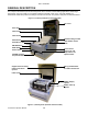
Unit 1: Introduction GENERAL DESCRIPTION The compact CT4xxi Series printers are designed for use in medium-volume labeling applications demanding a low footprint, crisp print quality of up to 600dpi; hardware versatility, ease of use, and great reliability. Its antibacterial chassis also positions it ideally for clinical environments. The printer’s main parts are described below.
Unit 1: Introduction This page is left blank intentionally.
Unit 2: Technical Data TECHNICAL DATA • • • • • • • • • • • • • CT4i Series Operator Manual Physical Characteristics Environmental Specs Power Supply Processing Printer Language Interface Modules Print Sensing Media Ribbon Regulatory Approvals Character Font Capabilities Barcode Capabilities 2-1
Unit 2: Technical Data PHYSICAL CHARACTERISTICS Width 7.8 in. (198 mm) Height 8.8 in. (225 mm) Depth 7.1 in. (180 mm) Weight 5.5 lbs (2.5 Kg) excluding AC adaptor ENVIRONMENTAL (EXCLUDING MEDIA) Operating Temperature/Humidity Storage Temperature/Humidity 5° to 35°C @ 30 to 80%RH -5° to 60°C @ 30 ~ 90%RH, non-condensing (NA for media) POWER SUPPLY Input Voltage (AC) 100-240 Volts AC +/- 10%, 50/60 Hertz Rated Input voltage: 25 V DC Rated current: 1.5 A Input Voltage (DC) Rated voltage: 24.
Unit 2: Technical Data PRINT Method Maximum Speed (selectable) Resolution DT models: Direct Thermal only TT models: Thermal Transfer and Direct Thermal (switchable) 2, 3, 4, 5, 6 Inches Per Second (CT408i) 2, 3, 4 Inches Per Second (CT412i) 2, 3 Inches Per Second (CT424i) CT408i: 203 Dots Per Inch (8 dpmm) CT412i: 305 Dots Per Inch (12 dpmm) CT424i: 609 Dots Per Inch (24 dpmm) Maximum Print Width 4 in. (104 mm) Maximum Print Length 15.75 in.
Unit 2: Technical Data REGULATORY USA/Canada UL60950-1(2001), CSA C22.2 No.60950-1-03 China CCC (GB4943-2001) EU CE, Nemko (EN60950-1) Singapore SS337:2001 Korea MIC, EK (only AC-Adapter applicable) FCC Part 15, Subpart B, Class B (USA/Canada) GB9254-1998, GB17625.1-2003 (China) CE (EN55022, EN55024, EN61000-3-2/-3) (EU) CISPR22, CISPR24 (reference standard, Singapore) KN22, KN24 (Korea) Radiation Noise WLAN/RFID/Bluetooth FCC15B / FCC15C (USA/Canada) SRRC (China) Wireless LAN/Bluetooth (2.
Unit 2: Technical Data BARCODE CAPABILITIES Linear Bar Codes UPC-A/E, EAN, CODABAR, CODE39, CODE93, CODE128, UCC/EAN128, Interleaved 2of5, Industrial 2of5, Matrix 2of5, MSI, BOOKLAND, POSTNET, EAN/UCC symbol Two Dimensional QR code (Ver8.1), PDF417 (Ver2.4), MAXI code (Ver3.0), Data Matrix (Ver1.
Unit 2: Technical Data INTERFACE SELECTION This unit presents the printer interface types and their specifications. These specifications include detailed information to assist in the selection of the most appropriate method for the printer to interface with the host. The five acceptable interface methods are: • • • • • • RS232C High-Speed Serial IEEE1284 Parallel Universal Serial Bus (USB) Bluetooth Local Area network (LAN) Ethernet 802.
Unit 2: Technical Data I/O SIGNALS PIN# SIGNAL I/O DESCRIPTION 1 FG - Framework Ground 2 SD Output Data transferred from Printer to Host 3 RD Input Data transferred from Host to Printer 4 RS Output Goes to the Low state when an error occurs in the printer 5 CS Input Maintained at the High state 6 DR Input Maintained at the High state 7 SG - Signal Ground 20 ER Output Goes to the High state when printer is ready to receive data Goes Low when printer is OFFLINE or errors ha
Unit 2: Technical Data IEEE1284 PARALLEL INTERFACE The parallel interface is a plug-in module that can be installed by the user and conforms to IEEE1284 specifications. It automatically detects the IEEE1284 signals and operates in the high speed mode. If the IEEE1284 signals are not detected, it will operate in the slower standard Centronics mode. For this reason, an interface cable and host interface conforming to the IEEE1284 specification must be present to fully utilize the speed capabilities.
Unit 2: Technical Data UNIVERSAL SERIAL BUS (USB) The Universal Serial Bus (USB) interface is a Plug-In Interface Module that can be installed by the user. It requires a driver (shipped with each printer that has the interface installed) that must be loaded onto the PC and configured to support USB peripherals using Windows 2000 or above. Details for loading the USB driver are contained in the USB Interface Manual that is shipped with each printer with a USB Optional interface installed.
Unit 2: Technical Data SPECIFICATIONS Connector RJ-45 Receptacle Cable 10/100BaseT Category 5 Cable Length 328 ft. (100 meters) or less Power Supply Powered from printer Protocol Status3 return Protocol for Driver (cyclic response mode) Protocol for Driver (ENQ response mode) Status5 return IP Address 0.0.0.0 to 255.255.255.255 Subnet Mask 0.0.0.0 to 255.255.255.255 Gateway Address 0.0.0.0 to 255.255.255.255 802.
Unit 2: Technical Data LED INDICATOR STATUS Wireless LED (green) Front Panel Blinking On Ad-hoc mode Infrastructure mode WIRELESS LAN SIGNAL STRENGTH Off Network Port Link LED 0 to 50% (weak) Blinking 50 to 75% (medium) On 75 to 100% (strong) SOFTWARE SPECIFICATIONS Corresponding Protocol TCP/IP Network Layer ARP, RARP, IP, ICMP Session Layer TCP, UDP Application Layer LPD, FTP, TELNET, BOOTP, DHCP NOTE: Print data can be sent by LPR and FTP of TCP/IP and dedicated socket protocol.
Unit 2: Technical Data Figure 3-7, Socket Connection Diagram CT4i Series Operator Manual 2-12
Unit 2: Technical Data ALL INTERFACES Receive Buffer The data stream is received from the host to the printer one job at a time. This allows the software program to maintain control of the job print queue so that it can move a high priority job in front of ones of lesser importance. A multiple job buffer allows the printer to continuously receive print jobs while compiling and printing other jobs at the same time. It acts much like a Print buffer to maximize the performance of the host and the printer.
Unit 2: Technical Data STATUS5 TIMING CHARTS NORMAL PROCESS (Figure 3-8a) CANCEL PROCESS (Figure 3-8b) ERROR PROCESS (Figure 3-8c) CT4i Series Operator Manual 2-14
Unit 2: Technical Data STATUS5 TIMING CHARTS PRINT PROCESS (Figure 3-8d) COMMAND PROCESS (Figure 3-8e) BCC ERROR PROCESS (Figure 3-8f) CT4i Series Operator Manual 2-15
Unit 2: Technical Data This page is intentionally left blank.
Unit 3: Installation INSTALLATION • • • • • CT4i Series Operator Manual Unpacking & Parts Identification Printer Installation Operational Mode Selection Interface Selection Accessories Installation 3-1
Unit 3: Installation OVERVIEW This section assists you in unpacking the printer from the shipping container. You will also be guided through a familiarization tour of the main parts and controls.
Unit 3: Installation SAFETY PRECAUTIONS Please read the following information carefully before installing and using the printer THE CAUTION SYMBOL Whenever the triangular Caution logo appears in this manual, pay special attention to the warning(s) cited below it. Failure to abide by the warnings may result in injury or damage to property. PRINTER PLACEMENT TIPS • Place the printer on a solid, stable, horizontal surface that is not subject to strong vibrations from adjacent mechanical devices.
Unit 3: Installation GENERAL PRECAUTIONS • When using head cleaning liquid, note that it is flammable. Never heat it or throw it into a fire. Keep it out of children’s reach to avoid accidental consumption. Should this occur, consult a doctor immediately. • When opening/closing the cover, beware of getting your fingers caught. Also, hold the opening/closing cover well so that it will not slip and fall onto the hand. • After printing, the print head remains hot.
Unit 3: Installation UNPACKING & PARTS IDENTIFICATION When unpacking the printer, take note of the following: 1 The box should stay right-side up. Lift the printer out of the box carefully. 4 If the printer has been stored in the cold, allow it to reach room temperature before turning it on. 2 Remove the plastic covering from the printer. 5 Set the printer on a solid, flat surface. Inspect the shipping container and printer for any sign of damage that may have occurred during shipping.
Unit 3: Installation PRINTER INSTALLATION This chapter provides guidance on how to station, connect, and load the printer once unpacked. Following printer setup, proceed to the next chapter for information on interface selection. SITE LOCATION • Station the printer on a solid flat surface. • Station it away from hazardous materials or dusty environments.
Unit 3: Installation RIBBON LOADING This chapter provides guidance on how to station, connect, and load the printer once unpacked. Following printer setup, proceed to the next chapter for information on interface selection. 1 3 2 Ribbon Supply Spindle Get the media ready. The label roll is optional in this procedure. Raise the ribbon loader assembly as shown here. Load the ribbon roll (shiny side up) into the supply spindle from underneath (see blue arrow).
Unit 3: Installation LOADING FANFOLD PAPER Fan-folded media is fed inward from the rear, via the rear housing cover (highlighted in yellow below), but is stacked as opposed to suspended. Ribbon can be wound in or wound out. 1. Place the fanfold media behind the printer with the printing surface up. 2. Carefully pull up the Fanfold-label Loading Slot from the back of the Top Cover. 3. Open the Top Cover by pressing on the cover release latch located on the right-hand side of the printer.
Unit 3: Installation LABEL SENSING The SATO CT4xxi uses label Gap (see-thru) sensing. The Sensor Assembly is located on the left edge of the media and is automatically positioned by the Paper Guides. Printer Label Sensor Positioning Inter-label gap: Min: 0.12” (3 mm) Max: 0.
Unit 3: Installation OPERATIONAL MODE SELECTION There are two modes of printer operation; Dispense and Continuous. The difference between the two is the way that the label and paper backing is ejected. Before printer configuration, one must determine which mode will be used. This chapter identifies the functional differences between the two. ATTENTION: Refer to the Printer Configuration unit of this manual to program the printer’s internal memory to suit individual needs using the integrated menu options.
Unit 3: Installation CONTINUOUS MODE TRANSMISSION SENSOR REFLECTIVE SENSOR Base Print Position TEAR-OFF MODE TRANSMISSION SENSOR REFLECTIVE SENSOR Base Print & TearOff Position CUTTER MODE REFLECTIVE SENSOR Base Print Position Base Print Position Base Print & Cut Position DISPENSE MODE REFLECTIVE SENSOR TRANSMISSION SENSOR Base Print Position Base Dispense Position Base Print & Dispense Position LINERLESS MODE REFLECTIVE SENSOR Base Print Position Base Cut Position Figure 3-4, Label Referenc
Unit 3: Installation This page is intentionally left blank.
Unit 4: Printer Configuration PRINTER CONFIGURATION • • • CT4i Series Operator Manual Configuration Modes Configuration Modes Menu Definition Tables 4-1
Unit 4: Printer Configuration CONFIGURATION MODES Before using the printer, read this manual thoroughly first. Otherwise, you may disturb default settings upon which the instructional procedures in this manual are based. The printer may be configured via the buttons and/or potentiometers located on the printer’s front panel. All of the printer’s buttons, switches, and potentiometers are used either singularly, or in conjunction, to perform configuration activities. 4.
Unit 4: Printer Configuration 4.2 THE REAR PANEL All of the printer cable connectors are located on the Rear Panel, as follows.
Unit 4: Printer Configuration 4.3 THE CONFIGURATION PANEL The Configuration Panel is accessible when you lift up the top cover. The panel consists of an eight-position DIP switch, three adjustment potentiometers and a sevensegment LED Error Status display. Receptacles for connecting the optional Cutter (factory installed) are also located on this panel.
Unit 4: Printer Configuration 4.3 DIP SWITCH SETTINGS (CONT’D) Switches 1–3: Font/Graphic loading settings Enables the loading of fonts and/or graphics into printer memory for faster retrieval. DSW1 DSW2 DSW3 Off On Mode On Load Font Configuration Switch ON OFF 1 Switch 4: DT/TT Mode Switches the printer between Direct Thermal (DT) or Thermal Transfer (TT).
Unit 4: Printer Configuration Switch 6: VR1 Potentiometer Adjustment mode Selects the function adjusted by VR1. If DSW6 is Off, VR1 adjusts the pitch offset value over a range of +/- 3.75 mm. When DSW6 is On, VR1 adjusts the print darkness range. DSW6 Mode Off Pitch Offset On Print Darkness Configuration Switch ON OFF 1 Switch 7: DATA Dump When ON, the printer will print out the hex value for each character received.
Unit 4: Printer Configuration 4.4 OPERATIONAL MODES The CT4xxi operates in 10 different modes, where each mode can by invoked via combinations of pressing the front panel buttons in a certain sequence together with DIP switch settings and print head status. The table below lists all the modes and how they can be invoked.
Unit 4: Printer Configuration 4.4 OPERATIONAL MODES (CONT’D) Following are the standard operational functions and procedures available for selected modes. Modes not covered here are covered in the Service Manual. 4.4.1 Normal Mode The printer normally starts up in this mode. It automatically goes ONLINE and is ready for printing jobs. The following operations are possible: • Pressing the ONLINE button repeated takes the printer to ONLINE or OFFLINE mode alternately.
Unit 4: Printer Configuration 4.4.2 User Test Print Mode (FEED + POWER ON) This mode produces test labels for diagnostic purposes. Upon entering this mode on startup, release the FEED button. A beep is then produced, and the ERROR LED will light up. When labels have been loaded properly, press the ONLINE or FEED button to start printing. Pressing the FEED button produces small test label data, while the ONLINE button produces a big test print. The ERROR LED goes off during the test printing.
Unit 4: Printer Configuration 4.4.3 Default Settings Mode (ONLINE + FEED + POWER ON) Turning the printer ON in this mode simply resets major settings to their default values. (See table). After the default values have been restored, the printer emits three beeps. The ERROR LED also lights up during the reset operation, but goes off after the settings have been activated.
Unit 4: Printer Configuration 4.4.4 HEX Dump Mode (POWER ON with DSW7=ON) When turned ON in this mode, the printer will print a dump of its buffer contents received for the host. The printer awaits data feeds and when data arrives, it prints out the HEX data continuously. To terminate the HEX Dump, set DSW7 to OFF and restart the printer. 4.4.
Unit 4: Printer Configuration 4.4.6 Program Download Mode (DSW1=ON, DSW2=OFF, DSW3=ON + POWER ON) In this mode, the printer is set to receive an application program from the host computer to download into its memory. Remember to set the printer to the correct active interface to be used for the data transfer.
Unit 4: Printer Configuration 4.4.8 Errors during Font and Program Download Modes • Possible causes of errors could be that the data transfer is not correct between the printer and host, due to interface setting incompatibilities or faults in the cable. The flash ROM may be in a state that does not permit data being written to it.
Unit 4: Printer Configuration 4.9 OFFSETS There are two offset settings stored in the printer; one for the Cut mode and one for the Tear-Off mode. These two offsets can be set independently and will remain in the printer until a new command is received changing the setting or until power is turned off. The default settings can be determined by printing a User Test Label.
Unit 4: Printer Configuration 4.10 POTENTIOMETER ADJUSTMENTS PITCH OFFSET This can be done using the VR1 potentiometer on the Configuration Panel. This potentiometer is set at the factory so that it has a range of +/- 0.15” (3.75 mm). The midpoint setting should have no effect on the label pitch. Turning the potentiometer all the way clockwise should move the print position 0.15” (3.75 mm) upward toward the leading edge of the label.
Unit 4: Printer Configuration 4.10 POTENTIOMETER ADJUSTMENTS (CONT’D) Print Darkness A fine adjustment for PRINT DARKNESS can be made using potentiometer VR1 on the Front Operator Panel. It provides a continuous range of adjustment, allowing you to make precise changes. Turning VR1 clockwise will make the print darker, and counterclockwise will make it lighter. 1. Place DSW6 on the Configuration Switch in the ON position. 2. Turn the Power Switch OFF. 3.
Unit 4: Printer Configuration 4.11 DATA DUMP DIAGNOSTIC LABEL The contents of the printer buffer can be examined using the DATA Dump mode. This printout labels each line of the received data in the left hand column, the data in the middle column followed by the same data in ASCII format in the right-hand column. 1. Turn the printer OFF. 2. Place DSW7 on the configuration Switch in the ON position. 3. Turn the printer ON. 4. Transmit data to the printer. 5. The data received is printed on the label. 6.
Unit 4: Printer Configuration 4.12 PRINTING TEST LABELS 1. The User Test Label prints the current default settings of the printer. 2. Press the FEED button while turning the power ON. 3. When the printer beeps, release the FEED button. 4. To print a large (4" wide) test label, press the ON LINE button. To print a small (2" wide) test label, press the FEED button. 5. The printer will continuously print the USER TEST LABEL until the FEED button is pressed.
Unit 4: Printer Configuration 4.13 PRINTING FACTORY/SERVICE TEST PRINTS The Factory/Service Test Label prints the internal operating parameters of the printer. 1. Release the print head. (see “Releasing/Replacing the Print Head“” on page 3). 2. Press the LINE and FEED buttons while turning the printer ON. 3. When the printer beeps, release the LINE and FEED buttons. The printer will then beep 3 times indicating it is in the Factory/Service Print Test mode. 4. Re-latch the Print Head. 5.
Unit 4: Printer Configuration CT4i Series Operator Manual 4-20
Unit 5: Troubleshooting TROUBLESHOOTING • • • CT4i Series Operator Manual Troubleshooting Guide Interface Troubleshooting Test Print Troubleshooting 5-1
Unit 5: Troubleshooting TROUBLESHOOTING GUIDE Display ON ERROR BUZZER 0 ON 1 Beep 1 ERROR CONDITION Flash Memory error CORRECTIVE ACTION Consult your SATO dealer Not Assigned 2 ON 1 Beep Machine Error Consult your SATO dealer 3 ON 1 Beep EEPROM Error Replace EEPROM 4 ON 1 Beep Electrical Head error Replace Print Head or consult your SATO dealer 5 Blink 3 Beeps Head Not Latched Latch Print Head securely and make sure the Top Cover is closed properly 6 Blink 3 Beeps Out of Pa
Unit 5: Troubleshooting Display ON ERROR BUZZER L blinks No beep steady long beep ERROR CONDITION Low Battery level Critically Low Battery level CORRECTIVE ACTION Check the battery level and recharge or replace the battery as necessary Replace or recharge the battery y USB interface selected NA l Other interface selected NA CT4i Series Operator Manual 5-3
Unit 5: Troubleshooting TROUBLESHOOTING TABLE IMAGE VOIDS Dirty print head Clean print head Damaged print head Replace print head Damaged electronics Replace circuit board Damaged or worn roller Replace rollers Poor label quality Use higher quality media Ribbon stock and media are mismatched Consult with media supplier.
Unit 5: Troubleshooting NO PRINTED IMAGE Print head is disconnected. Ensure print head wiring harness is connected on each end. No voltage output Replace fuse.
Unit 5: Troubleshooting INTERFACE TROUBLESHOOTING This chapter provides a checklist for the various interface types. Locate the checklist relative to the interface used and perform each of the troubleshooting tasks until the problem has been isolated. PARALLEL INTERFACE CHK TROUBLESHOOTING STEP Ensure the interfaces or interface card are correctly installed. Run self-test to verify. Ensure the printer cable is connected to the appropriate LPT port on the host computer.
Unit 5: Troubleshooting LAN ETHERNET INTERFACE CHK TROUBLESHOOTING STEP Ensure the interface has been correctly configured. Wait two minutes and run self-test to verify. If a test label does not print, there may be a hardware problem. Ensure the cable and its ports are not defective. Ensure that a faulty print server or other protocol related scenarios are not creating a queue setup issue. Systematically perform checks and tests to isolate the cause.
Unit 5: Troubleshooting TEST PRINT TROUBLESHOOTING Chapter provides instruction on special printing to identify and resolve specific print problems. HEX DUMP Allows the operator to determine if there were problems in the downloading of data. The contents of the print buffer can be examined using the Hex Dump Mode. In the left column, each line of data received is numbered. The center column provides the data in hexadecimal format. And in the right column, same data is provided in the ASC ll format.
Unit 6: Maintenance MAINTENANCE • • • CT4i Series Operator Manual Cleaning Procedures Replacement Procedures Adjustment Procedures 6-1
Unit 6: Maintenance CLEANING PROCEDURES Cleaning of the printer is a necessary maintenance activity to ensure print quality and longer printer life. There are two basic types of cleaning involved; the removal of loose debris and the removal of residue. Use a soft cloth and/or a pneumatic blower to remove debris from the printer. This process should be performed prior to the removal of residue.
Unit 6: Maintenance ADJUSTMENT PROCEDURES This section provides information on user maintenance for the SATO Ct4xxi printer. This section contains the following information. • Adjusting the Print Quality • Cleaning the Print Head, Platen and Rollers • Replacing the Print Head ADJUSTING THE PRINT QUALITY The SATO CT4xxi printer is equipped with two different methods of adjusting the quality of the print— print darkness and print speed.
Unit 6: Maintenance CLEANING THE PRINT HEAD, PLATEN AND ROLLERS Cleaning the Print Head 1. Before starting, get ready an approved cleaning kit from your SATO dealer or the kit supplied with the printer. Make sure the printer is OFF, and remove the power cable. 2. Lift up the Top Cover and locate the Print Head Assembly which is mounted under the cover. 3. Apply Thermal Print Head Cleaner to a cotton swab. 4. The Print Head faces downward along the front edge of the assembly.
Unit 6: Maintenance CLEANING THE PRINT HEAD, PLATEN AND ROLLERS (CONT’D) Cleaning the Platen and Paper Roller 1. Before starting, get ready an approved cleaning kit from your SATO dealer or the kit supplied with the printer. Make sure the printer is OFF, and remove the power cable. 2. Lift up the Top Cover. 3. The platen roller is the black rubber roller near the front panel. The print rollers are located at the print head assembly, near the fanfold-label loading window. 4.
Unit 6: Maintenance RELEASING/REPLACING THE PRINT HEAD The print head on the printer is a user-replaceable item. If it becomes damaged for any reason, it can be easily removed and replaced. Contact your local SATO representative for information on obtaining a new print head. You will also need a No. 2 Phillips screwdriver (a magnetic tip is helpful) for the replacement procedure. 1. Make sure the printer is OFF, and remove the power cable. 2. Lift up the Top Cover. 3.
Unit 6: Maintenance CLEANING THE SENSOR The gap sensor is used to control the positioning of the label. It is a transmissive see-thru sensor that detects the edge of the label by sensing through the backing paper which is translucent and detecting the presence of the opaque label. So when dust, dirt or other foreign matter interferes with the light path of the sensor, erratic label positioning occurs. The sensor should thus be cleaned regularly, after every two rolls of labels. 1.
Unit 6: Maintenance CT4i Series Operator Manual 6-8
Section 7: SATO Group of Companies SATO GROUP OF COMPANIES CT4i Series Operator Manual Page 7-1
SATO GROUP OF COMPANIES Asia Pacific & Oceania Region SATO ASIA PACIFIC PTE. LTD. 438B Alexandra Road #09-01/02, Alexandra Technopark, Singapore 119968 Tel: +65-6271-5300 Fax: +65-6273-6011 Email: technical@satoasiapacific.com www.satoasiapacific.com SATO AUTO-ID MALAYSIA SDN. BHD. SATO ASIA PACIFIC PTE. LTD. in Ho Chi Minh City Vietnam Representative Office Level 6, Room 615.