RFID KIT INSTALLATION GUIDE For printer models: GL 4XXe Series For printer models: Read this Installation Guide before and during the installation of the above accessory. Keep this Installation Guide handy for future reference.
1 General 1.1 Important information This quick guide provides important information on how to setup your new SATO product. Be sure to read this quick guide thoroughly before using this printer. It is an integral part of the product and should be kept in the immediate vicinity of the device and available to the operating staff. 1.2 Limitation of liability All information in this manual have been compiled under due consideration of federal standards and regulations.
1.3 Explanation of symbols This instruction manual uses various warning icons to help you understand the safe operation of your printer. Explanations of the icons are below. WARNING! Indicates neglectful or erroneous use may cause irreparable damage to the product, serious injury to the operator, or worse. CAUTION! Indicates a specific point where caution should be used. The graphic within the triangle will indicate the specific issue, i.e.
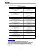
1.4 Contact and Document Information SATO GROUP OF COMPANIES . International Headquarters Americas SATO INTERNATIONAL PTE. LTD 438A Alexandra Road #05-01/04, Alexandra Technopark, Singapore 119967 Phone: 65-6271-2122 Fax : 65-6271-2151 Email: sales@sato-int.com SATO INTERNATIONAL AMERICA, INC. (Regional HQ) 10350 Nations Ford Road Suite A, Charlotte, NC 28273 Phone: 1-704-644-1650 Fax: 1-704-644-1662 Email: satosales@satoamerica.com Americas SATO LABELING SOLUTIONS AMERICA, INC.
GL4xxe RFID KIT Installation The complete RFID kit for the GL consists of five (5) parts: Four parts from the main RFID kit and one part containing the RFID Reader module from AWID. All five parts must be available before installation. Installation involves five (5) steps: Removing the covers; removing the print head; installing the antenna and Reader, and general reassembly.
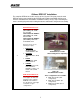
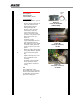
Removing the front cover Tool(s) required Flat blade screwdriver (recommended) 1. Loosen and remove the thumbscrew fastener that secures the front cover. Figure 1a. Removing the thumbscrew 1 2. Pull the outer edge of the front cover outwards, and then push the entire cover in the direction shown by the arrow. The cover will be dislodged. 3. Put the cover and thumbscrew aside. Figure 1b.
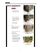
Removing the Print Head 2 1. Release the print head assembly by turning the head lock latch counterclockwise. 2. Press the spring-loaded tab as indicated here, to release the print head. 3. Disconnect the data and power cables from the print head. 4. Figure 2a. Turning the head lock latch Set the print head aside for now. Note: ESD (electrostatic discharge) protection is recommended for this step. Anti-static lint-free gloves should be worn at all times when you are handling print heads.
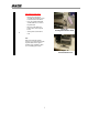
Installing the antenna Part(s) Required ANTENNA ASSY, RFID, SL4M SCREW, 6-19 HL X 1/2, PHCR, SS410, ANSI B18.6.4 Tool(s) required #1 Phillips + screwdriver - 12 in. lb 1. Remove the gap sensor paddle (circled red) by sliding it out. Set the gap sensor paddle aside for later use. 2. Remove the media guard (circled yellow) that is under the gap sensor, by removing the associated screw (circled blue). (Figure 3a) 3.
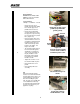
Assembling the Reader Module Antenna cable Parts required READER MOUNT SUBASSEMBLY, GL4xxe Tool(s) required #1 Phillips + screwdriver - 8 in. lb. 1. Plug the antenna cable into the port on the right side of the Reader Subassembly as indicated in Figure 4a. Figure 4a. Ports on the Reader Subassembly. 2. Route the other end of the cable into the electronics section of the printer. The cable connects to the white connector on the printer’s main PCB, near the moto. See Figure 4c. 3.
Reassembly Tools required #1 Phillips + screwdriver - 8 in. lb. 1. Pull any slack interface cable slack back into the electronics compartment of the printer. 2. Put back the side cover that was removed in Step 3 (page 6). 3. Tighten and torque screws. 4. Put back the front cover that was removed in Step 2. 5. Re-install the gap sensor paddle in the reverse order of removal. 6. Close the media cover.