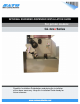
INTERNAL REWINDER-DISPENSER INSTALLATION GUIDE For printer models: GL 4xxe Series Read this Installation Guide before and during the installation of the above accessory. Keep this Installation Guide handy for future reference.
1 General 1.1 Important information This quick guide provides important information on how to setup your new SATO product. Be sure to read this quick guide thoroughly before using this printer. It is an integral part of the product and should be kept in the immediate vicinity of the device and available to the operating staff. 1.2 Limitation of liability All information in this manual have been compiled under due consideration of federal standards and regulations.
1.3 Explanation of symbols This instruction manual uses various warning icons to help you understand the safe operation of your printer. Explanations of the icons are below. WARNING! Indicates neglectful or erroneous use may cause irreparable damage to the product, serious injury to the operator, or worse. CAUTION! Indicates a specific point where caution should be used. The graphic within the triangle will indicate the specific issue, i.e.
1.4 Contact and Document Information SATO GROUP OF COMPANIES . International Headquarters Americas SATO INTERNATIONAL PTE. LTD 438A Alexandra Road #05-01/04, Alexandra Technopark, Singapore 119967 Phone: 65-6271-2122 Fax : 65-6271-2151 Email: sales@sato-int.com SATO INTERNATIONAL AMERICA, INC. (Regional HQ) 10350 Nations Ford Road Suite A, Charlotte, NC 28273 Phone: 1-704-644-1650 Fax: 1-704-644-1662 Email: satosales@satoamerica.com Americas SATO AMERICA, INC.
GL4xxe Internal Rewinder-Dispenser Installation The installation procedure for the Internal Rewinder with front-mounted dispenser, involves three major steps, that are similar to the installation of the GL4xxe internal rewinder: 1) Removing the base of the printer. 2) Mounting the printer above the rewinder and reinstallation of all removed covers. 3) Mechanical adjustment of the rewinder.
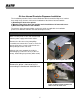
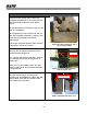
1) Removing the base of the printer (cont’d) The front cover can now be removed. Figure 1c. Front cover can now be removed Remove the lock shaft located at the front of printer. (Do not lose this part as it is essential for the installation of dispenser option) Note This lock shaft must be removed for the successful installation of the internal rewinder. Figure 1d. Removing the lock shaft. Remove a total of 9 screws (cross recessed hexagonal bolt M4x10). Four screws are circled in orange in Figure 1d.
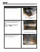
1) Removing the base of the printer (cont’d) The fifth screw to be removed is shown here. Figure 1e. Removing the fifth of nine screws The sixth and seventh screws are shown here, securing the base to the front of the chassis. Figure 1f. Removing the sixth and seventh screws The last two screws are on the electronic section as circled here in orange. Figure 1g.
1) Removing the base of the printer (cont’d) Finally, carefully separate the base plate of the printer from the main chassis. This can be done by placing the printer on its side and pulling the base plate out. Figure 1h.
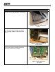
2) Mounting the printer above the rewinder-dispenser To facilitate easier mounting, it is recommended that you remove the front cover of the internal rewinder-dispenser beforehand. Front cover フロントカバー Pull down the side cover of the internal rewinder and remove two bind screws (M4x4) located as shown within the orange circles. 図 Side cover Figure 2a. Removing the rewinder’s front cover Remove two bind screws (M4x4) located as shown within the orange circles.
1) Mounting the printer above the rewinder A total of seven screws (cross recessed hexagonal bolt M4x10) are used to install the internal rewinder-dispenser to the printer chassis (Do not damage the PCB when using any tool such as screwdriver) Do not tighten all seven screws until you are sure the installation alignment is correct. Also check that all connectors have been reconnected. Two screws removed originally from the front of the printer, will be left unused. Figure 2d.
1) Mounting the printer above the rewinder (cont’d) If the front cover snaps into place correctly, you can proceed to further tighten the screws permanently, followed by inserting the thumbscrew used to secure the printer’s front cover in the first step of this guide. Figure 2g. Installing the thumbscrew Finally, connect the printer power cable as shown, routing it through the slot at the bottom of the internal rewinder. Figure 2h.
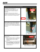
3) Mechanical adjustment of the dispenser Turn the printer ON and take it OFFLINE (by pressing the LINE button). ADVANCED MODE Go into the printer’s ADVANCED Mode and scroll to the Media Handling menu. Select Peel-Off to activate the peel-off and rewinder functions, and then exit the menu. Perform some printing to test the proper functioning of the liner rewinder. Use the Media Handling menu to activate the rewinder Peel-Off Figure 3a.