
Instruction manual

Section 3: Operation and Configuration
GY412 Operator Manual Page 3-89
3.3 LCD MESSAGE DETAILS (cont’d)
3.3.1.16 Test Print Mode
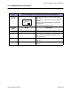
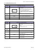
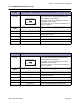
Display Test Print Mode - Adjustment of print position on the upper surface
Onscreen
message
Adjusting the print position on the upper surface.
Use ↑ and ↓ keys to change setting value and
press ENTER to start test print.
The setting value can be adjusted by ±0.25mm
regardless of print density.
The setting range is ±3.75mm and the default set-
ting is “+0.00”mm.
Operation
button
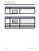
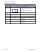
Button Description
↓, ↑ Enters setting value by ±0.25mm.
←, → Toggles the screens.
ENTER Starts test print.
CANCEL Goes to the [TEST PRINT SIZE] screen.
FUNCTION Goes to the [MAINTENANCE MODE] screen.
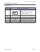
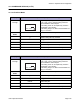
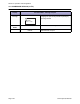
Display Test Print Mode - Adjustment of print position on the lower surface
Onscreen
message
Adjusting the print position on the upper surface.
Use ↑ and ↓ keys to change setting value and
press ENTER to start test print.
The setting value can be adjusted by ±0.25mm
regardless of print density.
The setting range is ±3.75mm and the default set-
ting is “+0.00”mm.
Operation
button
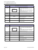
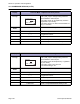
Button Description
↓, ↑ Enters setting value by ±0.25mm.
←, → Toggles the screens.
ENTER Starts test print.
CANCEL Goes to the [TEST PRINT SIZE] screen.
FUNCTION Goes to the [MAINTENANCE MODE] screen.
PITCH POSITION UPPER
+0.00
ENTER -> PRINT
PITCH POSITION LOWER
+0.00
ENTER -> PRINT