® M-8485Se Standard OEM Print Engine Service Manual PN 9001080 Rev.
SATO America, Inc. 545 Weddell Drive Sunnyvale, CA 94089 Main Phone: (408) 745-1300 Tech Support Hotline: (408) 745-1379 Fax: (408) 745-1309 http:\\www.satoamerica.com Copyright 2000 SATO America, Inc. The information supplied in this manual was current at time of publication. If you come across procedures that need clarification or find errors or have suggestions contact us at qc@satoamerica.
Section Overview and Specifications 1.1 Overview The SATO M-8485Se Service Manual provides information for installing and maintaining M-8485Se Thermal Transfer Print Engines. Step-by-step maintenance instructions are included in this manual with typical problems and solutions. It is recommended that you become familiar with each section in this manual before installing and maintaining the printer.
Section 1. Overview and Specifications 1.2 Dimensions and Power Requirements DEEP WIDE HIGH SPECIFICATION M-8485Se DIMENSIONS Wide 10.4 in. (264 mm) D eep 16.1 in. (410 mm) High 11.8 in. (300 mm) Weight 25.0 lbs (11.34 Kg) POWER REQUIREMENTS Voltage Power Consumption Page 1-2 115 - 220 V (+/- 10%) 50/60 Hz (+/- 1%) 50W Idle 700W Operating SATO M-8485Se Standard Print Engine Service Manual PN 9001080 Rev.
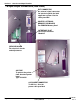
Section 1. Overview and Specifications 1.3 Components DIP SWITCH PANEL DIP SWITCH CONFIGURATION TABLE OPERATION PANEL RIBBON UNWIND RIBBON REWIND RIBBON LABEL EDGE GUIDE PEEL BAR PLATEN ROLLER MEDIA HOLD DOWN HEAD PRESSURE ADJUST MEDIA OUT HEAD LOCK LEVER NIP ROLLER LATCH PN 9001080 Rev.
Section 1. Overview and Specifications Components FRONT COVER DISPLAY PANEL PC BOARD MAIN PC BOARD RIBBON MOTOR PRINT HEAD POWER SUPPLY PRINT HEAD NIP ROLLER ASSEMBLY (COVERS THE REAR PLATEN) Page 1-4 PLATEN ROLLER PEEL BAR SATO M-8485Se Standard Print Engine Service Manual PN 9001080 Rev.
Section 1. Overview and Specifications 1.4 Operation Panel CONTROL KEYS & INDICATORS POWER ON/OFF SWITCH LCD DISPLAY OPERATION PANEL LCD Display LABEL LED RIBBON LED ERROR LED ON-LINE LED LINE KEY FEED KEY 2 Line x 16 Character display Illuminated when label is out Illuminated when ribbon is out Illuminated when errors have occurred Illuminated when printer is On-Line Switches the printer On-Line or Off-Line. Can also be used as a Pause function key to stop label during the printing process.
Section 1. Overview and Specifications 1.6 Input/Output Connections (Rear Panel) EXT CONNECTOR An external signal connector for interfacing with the label applicator system. Use the cable provided.
Section 1. Overview and Specifications 1.7 Switches and Sensors 2 3 1 5 (IN TOP LID) 4 ITEM PN 9001080 Rev.
Section 1. Overview and Specifications Switches and Sensors 2 1 3 4 5 Page 1-8 6 SATO M-8485Se Standard Print Engine Service Manual PN 9001080 Rev.
Section 1. Overview and Specifications 1.8 Adjusting the Label Sensor The label gap (transmissive) sensor can be positioned over a limited range. The movable sensor assembly is mounted on the Label Hold Down and is held in position by two screws. To adjust the position of the sensor, both screws must be loosened and the sensor moved to the desired position in the slot and then the screws retightened. Adjustments to compensate for different liner opacity are done with the LCD panel.
Section 1. Overview and Specifications Adjusting the Label Sensor INSIDE LABEL EDGE INSIDE FRAME The M-8485Se printers can position labels using either a label gap (transmissive) or an "EyeMark" (reflective) sensor. The sensor used is selected by DSW2-2. The gap sensor position can be adjusted over a limited range. In addition, the signals from the sensors can be adjusted using the LCD panel to compensate for different liner opacities and/or "Eye-Mark" reflectance values.
Section 1. Overview and Specifications 1.9 Ribbon Use only SATO thermal transfer ribbons which were formulated expressly for use in all SATO printers. Use of other than approved ribbons may result unsatisfactory print quality and/or damage to the print head and may void your warranty. 1.10 Installation Considerations Printer operation can be affected by the printer environment. The location of the printer should be free from dust, humidity and sudden vibrations.
Section 1. Overview and Specifications 1.11 General Printer Specifications SPECIFICATION M-8485Se PRINT Method Direct or Thermal Transfer 4 to 12 ips 100 to 300 mm/s Speed (User Selectable) Print Module (Dot Size) .0049 in. .125 mm Resolution 203 dpi 8 dpmm Maximum Print Width 5.0 in. 128 mm 1024 dots Maximum Print Length 49.2 in. 1249 mm MEDIA Minimum Width 1.0 in. (25 mm) Minimum Length .25 in. (6 mm) Maximum Width 5.
Section 1.
Section 1.
Section 1. Overview and Specifications 1.
Section 1. Overview and Specifications 1.
Section 2 Configuration 2.1 Dip Switch Settings Two DIP switches (DSW2 & DSW3) are located inside the cover. These switches can be used to set: • Thermal transfer or direct thermal mode • Head Check Mode • Hex Dump Mode • Label sensor enable/disable • Single Job or Multi-Job Receive Buffer • Operation Mode DIP SWITCHES In addition, a third DIP switch (DSW1) is located on the RS232 Serial Adapter card and is used to set the RS232C transmit/receive parameters.
Section 2. Configuration Dip Switch Settings RS232 Transmit/Receive Setting (Located on RS232 I/F Module) Data Bit Selection (DSW1-1): This switch sets the printer to receive either 7 or 8 data bits for each byte transmitted. DSW1 DSW1-1 SETTING ON Off 8 data bits On 7 data bits OFF 1 2 3 4 5 6 7 8 Parity Selection (DSW1-2, DSW1-3): These switches select the type of parity used for error detection.
Section 2. Configuration Dip Switch Settings Printer Set up Print Mode Selection (DSW2-1): Selects between direct thermal printing on thermally sensitive paper and thermal transfer printing using a ribbon. DSW2 DSW2-1 SETTING ON Off Therm Xfr OFF On Direct Therm 1 2 3 4 5 6 7 8 7 8 Sensor Type Selection (DSW2-2): Selects between the use of a label gap or a reflective Eye-Mark.
Section 2. Configuration Dip Switch Settings Firmware Download (DSW2-6): Places the printer in the Firmware Download mode for downloading new firmware into flash ROM. DSW2 DSW2-6 SETTING Off Disabled On Enabled ON OFF 1 2 3 5 4 6 7 8 Protocol Code Selection (DSW2-7): Selects the command codes used for protocol control. DSW2 DSW2-7 SETTING ON Off Standard OFF On Non-Std. 1 2 3 5 4 6 7 8 M8400S Emulation Mode (DSW2-8): For emulating earlier series software commands.
Section 2. Configuration Dip Switch Settings Label Sensor Selection (DSW3-3): Enables or disables the Label Pitch sensor. If the sensor is enabled, it will detect the edge of the label and position it automatically. If it is disabled, the positioning must be under software control using Line Feed commands.
Section 2. Configuration Dip Switch Settings External Signal Type Selection (DSW3-6, DSW3-7): Both the polarity and signal type (level or pulse) of the external print synchronizing signal can be selected. See Section 3: Interface Specifications for a definition of signal types.
Section 2. Configuration 2.2 Default Settings Switch Selections All switches are placed in the Off position (default) for shipping. This will result in the following operating configuration: Communications: (1) Protocol: (1) Sensor: Receive Buffer: Mode: Label Sensor: Backfeed: External Signals: 8 data bits, no parity, 1 Stop bit, 9600 Baud (1) Ready/Busy Gap Sensor Multi-Job Batch Continuous Sensor Used Enabled Enabled (1) Active only if an RS232 Interface Card is installed in the printer.
Section 2. Configuration 2.3 Potentiometer Adjustments Pitch After the pitch has been set with the LCD Control Panel, it is sometimes desirable to make minor adjustments. This can be done using the PITCH potentiometer on the front panel. This potentiometer is set at the factory so that it has a range of +/-3.75mm. The midpoint setting should have no effect on the pitch. Turning the potentiometer all the way clockwise should move the print position 3.75mm up towards the top edge of the label.
Section 2. Configuration Potentiometer Adjustments Backfeed Offset When a label is printed it must be correctly positioned for dispensing and application. The Backfeed adjustment is used to position the label so that it is fully dispensed and ready for application. It may then be necessary to reposition the next label before printing. The Backfeed (repositioning of the label) operation is enabled if DSW3-4 is in the Off position.
Section 2. Configuration 2.4 LCD Panel Printer Configuration The LCD Panel is used by the operator in conjunction with the LINE and FEED switches to manually enter printer configuration settings. Many of the settings can also be controlled via software commands and in the case of conflict between software and control panel settings, the printer will always use the last valid setting.
Section 2. Configuration LCD Panel Printer — Normal Mode When the printer is first powered on it displays the INITIALIZING screen then immediately displays the ONLINE mode. The user can access the User Settings using the following procedures. initializing rom v00.00.00.00 ONLINE QTY: 000000 The LCD Panel will display the ONLINE status on the top line of the display. The bottom line will contain the label quantity (QTY) status.
Section 2. Configuration LCD Panel Printer— Normal Mode Print Speed Adjustment There are five Speed settings on the printer. The setting is listed on the bottom line of the display. The current setting is indicated by an underline under one of the speed settings. To change the setting: STEP 1. PROCEDURE Use the LINE key to step the underlined cursor to the desired speed setting. 4 = 4 in/s (100mm/s) 6 = 6 in/s (150mm/s) 8 = 8 in/s (200mm/s) 10 = 10 in/s (250mm/s) 12 = 12 in/s (300mm/s) 2.
Section 2. Configuration Pitch Offset Adjustment STEP PROCEDURE 4. Press the FEED key to accept the setting and advance the cursor to the second digit. Again use the LINE key to step to the desired setting. Once it is correct, press the FEED key to advance to the next adjustment. Print a test label after completing the adjustments to ensure it is correct.
Section 2. Configuration LCD Panel Printer — Normal Mode Cancel Print Job If the printer has a print job(s) loaded in memory, selecting YES will cause the job(s) to be cleared. The default selection is NO. Make sure that you want to cancel the print job before selecting YES as the job cannot be recovered and will have to be retransmitted to the printer. To cancel the print, perform the following steps: STEP cancel print job yes no PROCEDURE 1.
Section 2. Configuration LCD Panel Printer— Advanced Mode Advanced mode is provided to make adjustments that require only occasional adjustments. Since they affect the basic operation of the printer, the procedure for entering this mode is designed to prevent someone from accidentally changing the settings. To Enter Advanced Mode: STEP 1. PROCEDURE Press the LINE key while simultaneously turning the power on. When the printer emits one long beep, release the LINE key to display the first screen.
Section 2. Configuration LCD Panel Printer — Advanced Mode Print Offset print offset v:+0000 H:+0000 Vertical Offset is the distance down from the leading edge (the edge of the label that comes out of the printer first) to the first vertical print position. A positive setting moves the first print position down the length of the label while making it negative moves it up the length of the label. Horizontal Offset is the distance that the label image is shifted either to the right or left on the label.
Section 2. Configuration LCD Panel Printer— Advanced Mode Set Calendar (Continued) Calendar 00/00/00 00:00 STEP PN 9001080 Rev. A calendar 00/00/00 00:00 PROCEDURE 1. Year - The first display shown will have the two digit year selection underlined. You can scroll through the dates by pressing the LINE key. The year number will increase by one each time the LINE key is pressed until it reaches its maximum legal value (i.e.
Section 2. Configuration LCD Panel Printer — Advanced Mode Ignore CR/LF ignore cr/lf YES NO This setting tells the printer to strip out all carriage return/line feed pairs (CRLF) from the data stream, including graphics and 2D bar codes. It is used primarily to maintain compatibility with earlier models of SATO printers. STEP PROCEDURE 1. Use the LINE key to step the underlined cursor to either YES or NO. 2.
Section 2. Configuration LCD Panel Printer —Card Mode The Card Mode allows the operator to manage the Expanded Memory (PCMCIA Card or Internal Expanded Flash ROM). The Card Mode is entered from the Advanced Mode display by pressing the LINE key once. Advanced Mode card Mode The Card Mode display indicates that the printer is in the Card Mode. To advance to the Mem Select (CC1), press the FEED key.
Section 2. Configuration LCD Panel Printer —Card Mode Card ->MemoryCopy TrueTypeFont Y/N card ->MemoryCopy TrueTypeFont y/n This selection allows you to copy TrueType fonts from the PCMCIA Memory card installed in the Memory Card slot (on the rear of the printer) to the optional Flash ROM. STEP 1. PROCEDURE Use the LINE key to step the underlined cursor to the desired setting. IF Yes is selected, the printer will enter the Card Copy mode.
Section 2. Configuration LCD Panel Printer — Card Mode Card ->MemoryCopy SatoFont Y/N card ->MemoryCopy SATOFont y/n This selection allows you to copy SATO fonts from the PCMCIA Memory card installed in the Memory Card slot (on the rear of the printer) to the optional Flash ROM. STEP 1. PROCEDURE Use the LINE key to step the underlined cursor to the desired setting. IF Yes is selected, the printer will enter the Card Copy mode. If No is selected, the display will advance to Card->MemoryCopy All mode.
Section 2. Configuration LCD Panel Printer — Card Mode Card ->MemoryCopy All Y/N card ->MemoryCopy all y/n This selection allows you to copy the entire contents from PCMCIA Memory card installed in the Memory Card slot on the rear of the printer to the optional internal Expanded Memory. STEP 1. PROCEDURE Use the LINE key to step the underlined cursor to the desired setting. IF Yes is selected, the printer will enter the Card Copy mode.
Section 2. Configuration LCD Panel Printer — Card Mode Memory->Card Copy All Y/N Memory ->cardCopy all y/n This selection allows you to copy the entire contents of the optional Expanded Memory to the PCMCIA Memory card installed in the Memory Card slot on the rear of the printer. STEP 1. PROCEDURE Use the LINE key to step the underlined cursor to the desired setting. IF Yes is selected, the printer will enter the Card Copy mode.
Section 2. Configuration LCD Panel Printer— Card Mode card ->memoryCopy program y/n Card->Memory Copy Program Y/N This selection allows you to copy printer firmware from the PCMCIA Memory card to the printer. STEP 1. PROCEDURE Use the LINE key to step the underlined cursor to the desired setting. IF Yes is selected, the printer will enter the Card Copy mode. If No is selected, the display will advance to the mode display. 2.
Section 2. Configuration LCD Panel Printer — Card Mode Memory->cardCopy program y/n Memory->Card Copy Program Y/N This selection allows the user to copy the current firmware installed in the printer to a PCMCIA Memory Card. STEP 1. PROCEDURE Use the LINE key to step the underlined cursor to the desired setting. IF Yes is selected, the printer will enter the Card Copy mode. If No is selected, the display will advance to the mode display. 2.
Section 2. Configuration LCD Panel Printer— Card Mode Card format yes no Card Format Yes No Before a PCMCIA card can be used, it must be formatted. Note: Formatting a card destroys all data currently stored on the Card. STEP 1. PROCEDURE Use the LINE key to step the underlined cursor to the desired setting. IF Yes is selected, the printer will enter the Card Format mode. If No is selected, the display will advance to the mode display.
Section 2. Configuration LCD Panel Printer— Service Mode The Service Mode allows the operator to set up the basic operation parameters of the printer and is entered from the Advanced Mode. To Enter Advanced Mode: STEP 1. PROCEDURE Press the LINE key while simultaneously turning the power on. When the printer emits one long beep, release the LINE key to display the first screen. ADVANCED MODE 2. Press the LINE key twice to enter the Service Mode.
Section 2. Configuration LCD Panel Printer — Service Mode Gap Input [X.XV] [X.XV} gap input [x.xv] [x.xv] GAP - When setting the "GAP" threshold, the voltage shown on the top line of the display must be measured with nothing but the backing in the sensor and then again with a label still attached to the backing. The formula to be used for setting the threshold is: (High Voltage Level + Low Voltage Level) x 0.5 = Start Value STEP PROCEDURE 1.
Section 2. Configuration LCD Panel Printer — Service Mode Eye Input eye input [X.XV] [X.XV} [x.xv] [x.xv] EYE - When setting the "EYE" threshold, the voltage must be measured with nothing but the label under the sensor and then again with the printed "eye" mark under the sensor. The formula to be used for this is: (High Voltage Level + Low Voltage Level) x 0.5 = Start Value STEP PROCEDURE 1. Insert a label into the sensor and close the Label Hold-Down.
Section 2. Configuration LCD Panel Printer— Service Mode Auto online feed yes no Auto Online Feed Yes No This selection specifies whether or not the printer will automatically feed a blank label when it is placed in the Online mode. STEP PROCEDURE 1. Use the LINE key to step the underlined cursor to the desired setting. IF Yes is selected, the printer will feed a blank label anytime it enters the Online mode. If No is selected, the display will advance to the mode display.
Section 2. Configuration LCD Panel Printer — Service Mode forward/backfeed distance default Forward/Backfeed Distance Default This display will only appear when Backfeed is enabled (DSW3-4 = OFF). The maximum backfeed distance is 255mm. STEP 1. PROCEDURE Use the LINE key to select either the Default or the Distance selection. If Default is selected, the display steps to the Web acceleration selection. 2. If Manual setting is selected, use the LINE key to advance the distance to the desired setting.
Section 2. Configuration LCD Panel Printer— Service Mode euro code d5 Euro Code D5 This selection allows the user to specify the hexadecimal code for the character which is replaced with the Euro Character. The default is D5H. STEP PROCEDURE 1. The underline cusor should be positioned underneath the first digit selection. Use the LINE key to step to the desired setting. 2. Press the FEED key to advance the underline cursor to the second digit of the desired hexadecimal code. 3.
Section 2. Configuration LCD Panel Printer— Service Mode priority setting lcd command Priority Setting LCD Command This selection allows the user to assign a priority for Print Darkness, Print Speed and Print Offset. STEP PROCEDURE 1. Use the LINE key to step to the desired priority. If LCD is selected, the setting established via the LCD display/menu system will be used for an incoming label job, regardless of any dirrerent command settings.
Section 2. Configuration LCD Panel Printer — Counters Mode The Counters Mode is provided to allow the user to access the internal printer counters and is entered from the Advanced Mode. To Enter Advanced Mode: STEP PROCEDURE 1. Press the LINE key while simultaneously turning the power on. When the printer emits one long beep, release the LINE key to display the first screen. ADVANCED MODE 2. Press the LINE key 3X to advance to the Counters Mode. counters mode 3.
Section 2. Configuration LCD Panel Printer — Counters Mode (Countinued) STEP PROCEDURE 4. Use the FEED key to select the desired setting. If you only want to read the counter value, select NO. If you want to read the counter and reset it to 0.0, place the underline cursor under YES. Once the desired setting is selected, press the FEED key to return to the Counter Mode display. counters mode To exit the Counters Mode power the printer off, then back on.
Section 2. Configuration LCD Panel Printer— Test Print Mode STEP 2. 3. PROCEDURE Use the LINE key to step the underline cusror to the type of test label you wish to print. The choices are: Configuration Bar Code See last pages in this section for Head Pattern test label sample print-outs Memory Factory Once you have selected the type of test label to be printed, use the FEED key to accept the selection and advance to the Test Print Size display. This display allows you to select the label width.
Section 2. Configuration LCD Panel Printer— Default Setting Mode Occassionally it is desirable to reset all printer configuration settings to their original default conditions. This allows the operator to start the reconfiguration of the printer starting from a known set of conditions. default setting yes no Default Setting Mode To enter the Default Setting Mode press the FEED and LINE keys while simultaneuusly power on the printer. When the printer emits one long beep release the FEED and LINE keys.
Section 2. Configuration LCD Panel Printer— Maintenance Mode STEP PROCEDURE 1. Record all current dip switch positions, then place all switches in the OFF position. 2. Place the DSW2-4 in the ON or up position. 3. Press the LINE and FEED key while simultaneously turning ON the power switch. When the printer beeps, release the keys. The following screens will appear. initializing rom v00.00.00.00 4.
Section 2. Configuration LCD Panel Printer— Maintenance Mode All Clear Mode STEP PROCEDURE 1. Record all current dip switch positions, then place all switches in the OFF position. 2. Place the DSW2-4 in the ON or up position. 3. Press the LINE and FEED key while simultaneously turning ON the power switch. When the printer beeps, release the keys. The following screens will appear. initializing rom v00.00.00.00 4.
Section 2. Configuration LCD Panel Printer— Clear Non-Standard Protocol The standard protocol codes used by the printer can be modified to accomodate the requirements of different host systems. However, if the printer is to be used with a system that does not use the custom protocol codes, they can be cleared and the default protocol codes reactivated. The default values are: STX = 7BH, ETX = 7DH, ESC = 5EH, ENQ = 40H, NULL = 7EH, CAN = 21H and OFFLINE = 5DH. Alt.
Section 2. Configuration LCD Panel Printer — Download User Defined Protocol Codes User Download Press the Line Key (Countinued) STEP PROCEDURE 3. Transmit the download data command stream to the printer. 4. After the data has been received, the printer will beep and print a status label. If it does not beep and print a status label, the printer did not accept the data. 5.
Section 2. Configuration LCD Panel Printer—Download Mode STEP PROCEDURE 1. Record all current dip switch positions, then place all switches in the OFF position. 2. Place the DSW2-6 in the ON or up position. 3. Turn ON the power switch. The following screens will appear. initializing rom v00.00.00.
Section 2. Configuration LCD Panel Printer—User Download Mode STEP PROCEDURE 1. Record all current dip switch positions, then place all switches in the OFF position. 2. Place the DSW2-7 in the ON or up position. 3. Press the LINE key while simultaneously turning ON the power switch. When the printer beeps, release the keys. The following screens will appear. initializing rom v00.00.00.00 user download press the line key user download waiting PN 9001080 Rev.
Section 2. Configuration LCD Panel Printer—Label Out Sensor STEP PROCEDURE 1. Record all current dip switch positions, then place all switches in the OFF position. 2. Place the DSW2-4 in the ON or up position. 3. Press the FEED key while simultaneously turning ON the power switch. When the printer beeps, release the keys. The following screens will appear. initializing rom v00.00.00.00 4. label out sensor Place the DSW2-4 in the OFF position and the following screen will appear.
Section 2. Configuration 2.5 Sample Test Labels CONFIGURATION BAR CODE MEMORY HEAD CHECK FACTORY ILLUSTRATIONS SHOWN ARE EXAMPLES ONLY AND MAY NOT EXACTLY MATCH YOUR OUTPUT PN 9001080 Rev.
Section Interface Specifications 3.1 Overview ! This section presents the interface specifications for the M-8485Se printer. These specifications include detailed information on how to properly interface your printer with your host system. M-8485Se printers utilize a Plug-In Interface Module for maximum printer configuration flexibility. The following information is presented in this section.
Section 3. Interface Specifications Interface Types In order to provide flexibility in communicating with a variety of host computer systems, M-8485Se printers use a Plug-In Interface Module. The IEEE1284 Interface module is shipped with the printer unless another interface type is specified at the time of the order. The other interfaces available are a high speed (to 57.6K bps) serial interface, an Ethernet interface or an optional Universal Serial Bus (USB) interface.
Section 3. Interface Specifications 3.3 The Receive Buffer The M-8485Se printer has the ability to receive a data stream from the host in one of two ways. The receive buffer may be configured to accept one print job at a time or multiple print jobs. The single job print buffer is generally used by software programs that wish to maintain control of the job print queue so that it can move a high priority job in front of ones of lesser importance.
Section 3. Interface Specifications The Receive Buffer 0 1MB 2.95MB DTR High or X-On DTR Low or X-Off Buffer Available All printer error conditions (i.e., label out, ribbon out) will cause the printer to go busy (DTR "low" or X-Off) until the problem is corrected and the printer is placed online. The printer will also be busy if taken offline from the front panel. 3.
Section 3.
Section 3. Interface Specifications 3.5 RS232C Serial Interface The High Speed Serial Interface is a Plug-In Interface Module that can be installed in the printer by the user.
Section 3.
Section 3. Interface Specifications RS232C Interface Signals PIN DIRECTION 1 Reference 2 To Host 3 To Printer SIGNAL DESCRIPTION FG (Frame Ground) TD (Transmit Data) - Data from the printer to the host computer. Sends X-On/X-Off characters or status data (Bi-Directional protocol). RD (Receive Data) - Data to the printer from the host computer. To Host RTS (Request to Send) - Used with Ready/Busy flow control to indicate an error condition.
Section 3. Interface Specifications X-On/X-Off Flow Control X-On/X-Off flow control must be used whenever hardware (Ready/Busy) flow control is not available or desirable. Instead of a voltage going high/low at pin 20, control characters representing "Printer Ready" (X-On = 11 hexadecimal) or "Printer Busy" (XOff = 13 hexadecimal) are transmitted by the printer on pin 2 (Transmit Data) to the host. In order for this method of flow control to function correctly, the host must be capable of supporting it.
Section 3. Interface Specifications 3.7 Local Area Network (LAN) Optional Interface A Local Area Network (LAN) interface is a Plug-In Interface Module that can be installed by the user. It requires a driver (shipped with each printer) that has the interface installed. The driver must be loaded on your PC and the PC must be configured to run one of the supported network protocols using a 10/100BaseT LAN connection.
Section 3. Interface Specifications ID - This is a two byte number identifying the current print job ID. The print job ID is defined using the ID Job ID command transmitted with the print job (see Job ID Store in the command listing for more infomation on how to use this command). The range is from 00 to 99. Status - A single byte defining the current status of the printer (see the Status Byte Definition table).
Section 3.
Section 3. Interface Specifications Status Response The second method of determining printer status is to integrate the printer with specific commands. The response from these commands will provide specific information about the printer status depending upon the command. This allows the controlling application to determine the status of a printer when it is located in a remote location.
Section 3.
Section 3. Interface Specifications Status Response (Cont) Counter Status (SOH + ME) Upon receipt of an SOH (hexadecimal 01) followed immediately by an ASCII ME (hexadecimal 4D45) causes the printer to return a 28 byte Head Counter Status Word bounded by an STX-ETX pair that reports the current status of the printer life counters.
Section 3. Interface Specifications Status Response (Cont) System Version Information Upon receipt of an SOH (hexadecimal 01) followed immediately by an ASCII SB causes the printer to return a 50 byte Printer Status Word bounded by an STX-ETX pair that reports the system version of the printer.
Section 3. Interface Specifications Status Response (Cont) Font Configuration (SOH + FG) Upon receipt of an SOH (hexadecimal 01) followed immediately by an FG (hexadecimal 4647) causes the printer to return a 102 byte Font/Graphics Status Word bounded by an STX-ETX pair that reports information on the stored font or graphic. Note: The printer must be in the Font/Graphic Download mode before a response will be received.
Section 3. Interface Specifications Interface Status Upon receipt of an SOH (hexadecimal 01) followed immediately by an ASCII IG causes the printer to return a 1 byte Interface Status Word bounded by an STX-ETX pair that reports the type of interface connection currently set in the printer.
Section 3. Interface Specifications 3.9 Accessory (EXT) Connector The EXT connector on the rear panel of the M-8485Se printer is intended for use with the external printer accessories such as label rewinders or applicators. The 14 pin Centronics type connector provides a choice of four different output signals along with various error conditions. A DB-9 to 14 pin Centronics adapter cable is provided for legacy applications.
Section 3. Interface Specifications NOTE: The signals on pins 1, 3, 4, 6, 9 and 10 each have an open collector output. These pins normally measure +.07V maximum when a true condition exists. If a false condition occurs, the voltage will drop to 0V. To achieve a signal level of +5V, you must add a 330 ohm, ¼ W pull-up resistor between the open collector output pin and Vcc (pin 13) as illustrated. This will provide a signal level of +5V for a true condition and 0V when a false condition exists.
Section 3. Interface Specifications Repeat Print Start of Print Cycle Print Start Input +5V Print Repeat Input +5V Print End Type 1 End of Print Cycle 0V 0V +5V 0V 20 Milliseconds Print End Type 2 +5V Print End Type 3 +5V Print End Type 4 +5V 0V 0V 0V Paper or Ribbon End Error Signals Motion Stopped +5V Paper End 0V +5V Ribbon End 0V +5V Machine Error 0V Paper/Ribbon Replinished Head Open Head Closed Print Motion PN 9001080 Rev.
Section Electrical Checks and Adjustments " 4.1 Overview This chapter describes how to check the M-8485Se printer voltage levels and adjust threshold sensor voltages. The power supply converts 125 VAC into regulated DC voltages. The printer uses: +5V and +24V. These DC voltages are not adjustable, however you can measure these DC voltages at test points located on the Service Board. Section 4-2 contains procedures for measuring DC voltage levels. You can adjust threshold voltage levels for label sensors.
Section 4. Electric Checks and Adjustments 4.2 DC Power Voltage Checks To check voltage levels, first check the fuses (Section 6-3) and replace if necessary then perform the following steps: Required Equipment: STEP DC Voltmeter #2 Phillips Screwdriver PROCEDURE 1. Loosen (2) screws holding the service board access cover to the rear of the cabinet. Slide off the cover for access to the service board. Fig. 4-1 2. Connect the printer AC power cord to a grounded AC outlet.
Section 4. Electric Checks and Adjustments DC Power Voltage Checks Test Points R an g e Nominal R an g e S G + 5V +4.8 to +5.2V +5V SG + 2.0V +1.9 to +2.1V +2.0V SG + 3.3V +3.1 to 3.5V +3.3V S G + 24V +23.5 to 24.5V +24V Fig. 4-2 NOTE: The power supply voltages are not adjustable. All voltages must read within the nominal value for correct operation of the printer. VR1 VR5 POTENTIOMETERS VR1 - VR5 Fig. 4-3 PN 9001080 Rev.
Section 4. Electric Checks and Adjustments 4.3 See Thru Label Pitch Sensor Adjustment Required Equipment: DC Voltmeter Small Phillips screwdriver (for potentiometer adjustments) IMPORTANT! Use pressure sensitive label stock that is rated for use with thermal transfer printers using see thru (transmissive) sensing. To adjust the See Thru Label Pitch Sensor voltage, perform the following steps: STEP PROCEDURE 1. Loosen (2) screws holding the service board access cover to the rear of the cabinet.
Section 4. Electric Checks and Adjustments 4.4 Reflective Label Pitch Sensor Adjustment Required Equipment: DC Voltmeter Small Phillips screwdriver (for potentiometer adjustments) To adjust the Reflective Label Pitch Sensor voltage, perform the following steps: STEP PROCEDURE 1. Loosen (2) screws holding the service board access cover to the rear of the cabinet. Slide off the cover for access to the service board. Fig. 4-1 2. Load a roll of label stock with "Eye-Marks" into the printer.
Section 4. Electric Checks and Adjustments 4.5 Ribbon Sensor Adjustment Required Equipment: DC Voltmeter Small Phillips screwdriver (for potentiometer adjustments) VR3 on the Service PCB is used. To adjust the Ribbon Sensor voltage, perform the following steps: STEP PROCEDURE 1. Loosen (2) screws holding the service board access cover to the rear of the cabinet. Slide off the cover for access to the service board. Fig. 4-1 2. Connect the printer AC power cord to a grounded AC outlet.
Section 4. Electric Checks and Adjustments 4.6a Pitch Offset Sensor Adjustment (User Setting) Pitch Offset is adjusted with the PITCH potentiometer on the Dip Switch Panel. STEP 1. PROCEDURE Turn On the power while simultaneously pressing the FEED key. When the printer emits one long beep, release the FEED key to display the Initializing screen. It will then immediately display Test Print Mode Setting screen. test print mode setting initializing 2.
Section 4. Electric Checks and Adjustments 4.6b Pitch Offset Sensor Adjustment (Factory Setting) Pitch Offset is adjusted with the PITCH potentiometer on the Dip Switch Panel and is a factory setting. STEP PROCEDURE 1. Place the Pitch volume on the Dip Switch Panel to the center (12:00) position. 2. Place DSW2-4 in the ON position. 3. Turn On the power switch while simultaneously pressing the LINE and FEED keys.
Section 4. Electric Checks and Adjustments Pitch Offset Sensor Adjustment (Factory Setting) STEP 9. 10. PN 9001080 Rev. A PROCEDURE Check the deviation of the print position by the scales on the two sides of the test print. Adjust postion with the PITCH potentiometer on the Dip Switch Panel. The range is +/-3.75 mm. Press the FEED key to stop the test print. Turn Off the power switch.
Section 4. Electric Checks and Adjustments 4.7 Feed/Backfeed Adjustment Feed/Backfeed adjustment (label end distance from the dispenser bar) is made using the OFFSET potentiometer on the Dip Switch Panel. STEP 1. PROCEDURE Turn On the power switch to display the Online screen. online 2. Press the LINE key to set printer to the Offline screen. offline 3. qty 000000 qty 000000 Press the FEED key to feed a label. Confirm the end of the label is 2mm to 3mm from the peel bar.
Section 4. Electric Checks and Adjustments 4.8 Print Darkness Adjustment Print Darkness adjustment is made using the PRINT potentiometer on the Dip Switch Panel. STEP PROCEDURE 1. Place the Print volume on the Dip Switch Panel to the center (12:00) position. 2. Turn On the power while simultaneously pressing the FEED key. When the printer emits one long beep, release the FEED key to display the Initializing screen.
Section 4. Electric Checks and Adjustments 4.9 LCD Darkness Adjustment STEP 1. PROCEDURE Turn On the power switch to display the Online screen. online qty 000000 2. Adjust the Display potentiometer on the front panel if necessary for best message viewing. 3. Turn Off the power switch. Page 4-12 DISPLAY POTENTIOMETER SATO M-8485Se Standard Print Engine Service Manual PN 9001080 Rev.
Section 4. Electric Checks and Adjustments 4.10 Calendar Clock Setting STEP 1. PROCEDURE Turn On the power while simultaneously pressing the LINE key. When the printer emits one long beep, release the LINE key to display the Initializing screen. It will then immediately display ADVANCED Mode screen. initializing 2. advanced mode Press the FEED key 4 times to advance to the Calendar Enabled screen. calendar enabled yes no 3. Press the LINE key to select YES then press the FEED key.
Section Mechanical Adjustments # 5.1 Overview The M-8485Se Printer Engines contain adjustable mechanical sub-assemblies. This means that during your regular maintenance, your service technicians are able to make adjustments to reset the printer to factory specifications thereby ensuring optimum performance of your printer.
Section 5. Mechanical Adjustments 5.2 Ribbon Clutch Adjustments Excessive ribbon unwind and rewind tension will result in variable ribbon motion and could be the cause of print quality problems. Follow the procedures 5.2.1 and 5.2.2 to verify that the ribbon unwind and rewind tensions are within specification or if adjustment of either clutch is necessary. Required Equipment: For 5.2.1 and 5.2.2 1 Kg Tension Gauge Ribbon Core, empty String 12mm Wrench #2 Phillips Screw Driver 5.2.
Section 5. Mechanical Adjustments Ribbon Clutch Adjustments RIBBON REWIND SPINDLE RIBBON UNWIND SPINDLE SET SCREW IS INSIDE ADJUST NUT ADJUST NUT Fig. 5-1 TENSION GAUGE 500-700G (REWIND SPINDLE, STRING IS CCW) EMPTY RIBBON CORE Figs. 5-2 600-800G (UNWIND SPINDLE, STRING IS CW) PN 9001080 Rev.
Section 5. Mechanical Adjustments 5.2.2 Ribbon Rewind Clutch Adjustment To adjust the Ribbon Rewind Clutch, perform the following steps: STEP PROCEDURE 1. Place an empty ribbon core on the ribbon wind spindle. Attach the free end of the string to the tension gauge. Fig. 5-1, 5-2 2. Wind the string tightly around the ribbon core in a single layer and in a CCW direction. Attach the free end of the string to the tension gauge. 3.
Section 5. Mechanical Adjustments 5.3 Ribbon Guide Plate Adjustments Required Equipment: 10mm Open End Wrench #2 Phillips Screw Driver If the ribbon is not smooth across the guide plate (ribbon wrinkle) and adjustment is required, perform the following steps: STEP PROCEDURE 1. Check for even ribbon tension by watching the ribbon movement under the guide plate as it moves upward toward the ribbon rewind spindle. If it appears uneven, proceed to Step 2. Fig. 5-3 and 5-4 2.
Section 5. Mechanical Adjustments Ribbon Guide Plate Adjustments DIAGONAL VOIDS (WHITE STREAKS) THAT “WALK” ACROSS LABEL, CAUSED BY RIBBON WRINKLE Fig. 5-4 RETAINING SCREWS Fig. 5-5 GUIDE PLATE RIBBON IF WRINKLES APPEAR BEHIND THE PRINT HEAD, ADJUST RIBBON SHAFT ECCENTRIC NUT WITH WRENCH AND PHILLIPS SCREWDRIVER Page 5-6 Fig. SATO M-8485Se Standard Print Engine Service Manual 5-6 PN 9001080 Rev.
Section 5. Mechanical Adjustments 5.4 Print Head Balance Adjustment Required Equipment: 10mm Open End Wrench #2 Phillips Screw Driver To optimize print quality, perform the following steps to adjust the print head balance, using head pattern as a guide: STEP PROCEDURE 1. Load the ribbon and label stock into the printer. 2. Loosen the screw holding spacer plate to side frame. Hold eccentric nut along flats with 10mm wrench and loosen holding screw.
Section 5. Mechanical Adjustments Print Head Balance Adjustment LIGHT PATTERN ON THE INSIDE LIGHT PATTERN ON THE OUTSIDE HEAVY PATTERN ON THE OUTSIDE EXCESSIVE PRESSURE ON THE OUTSIDE HEAVY PATTERN ON THE INSIDE FEED DIRECTION EXCESSIVE PRESSURE ON THE INSIDE PATTERN DENSITY EVEN BOTH SIDES CORRECT ADJUSTMENT Figs. 5-8 ILLUSTRATIONS SHOWN ARE EXAMPLES ONLY AND MAY NOT EXACTLY MATCH YOUR OUTPUT Page 5-8 SATO M-8485Se Standard Print Engine Service Manual PN 9001080 Rev.
Section 5. Mechanical Adjustments 5.5 Print Head Alignment Required Equipment: Flat Head Screwdriver #2 Phillips Screwdriver To adjust the print head alignment and make print quality consistent across label, perform the following steps: STEP PROCEDURE 1. Loosen the (2) guide plate screws on the print head, one on the right side and one on the left. Loosen (1) post screw. Fig. 5-9A, & 5-9B 2.
Section 5. Mechanical Adjustments Print Head Alignment BOTTOM EDGE OF BAR CODE EDGE OF LABEL SHOWN WITH IMPROPER ALIGNMENT BOTTOM EDGE OF BAR CODE IS SHOWN NOT PARALLEL WITH LABEL EDGE BOTTOM EDGE OF BAR CODE AND LABEL EDGE ARE PARALLEL SHOWN WITH PROPER ALIGNMENT Figs. 5-11 ILLUSTRATIONS SHOWN ARE EXAMPLES ONLY AND MAY NOT EXACTLY MATCH YOUR OUTPUT Page 5-10 SATO M-8485Se Standard Print Engine Service Manual PN 9001080 Rev.
Section 5. Mechanical Adjustments 5.6 Timing Belt Tension Adjustment Required Equipment: STEP 500g Tension Gauge #2 Phillips Screwdriver PROCEDURE 1. Push the center of each timing belt with the tension gauge and note the tension reading when each belt is moved 1 to 2mm. Refer to Fig. 5-12 to identify Belts A, B and C and Brackets #1, #2 and #3. 2. If the tension reading from Belt B is not within range of 500g, reposition bracket #2. Tighten screws when belt tension is correct. Fig.
Section 5. Mechanical Adjustments Timing Belt Tension Adjustment BELT “C” BRACKET #3 BRACKET #2 BELT “B” BELT “A” BRACKET #1 Fig. Page 5-12 SATO M-8485Se Standard Print Engine Service Manual 5-12 PN 9001080 Rev.
Section 5. Mechanical Adjustments Timing Belt Tension Adjustment (2) ADJUSTMENT SCREWS FOR BRACKET #1 ACCESS HOLE TO ADJUST BRACKET #1 WITH SCREWDRIVER Figs. 5-15 MEDIA SIDE ACCESS HOLE TO ADJUST BRACKET #1 WITH SCREWDRIVER (OPPOSITE SIDE) BRACKET #1 BELT “A” PN 9001080 Rev. A BELT SIDE SATO M-8485Se Standard Print Engine Service Manual Figs.
Section 5. Mechanical Adjustments 5.7 Feed Roller Adjustment (Label Tracking) Required Equipment: 10mm Open End Wrench #2 Phillips Screwdriver Used for fine tuning. Adjusts pressure between upper and lower rollers. STEP PROCEDURE 1. Load the ribbon and label stock into the printer. 2. Loosen the set screw and turn the eccentric nut CW or CCW. Fig. 5-18 Rotating CW moves the Feed Roller Assembly forward and labels will track towards the inside.
Section 5. Mechanical Adjustments 5.8 Peel Bar Adjustment Required Equipment: 5.5mm Open End Wrench #2 Phillips Screwdriver The distance between the dispense bar and the platen roller should be 0.5-1mm and equal on both the inside of the platen/peel bar and the outside of the peel bar. To adjust perform the following. STEP 1. PROCEDURE Loosen the set screw on either end of the peel bar and adjust to obtain an equal distance between the platen roller and the peel bar. Figs.
Section 5. Mechanical Adjustments 5.9 Ribbon Unwind/Rewind Shaft Adjustment To adjust the Ribbon Unwind/Rewind Shaft tension perform the following steps: STEP PROCEDURE 1. Check for even/smooth ribbon tension at the ribbon unwind spool as the ribbon travels downward past the print head. If it appears to be uneven, proceed to Step 3. 2. Check for even/smooth ribbon tension at the ribbon unwind spool as the ribbon travels upward from under the print head. If it appears to be uneven, proceed to Step 3.
Section Replacement Procedures 6.1 Overview $ The M-8485Se Printer Engines contain replacement components and sub-assemblies. This section contains step-by-step instructions for removing and replacing the following components and subassemblies.
Section 6. Replacement Procedures 6.2 Replacing Fuses Fuse replacement is described in the following section. 6.2.1 Removing and replacing the Main Power Fuse 6.2.2 Removing and replacing the internal Fuse(s) NOTE: Before replacing a fuse, determine the cause of the overload condition. 6.2.1 Removing and Replacing the Main Power Fuse Required Equipment: STEP F15 Amp, 250 V Fuse PROCEDURE 1. Switch the printer OFF and disconnect the power cable. 2. On the back of the printer locate the fuse cap.
Section 6. Replacement Procedures Replacing Fuses 6.2.2 Removing and Replacing the Internal Fuse(s) Required: STEP T3.15 Amp, 250 V Fuse or T 1 Amp, 250 V Fuse PROCEDURE 1. Switch the printer OFF and disconnect the power cable. 2. Remove locking screw from the side of the cabinet to allow the printer to swing open for access to the fuse(s) Fig.6-2 3. Replace the defective fuse with one of equal rating. Do not use a fuse with a higher rating. 4.
Section 6. Replacement Procedures 6.3 Replacing the Power Supply The Power Supply is a non-repairable component with no service parts and is replaced as a complete assembly. To remove and replace the Power Supply, perform the following steps: STEP PROCEDURE 1. Switch the printer OFF and disconnect the power cable. 2. Remove locking screw from the side of the cabinet to allow the printer to swing open for access to the fuse(s) Fig.6-3 3.
Section 6. Replacement Procedures Replacing the Power Supply (1) SCREW (FROM INSIDE OF CABINET) (2) SCREWS (BACK OF CABINET) Fig. 6-4 Fig. 6-5 REMOVE POWER SUPPLY Fig. PN 9001080 Rev.
Section 6. Replacement Procedures Replacing the Power Supply DETACH (3) CONNECTORS FROM POWER SUPPLY DETACH (2) SPADE CONNECTORS FROM POWER SUPPLY Page 6-6 Figs. 6-7 SATO M-8485Se Standard Print Engine Service Manual PN 9001080 Rev.
Section 6. Replacement Procedures 6.4 Replacing the Main Circuit Board NOTE: Many of the components on this board are susceptible to damage by static electricity. To avoid damage from static electricity, do not unpack new circuit boards from anti-static bags until instructed to do so and use a wrist grounding strap. STEP PN 9001080 Rev. A PROCEDURE 1. Switch the printer OFF and disconnect the power cable. 2. Remove (5) screws securing the back panel to the cabinet. Figs. 6-8 3.
Section 6. Replacement Procedures Replacing the Main Circuit Board STEP PROCEDURE 11. Make sure DIP Switches and jumpers are set correctly and POTS are turned to 12:00 (middle of range) before installing PCB. 12. Reinstall replacement PCB reversing steps 1 through 9. 13. Complete the Factory Reset Procedure. REMOVE (5) SCREWS TO DETACH BACK PANEL Figs. 6-8 REMOVE LOCKING SCREW AND SWING CABINET OPEN REACH INSIDE CABINET AND DETACH CONNECTOR Fig.
Section 6. Replacement Procedures Replacing the Main Circuit Board SCREW SCREW DETACH CONNECTOR REMOVE (2) SCREWS TO DETACH SERVICE BOARD (ATTACHED TO BRACKET) SERVICE BOARD SCREW Figs. 6-10 = REMOVE (4) SCREWS SCREW - NOTE GROUNDING LUG VIEWS ARE INSIDE OF PRINTER AFTER BACK PANEL HAS BEEN REMOVED PN 9001080 Rev.
Section 6. Replacement Procedures Replacing the Main Circuit Board DETACH CONNECTORS DETACH CONNECTORS Figs. 6-11 FLASH CARD MEMORY MODULE REMOVE (2) SCREWS FROM EXT CONNECTOR Figs. 6-12 REMOVE (2) SCREWS REMOVE SCREW Page 6-10 SATO M-8485Se Standard Print Engine Service Manual PN 9001080 Rev.
Section 6. Replacement Procedures Replacing the Main Circuit Board * CAREFULLY PRESS OUTWARD ON TABS ON BOTH ENDS OF THE FRAME TO RELEASE THE MEMORY PCB. STANDARD MEMORY PCB IN THE MAIN PCB MEMORY FRAME * PRESS OUTWARD INDEXING NOTCHES * PRESS OUTWARD Figs. 6-13 NO NOTCH ON THIS SIDE PN 9001080 Rev.
Section 6. Replacement Procedures Replacing the Main Circuit Board INDEXING NOTCHES APPROXIMATELY 450 ANGLE INSERT THE FLASH MEMORY MODULE INTO THE MAIN PCB MEMORY FRAME AT APPROXIMATELY 450. NOTE THE INDEXING NOTCH ON THE MODULE. GENTLY PUSH DOWN TO SNAP INTO POSITION Figs. 6-14 Page 6-12 SATO M-8485Se Standard Print Engine Service Manual PN 9001080 Rev.
Section 6. Replacement Procedures 6.5 Replacing the Service Board NOTE: Many of the components on this board are susceptible to damage by static electricity. To avoid damage from static electricity, do not unpack new circuit boards from anti-static bags until instructed to do so and use a wrist grounding strap. STEP PROCEDURE 1. Switch the printer OFF and disconnect the power cable. 2. Remove (5) screws securing the back panel to the cabinet. Fig. 6-15 3.
Section 6. Replacement Procedures 6.6 Replacing the LCD Display Panel STEP PROCEDURE 1. Switch the printer OFF and disconnect the power cable. 2. Remove screw from cabinet side to allow printer halves to swing open for access to the inside of the printer. Fig. 6-17 3. Detach (2) connectors from the display panel PCB. 4. Remove (4) panel mounting screws. Note that one screw secures a ground wire. Note location for reassembly. Fig. 6-18 5. Remove and replace the LCD Display Panel.
Section 6. Replacement Procedures 6.7 Replacing the Dip Switch Panel STEP PROCEDURE 1. Switch the printer OFF and disconnect the power cable. 2. Raise the lid on the mechanical side of the printer. 3. Snap off the cover from the Dip Switch Panel. Insert a probe such as a narrow blade screwdriver into the slots for ease in removing the cover. Fig. 6-19 4. Remove (2) screws holding the panel to the cabinet. Fig. 6-20 5. Detach the cable connection from the panel. Fig. 6-21 6.
Section 6. Replacement Procedures 6.8 Replacing the Stepper Motor The stepper motor is used to transmit motion to the print mechanism for precise print positioning. The stepper motor transmits torque to the label feed roller, the platen roller, the ribbon feed roller, and the ribbon rewind spindle via a series of toothed pulleys and timing belts. STEP PROCEDURE 1. Switch the printer OFF and disconnect the power cable. 2.
Section 6. Replacement Procedures Replacing the Stepper Motor REMOVE (2) MOTOR MOUNTING SCREWS Figs. 6-23 DETACH CABLE FROM CABLE HOLDER Fig. 6-24 DISCONNECT THE CABLE CONNECTOR FROM THE MAIN PCB BOARD Fig. 6-25 PN 9001080 Rev.
Section 6. Replacement Procedures 6.9 Replacing the Timing Belts Three timing belts used in this printer are arranged as follows: Starting at the stepper motor: Belt A - From the motor to front and rear platen rollers to idler pulley A to feed roller and back to motor. Fig. 6-26 & 6-27 Belt B & C - From rear platen roller to three level idler gear B. The first level of idler gear B meshes with ribbon roller gear. The second level of idler gear B is connected to the rear platen.
Section 6. Replacement Procedures Replacing the Timing Belts REWIND SPINDLE THREE LEVEL IDLER GEAR “B” BELT “C” RIBBON ROLLER GEAR BELT “B” Fig. 6-28 IDLER PULLEY “C” REAR PLATEN ROLLER - TWO LEVEL GEAR BELT “C” REMOVE CENTER SCREW FROM REWIND SPINDLE REMOVE (2) SCREWS FROM IDLER GEAR “B” BRACKET THREE LEVEL IDLER GEAR “B” RIBBON ROLLER GEAR IDLER PULLEY “C” BELT “B” Fig. 6-29 PN 9001080 Rev.
Section 6. Replacement Procedures Replacing the Timing Belts STEP PROCEDURE 1. Refer to Section 6.8 and perform Steps 1-3 to remove and dislodge the motor from the frame and from belt A. Do not detach wire connections from the motor. Belts C, B and A are removed in sequence. 2. Refer to all Figs. in this section before replacing belts. Remove (2) screws from idler gear B bracket and the center screw holding the ribbon rewind spindle.
Section 6. Replacement Procedures Replacing the Timing Belts RIBBON REWIND SPINDLE THREE LEVEL IDLER GEAR “B” (UNDER BRACKET) IDLER PULLEY “C”LOOSEN (2) SCREWS TO REMOVE BELT “B” IDLER PULLEY “A” BRACKET REMOVE SCREW FROM MECHANICAL SIDE OF PRINTER REMOVE MOTOR REFER TO SECTION 6-8 Figs. 6-30 PN 9001080 Rev.
Section 6. Replacement Procedures Replacing the Timing Belts REMOVE CENTER SCREW REMOVE (2) SCREWS FROM IDLER GEAR BRACKET “B” RIBBON REWIND SPINDLE USE WRENCH TO PREVENT SHAFT FROM SLIPPING WHEN REMOVING BELT “C” Figs. 6-31 Page 6-22 SATO M-8485Se Standard Print Engine Service Manual PN 9001080 Rev.
Section 6. Replacement Procedures 6.10 Replacing the Ribbon Drive Clutch Washers Both the ribbon unwind and the rewind drive spindles incorporate a friction clutch assembly to control tension. The friction washers within these clutch assemblies are replaceable. The procedure is identical for both the unwind and rewind spindles. To disassemble, perform the following steps: STEP PROCEDURE 1a. Switch the printer OFF and disconnect the power cable. 2a. Raise the lid on the mechanical side of the printer.
Section 6. Replacement Procedures Replacing the Ribbon Drive Clutch Washers UNWIND SPINDLE TEETH MUST FACE ITEM 10 REF. 9 A 12 11 10 4 9 A 3 7 9 B 8 1 2 7 6 5 9 B REWIND SPINDLE 9 A UNWIND SPINDLE COMPONENTS ARE SHOWN ASSEMBLED Figs. 6-32 Page 6-24 SATO M-8485Se Standard Print Engine Service Manual PN 9001080 Rev.
Section 6. Replacement Procedures Replacing the Ribbon Drive Clutch Washers To reassemble the spindles, perform the following steps: STEP PROCEDURE 1b. To each spindle, install Item 11 Plate with teeth facing outward and align the plate with the peg on the Ribbon Shaft Flange. 2b. Install Item 10 Felt Friction Washer onto the Ribbon Shaft and slide it against Item 11 Plate. 3b. Install (1) ea. Item 9A or 9B Rewind and Unwind Disc Plates onto Item 8 Ribbon Bosses.
Section 6. Replacement Procedures 6.11 Replacing the Ribbon Motion Sensor To remove and replace the Ribbon Motion Sensor perform the following steps: STEP PROCEDURE 1. Switch the printer OFF and disconnect the power cable. 2. Raise the lid on the mechanical side of the printer. 3. Remove screw from cabinet side to allow printer halves to swing open for access to the inside of the printer. Fig. 6-33 4. Remove the dip switch cover. Fig. 6-34 5.
Section 6. Replacement Procedures Replacing the Ribbon Motion Sensor TWIST OPEN CABLE TIE Fig. 6-35 REMOVE DIP SWITCH COVER (SHOWN REMOVED) REMOVE MOUNTING SCREW SENSOR HARNESS @ (CN9) CONNECTOR FOR SEN4, SEN5, SEN6 & SEN7 REMOVE (3) SCREWS AND RING Fig. 6-34 SENSOR HARNESS CONNECTOR TO PCB BOARD (2) SCREWS ATTACHING RIBBON MOTION SENSOR TO BRACKET CONNECTOR FROM RIBBON MOTION SENSOR INTO SENSOR HARNESS MARKED “SEN4” Figs. 6-36 PN 9001080 Rev.
Section 6. Replacement Procedures 6.12 Replacing the Cover Open Switch To remove and replace the Cover Open Switch perform the following steps: STEP PROCEDURE 1. Switch the printer OFF and disconnect the power cable. 2. Raise the lid on the mechanical side of the printer. 3. Remove screw from cabinet side to allow printer halves to swing open for access to the inside of the printer. Fig. 6-38 4. Twist open the cable tie and unplug SEN6 connector from the sensor harness at SEN6. Fig.
Section 6. Replacement Procedures Replacing the Cover Open Switch TWIST OPEN CABLE TIE REMOVE MOUNTING SCREW FROM RIBBON MOTION SENSOR PULL SEN6 THROUGH ACCESS HOLE Fig. 6-41 SENSOR HARNESS CONNECTOR TO PCB BOARD Fig. 6-42 Fig. 6-39 SENSOR HARNESS @ (CN9) CONNECTOR FOR SEN4, SEN5, SEN6 & SEN7 REMOVE (2) SCREWS TO DETACH SWITCH FROM CABINET CONNECTOR FROM COVER OPEN SWITCH INTO SENSOR HARNESS MARKED “SEN6” Figs. 6-40 Fig. 6-43 PN 9001080 Rev.
Section 6. Replacement Procedures 6.13 Replacing the Head Open Switch To remove and replace the Head Open Switch perform the following steps: STEP PROCEDURE 1. Switch the printer OFF and disconnect the power cable. 2. Raise the lid on the mechanical side of the printer. 3. Remove screw from cabinet side to allow printer halves to swing open for access to the inside of the printer. Fig. 6-44 4. Remove (2) screws holding sensor to the cabinet side. Fig. 6-45 5.
Section 6. Replacement Procedures Replacing the Head Open Switch REMOVE (2) SCREWS TO DETACH SWITCH FROM CABINET PULL SEN5 THROUGH ACCESS HOLE OPEN BUNDLE TIE Fig. 6-45 Fig. 6-46 SENSOR HARNESS @ (CN9) CONNECTOR FOR SEN4, SEN5, SEN6 & SEN7 SENSOR HARNESS CONNECTOR TO PCB BOARD CONNECTOR FROM HEAD OPEN SWITCH INTO SENSOR HARNESS MARKED “SEN5” Figs. 6-47 PN 9001080 Rev.
Section 6. Replacement Procedures 6.14 Replacing the Label Gap Sensor Board (Bottom 1/2) and “Eye-Mark” Sensor (Reflective) Board The bottom 1/2 of the Label Gap Sensor and the Eye-Mark Sensor is combined on one phenolic board. Access to replace the board is from the under side of the printer. STEP PROCEDURE 1. Switch the printer OFF and disconnect the power cable. 2. Raise the lid on the mechanical side of the printer. 3.
Section 6. Replacement Procedures Replacing the Label Gap Sensor Board (Bottom 1/2) and “Eye-Mark” Sensor (Reflective) Board Fig. 6-51 Fig. 6-50 UNSNAP CABLE HOLDER REMOVE (2) SCREWS, (2) SPACERS AND PLASTIC SHIELD “EYE-MARK SENSOR OPEN BUNDLE TIE LABEL GAP SENSOR (BOTTOM 1/2) CONNECTOR FROM LABEL GAP SENSOR BOARD INTO SENSOR HARNESS MARKED “SEN1” Figs. 6-52 SEN1 CABLE Fig. 6-53 SENSOR HARNESS @ (CN8) CONNECTOR FOR SEN1, & SEN2 PN 9001080 Rev.
Section 6. Replacement Procedures 6.15 Replacing the Label Gap Sensor Board (Top 1/2) Access to the top 1/2 of the Label Gap Sensor is through the front of the printer. STEP PROCEDURE 1. Switch the printer OFF and disconnect the power cable. 2. Remove screw from cabinet side and swing the cabinet open. Fig. 6-54 3. Raise the lid on the mechanical side of the printer. 4. Remove (2) screws from media hold down. Carefully wiggle off cover to expose the sensor assembly. Figs. 6-55 5.
Section 6. Replacement Procedures Replacing the Label Gap Sensor Board (Top 1/2) REMOVE (2) SCREWS AND WIGGLE OFF MEDIA HOLD DOWN COVER TO EXPOSE SENSOR ASSEMBLY SENSOR ASSEMBLY Figs. 6-55 SENSOR ASSEMBLY CAREFULLY SLIDE SCREW DRIVER THROUGH SPACE AND REMOVE (2) SCREWS TO DETACH SENSOR ASSY Figs. 6-56 USE ALLEN WRENCH AND REMOVE TO SCREWS TO DETACH SENSOR MODULE FROM BRACKET Fig. 6-57 PN 9001080 Rev.
Section 6. Replacement Procedures Replacing the Label Gap Sensor Board (Top 1/2) UNSNAP CABLE HOLDER AND DETACH SENSOR CABLE Fig. 6-58 UNPLUG SENSOR CONNECTOR FROM SENSOR HARNESS MARKED “SEN2” AND PULL THROUGH ACCESS HOLE Page 6-36 SATO M-8485Se Standard Print Engine Service Manual Figs. 6-59 PN 9001080 Rev.
Section 6. Replacement Procedures 6.16 Replacing the Platen STEP PN 9001080 Rev. A PROCEDURE 1. Switch the printer OFF and disconnect the power cable. 2. Position for access to the underside of the printer. Remove screw from cabinet side and raise the lid. Figs. 6-60 3. Unlatch the head lock lever if engaged. Fig.6-61 4. Release the nip roller latch and swing open the nip roller assembly. Fig. 6-61 5. Unfasten the thumb screw and remove the nip roller assembly. Figs. 6-62 6.
Section 6. Replacement Procedures Replacing the Platen RAISE THE LID Figs. 6-60 REMOVE LOCKING SCREW POSITION FOR ACCESS TO THE UNDERSIDE OF THE PRINTER PEEL BAR UNLATCH HEAD LOCK LEVER PLATEN ROLLER NIP ROLLER ASSEMBLY Fig. 6-61 Page 6-38 RELEASE THE NIP ROLLER LATCH AND SWING OPEN THE NIP ROLLER ASSEMBLY SATO M-8485Se Standard Print Engine Service Manual PN 9001080 Rev.
Section 6. Replacement Procedures Replacing the Platen UNFASTEN AND REMOVE THUMB SCREW AND REMOVE NIP ROLLER ASSEMBLY Figs. 6-62 REMOVE (4) ALLEN SCREWS PLATEN ROLLER REMOVE (2) ALLEN SCREWS ATTACHING BRACKET TO PLATEN FRAME Fig. 6-63 PRY OFF COVER AND REMOVE ALLEN SCREW UNDER COVER USE AN OPEN END WRENCH AND REMOVE PIN PN 9001080 Rev. A SATO M-8485Se Standard Print Engine Service Manual Fig.
Section 6. Replacement Procedures Replacing the Platen Note: Platen and Feed Rollers are indentical SMALL BRACKET REMOVE ALLEN SCREW Fig. 6-65 PLATEN ROLLER PEEL BAR CHASSIS Fig. 6-66 PLATEN ROLLER LOOSEN (2) MOTOR MOUNTING SCREWS TO FREE BELTS FROM PLATEN AND FEED CAREFULLY SEPARATE ROLLERS CRADLE FRAME FROM THE CHASSIS “E” CLIPS Fig. 6-67 Page 6-40 SATO M-8485Se Standard Print Engine Service Manual PN 9001080 Rev.
Section 6. Replacement Procedures Replacing the Platen REMOVE CRADLE FRAME CONTAINING PLATEN Figs. 6-68 END OF SUPPORT BEARING MUST CLEAR CRADLE FRAME IF NECESSARY, REMOVE AND REPLACE GEARS ON PLATEN COLLAR PLATEN SCREW “E” CLIP POSITION COLLAR AGAINST BUSHING AND TIGHTEN SCREW AFTER INSTALLATION POSITION COLLAR BUSHING AGAINST BUSHING AND TIGHTEN SCREW AFTER INSTALLATION Figs. 6-69 PN 9001080 Rev.
Section 6. Replacement Procedures 6.17 Replacing the Label Out Sensor STEP PROCEDURE 1. Switch the printer OFF and disconnect the power cable. 2. Remove the screw from the cabinet side and swing the cabinet open. Fig. 6-70 3. Raise the lid. 4. Unlatch the head lock lever if engaged. Figs. 6-71 5. Release the nip roller latch and swing open the nip roller assembly. Figs. 6-71 6. Unfasten the thumb screw and remove the nip roller assembly. Fig. 6-72 7.
Section 6. Replacement Procedures Replacing the Label Out Sensor UNLATCH HEAD LOCK LEVER RELEASE THE NIP ROLLER LATCH AND SWING OPEN THE NIP ROLLER ASSEMBLY UNFASTEN AND REMOVE THUMB SCREW AND REMOVE NIP ROLLER ASSEMBLY Fig. 6-71 NIP ROLLER ASSEMBLY REMOVE (2) ALLEN SCREWS ATTACHING BRACKET TO PLATEN FRAME Fig. 6-72 Figs. 6-73 MOVE BRACKET SLIGHTLY OUT OF POSITION AT THE SAME TIME HOLDING DOWN THE NIP ROLLER LATCH FOR ACCESS TO THE SCREW ON THE COVER PLATE PN 9001080 Rev.
Section 6. Replacement Procedures Replacing the Label Out Sensor Figs. 6-75 Fig. 6-74 REMOVE (1) SCREW TO DETACH LABEL OUT SENSOR FROM FRAME REMOVE (2) SCREWS TO DETACH COVER PLATE REMOVE (2) SCREWS TO DETACH SENSOR MODULE FROM FRAME UNSNAP THE CABLE HOLDER AND DETACH THE SENSOR CABLE Fig. 6-77 Page 6-44 Fig. 6-76 UNPLUG SENSOR CABLE FROM SENSOR HARNESS MARKED “SEN7” SATO M-8485Se Standard Print Engine Service Manual Fig. 6-78 PN 9001080 Rev.
Section 6. Replacement Procedures 6.18 Replacing the Print Head The print head can be easily replaced. No critical adjustments are required. Before replacing the print head, check the head counter values by printing a test pattern. STEP PROCEDURE 1. Switch the printer OFF and disconnect the power cable. 2. Raise the lid. 3. Engage the head lock lever and remove the center stud holding the head bracket to the print head. Fig. 6-79 4. Remove (2) screws and detach ribbon adjust plate. 5.
Section 6. Replacement Procedures Replacing the Print Head REMOVE CENTER STUD WITH FLAT BLADE SCREWDRIVER HEAD LOCK LEVER ENGAGE/DISENGAGE Fig. 6-79 REMOVE (2) SCREWS AND DETACH RIBBON ADJUST PLATE DATA CABLE POWER CABLE RECESS ALIGNMENT PINS Fig. 6-80 PRINT HEAD Fig. 6-81 Page 6-46 DO NOT REMOVE OR LOOSEN THESE TWO SCREWS SATO M-8485Se Standard Print Engine Service Manual PN 9001080 Rev.
Section Factory Resets % 7.1 Overview The Factory Reset Mode allows you to: • • • • • PN 9001080 Rev.
Section 7. Factory Resets 7.2 Factory Settings/Test Print To reset the printer to the factory settings, perform the following steps. Caution: Resetting the printer will clear all registers. STEP PROCEDURE 1. Record all current dip switch positions, then place all switches in the OFF position. 2. Place the DSW2-4 in the ON or up postion. 3. Press the LINE and FEED key while simultaneously turning ON the power switch. When the printer beeps, release the keys. The following screens will appear.
Section 7. Factory Resets 7.3 Clear Head Counters To reset the printer to the factory settings, perform the following steps. Caution: Resetting the printer will clear all registers. STEP PROCEDURE 1. Record all current dip switch positions, then place all switches in the OFF position. 2. Place the DSW2-4 in the ON or up postion. 3. Press the LINE and FEED key while simultaneously turning ON the power switch. When the printer beeps, release the keys. The following screens will appear.
Section 7. Factory Resets 7.4 Clear Dispenser Counter To reset the printer to the factory settings, perform the following steps. Caution: Resetting the printer will clear all registers. STEP PROCEDURE 1. Record all current dip switch positions, then place all switches in the OFF position. 2. Place the DSW2-4 in the ON or up postion. 3. Press the LINE and FEED key while simultaneously turning ON the power switch. When the printer beeps, release the keys. The following screens will appear.
Section 7. Factory Resets 7.5 Clear Cutter Counter To reset the printer to the factory settings, perform the following steps. Caution: Resetting the printer will clear all registers. STEP PROCEDURE 1. Record all current dip switch positions, then place all switches in the OFF position. 2. Place the DSW2-4 in the ON or up postion. 3. Press the LINE and FEED key while simultaneously turning ON the power switch. When the printer beeps, release the keys. The following screens will appear.
Section 7. Factory Resets 7.6 Clear EEPROM To clear the EEPROM, perform the following steps. Caution: Resetting the printer will clear all registers. STEP PROCEDURE 1. Record all current dip switch positions, then place all switches in the OFF position. 2. Place the DSW2-4 in the ON or up postion. 3. Press the LINE and FEED key while simultaneously turning ON the power switch. When the printer beeps, release the keys. The following screens will appear. initializing rom v00.00.00.00 4.
Section 7. Factory Resets 7.7 Sample Test Prints LARGE TEST PRINT SMALL TEST PRINT ILLUSTRATIONS SHOWN ARE EXAMPLES ONLY AND MAY NOT EXACTLY MATCH YOUR OUTPUT PN 9001080 Rev.
Section Troubleshooting 8 8.1 Overview This section has been devised to help you if you are unable to produce output on the M-8485Se printer. Use this section to make sure the basics have been checked before deciding you are unable to proceed further. This section covers the following: To help you, this section has been divided into the following parts.
Section 8. Troubleshooting 8.2 Initial Check List 1. Is the printer powered up and ON-LINE? 2. Is the ERROR light on the front panel Off? If this light is On, it may mean the Print Head Assembly or the Label Hold-Down is not closed and latched in position. 3. Are the Label and Ribbon lights on the front panel Off? If these lights are On, the labels or ribbons may be incorrectly loaded. 8.3 The IEEE1284 Parallel Interface 1.
Section 8. Troubleshooting The IEEE1284 Parallel Interface (Cont) c. Verify the following: You have not typed a "0" (zero) for an "O" (letter) or vice-versa. You have not missed any characters where they're needed. Make sure all printer command codes are capital letters. Your protocol codes are set for Standard or Non-Standard and data stream is consistent with these. 7.
Section 8. Troubleshooting 8.4 The RS232C (Serial) Interface 1. Is the RS232C Serial cable connected securely to your serial port on the PC (DB-25S Male) and to the RS232C connector on the printer? Warning: Never connect or disconnect interface cables (or use a switch box) with power applied to either the printer or the host. This may cause damage to the interface circuitry and is not covered by warranty. 2.
Section 8. Troubleshooting 8.6 The LAN Ethernet Interface Printer Does Not Come UP Ready If you cannot print to the print server after you install it, check the following: 1. Make sure that the printer is powered on, that all cables are securely plugged in, and that the printer is on-line. 2. If possible, connect a terminal to the serial port. If you see the boot prompt, the print server firmware has not been loaded properly.
Section 8. Troubleshooting The LAN Ethernet Interface (Cont) 3. If you have a bridge or router located between the print server and the host computer, make sure that the device is set up to allow the print server to send and receive data from the host. For example, a bridge can be set up to only allow certain types of Ethernet addresses to pass through (a process known as filtering); therefore, such a bridge must be configured to allow print server addresses.
Section 8. Troubleshooting The LAN Ethernet Interface (Cont) 5. Also verify that the host computer and the print server are either on the same subnet (for example, if the print server has a subnet mask of 255.255.255.0, the host must have the same subnet mask) or that the router is properly configured to pass data between the two devices. 6. Make sure that the /etc/printcap file (if applicable) is typed in correctly.
Section 8. Troubleshooting The LAN Ethernet Interface (Cont) 16. If you have problems with queues locking up when the active print job is deleted, try setting the IP timeout to one minute with the console command SET IP TIMEOUT 1. 17. There were a number lpr/lpd-related problems fixed the V3.46 firmware. Therefore, if you are experiencing intermittent queue problems and you have an older version of firmware, SATO recommends you upgrade to 3.46 or later.
Section 8. Troubleshooting The LAN Ethernet Interface (Cont) Windows NT/LAN Server Troubleshooting If you are having trouble printing with Windows NT or LAN Server, check the following: 1. Make sure you can print from the print server using DOS or OS/2 comand PRINT ipaddress, where ipaddress is the IP address of the print server. If you cannot print from the print server you will not be able to print. 2.
Section 8. Troubleshooting 8.7 Error Signals The LCD display, Front Panel LED Indicators and Buzzer provide a visual/audio indication of the type of error encountered.
Section 8. Troubleshooting 8.
Section 8. Troubleshooting Print Quality Problems Symtom Probable Cause Suggested Corrective Action Light Images Low print head pressure Adjust head balance (Sec. 5.4) Ribbon not matched to label stock Use Premier II ribbon with a "1C" thermal transfer ribbon stock or equivalent for optimum results Low ribbon drive torque No ribbon movement Adjust ribbon drive clutch (Sec. 5.2) Foreign material on head Clean head and platen Poor head alignment Align print head (Sec. 5.
Section 8. Troubleshooting Print Quality Problems Symtom Probable Cause Suggested Corrective Action No Label Movement Loose/broken platen drive belt Adjust/replace belt Sec. 6.9) Incorrect label pitch sensor selected No +24 volt output No Printed Image Select correct label sensor type (DSW2-2) Replace fuse on main PCB (Sec. 6.2) Test power supply and replace if necessary (Sec. 6.
Section 8. Troubleshooting Print Quality Problems Symtom Probable Cause Suggested Corrective Action LA B E L LE D 0n Label sensor blocked Clean label sensor Incorrect label sensor threshold setting Adjust label sensor threshold (Sec. 4.3 & 4.4) Platen drive malfunction See Section 6.
Section 8. Troubleshooting 8.9 Head Pattern Examples FACTORY DEFAULT FEED DIRECTION POOR HEAD ALIGNMENT, BALANCE OUT OF ADJUSTMENT GOOD ADJUSTMENT CLEAR, DARK, EVEN TEXT IRREGULAR UNEVEN TEXT POOR HEAD ALIGNMENT, BALANCE OUT OF ADJUSTMENT ILLUSTRATIONS SHOWN ARE EXAMPLES ONLY AND WILL NOT EXACTLY MATCH YOUR OUTPUT Rev.
Section 8. Troubleshooting Head Pattern Examples DIAGONAL VOIDS (WHITE STREAKS) THAT “WALK” ACROSS LABEL RIBBON WRINKLE POOR HEAD ALIGNMENT, POOR RIBBON TENSION, WORN PLATEN, FOREIGN MATERIAL, DAMAGED PRINT HEAD IMPROPER ALIGNMENT BOTTOM EDGE OF BAR CODE IS SHOWN NOT PARALLEL WITH EDGE OF LABEL FEED DIRECTION Page 8-16 SATO M-8485Se Standard Print Engine Service Manual Rev.
Section 8. Troubleshooting 8.10 Hex Dump Diagnostic Labels In addition to the User Test Print Labels, the printer contents of the receive and print buffers can be examined using the Hex Dump Test Labels. Print Buffer Hex Dump The contents of the Print Buffer can be examined using the Hex Dump mode. The label numbers each line of data received in the left hand column, the data in hexadecimal format in the center columns, followed by the same data in ASCII format in the right hand column.
Section Optional Accessories 9 9.1 Overview This section contains instructions for installing the following optional accessories: • • • Rev.
Section 9. Options 9.2 Memory PC Board The Memory PC Board provides the interface board for (1) PCMCIA memory card slot. PCMCIA memory cards are not provided with the Memory PC Board. Applicable Specifications Size Connector Pins Battery Write Protect Low Battery Detect PCMCIA Version 2.1 (JEIDA Version 4.1) Up to 4MB SRAM Up to 16MB Flash 68 Approximately two years (manufacturer dependent) Yes Yes STANDOFFS SHOWN AS RECEIVED.
Section 9. Options 9.3 Memory PC Board Installation The Main PC Board must be removed from the printer to install the Memory PC Board. Refer to Section 6.4 to remove the Main PC Board and set aside for installing the Memory PC Board. NOTE: Many of the components on this board are susceptible to damage by static electricity. To avoid damage from static electricity, do not unpack new circuit boards from anti-static bags until instructed to do so and use a wrist grounding strap.
Section 9. Options Memory PC Board Installation REMOVE (2) SCREWS, NUTS AND STANDOFFS. THIS HARDWARE WILL BE MOUNTED ON THE MAIN PC BOARD (STEP 1) Fig. 9-1 REMOVE (2) SCREWS AND WASHERS FROM THIS END OF STANDOFFS (STEP 2) CONNECTOR TO MAIN PCB BOARD CONNECTOR TO MEMORY BOARD HOLES FOR MOUNTING Fig. 9-2 MAIN PC BOARD SHOWING WHERE THE MEMORY BOARD WILL BE INSTALLED Page 9-4 SATO M-8485Se Standard Print Engine Service Manual Rev.
Section 9. Options Memory PC Board Installation SECURE MEMORY BOARD WITH (2) SCREWS PREVIOUSLY REMOVED MEMORY PC BOARD MAIN PC BOARD Fig. 9-3 Rev. A SECURE FROM UNDERSIDE OF MAIN PC BOARD WITH (2) SCREWS AND WASHERS PREVIOUSLY REMOVED.
Section 9. Options 9.4 Flash Memory Module Installation NOTE: Many of the components on this board are susceptible to damage by static electricity. To avoid damage, do not unpack new circuit boards from anti-static bags until instructed to do so and use a wrist grounding strap. STEP PROCEDURE 1. Switch the printer OFF and disconnect the power cable. 2. Remove (5) screws securing the back panel to the cabinet. Fig. 9-4 3.
Section 9. Options Flash Memory Module Installation REMOVE (5) SCREWS TO DETACH BACK PANEL Fig. 9-4 REMOVE LOCKING SCREW AND SWING CABINET OPEN REACH INSIDE CABINET AND DETACH STANDARD MEMORY PCB FROM THE MAIN PCB MEMORY FRAME. SEE FIGS. 3 Rev. A Fig.
Section 9. Options Flash Memory Module Installation * CAREFULLY PRESS OUTWARD ON TABS ON BOTH ENDS OF THE FRAME TO RELEASE THE MEMORY PCB. STANDARD MEMORY PCB IN THE MAIN PCB MEMORY FRAME * PRESS OUTWARD INDEXING NOTCHES * PRESS OUTWARD Figs. 9-6 NO NOTCH ON THIS SIDE Page 9-8 FLASH MEMORY MODULE SATO M-8485Se Standard Print Engine Service Manual Rev.
Section 9. Options Flash Memory Module Installation INDEXING NOTCHES APPROXIMATELY 450 ANGLE INSERT THE FLASH MEMORY MODULE INTO THE MAIN PCB MEMORY FRAME AT APPROXIMATELY 450. NOTE THE INDEXING NOTCH ON THE MODULE. GENTLY PUSH DOWN TO SNAP INTO POSITION Figs. 9-7 9.5 Face-Out Label Sensor Factory installed option. Top-mounted sensor for reflective "Eye-Marks" printed on the face of the label. Rev.
Section 9. Options 9.6 Factory Reset Procedure To reset the printer to the factory settings, perform the following steps. Caution: Resetting the printer will clear all registers. STEP PROCEDURE 1. Record all current dip switch positions, then place all switches in the OFF position. 2. Place the DSW2-4 in the ON or up postion. 3. Press the LINE and FEED key while simultaneously turning ON the power switch. When the printer beeps, release the keys. The following screens will appear.
Section 10. Parts List Section Spare Parts List 10.1 Overview Item breakdowns are included for the M-8485Se Printer: • Frame Assembly • Print Head Assembly • Ribbon Assembly • Feed Roller Assembly • Pressure Roller Assembly • Cover Assembly • Main PCB Assembly • Check PCB Assembly WARNING! Refer to SATO AMERICA'S Web site at www.satoamerica.com for the most current data for the Spare Parts List. PN 9001080 Rev.
Section 10. Parts List 10.2 Frame Assembly WARNING! Refer to SATO AMERICA'S Web site at www.satoamerica.com for the most current data for the Spare Parts List. Page 10-2 SATO M-8485Se Standard Print Engine Service Manual PN 9001080 Rev.
Section 10. Parts List Frame Assembly WARNING! Refer to SATO AMERICA'S Web site at www.satoamerica.com for the most current data for the Spare Parts List. PN 9001080 Rev.
Section 10. Parts List Frame Assembly WARNING! Refer to SATO AMERICA'S Web site at www.satoamerica.com for the most current data for the Spare Parts List. Page 10-4 SATO M-8485Se Standard Print Engine Service Manual PN 9001080 Rev.
Section 10. Parts List Frame Assembly ITEM NO.
Section 10. Parts List Frame Assembly ITEM NO.
Section 10. Parts List Frame Assembly ITEM NO. CODE 165 166 168 170 171 172 173 174 175 MD4301222 RJ2730203 MH0300821 RH1731300 PA3739900 RJ2730100 MD3300822 PH0730200 RH1731600 DESCRIPTION PAN HEAD SCREW KEY PC B SET PAN HEAD P TITE SCREW P S W C A B LE CONNECTOR LOCK D SW PC B SET PAN HEAD SCREW DIP SWITCH COVER D S W C A B LE S E T QTY 4 1 4 1 1 1 2 1 1 WARNING! Refer to SATO AMERICA'S Web site at www.satoamerica.com for the most current data for the Spare Parts List. PN 9001080 Rev.
Section 10. Parts List 10.3 Print Head Assembly WARNING! Refer to SATO AMERICA'S Web site at www.satoamerica.com for the most current data for the Spare Parts List. Page 10-8 SATO M-8485Se Standard Print Engine Service Manual PN 9001080 Rev.
Section 10. Parts List Print Head Assembly WARNING! Refer to SATO AMERICA'S Web site at www.satoamerica.com for the most current data for the Spare Parts List. PN 9001080 Rev.
Section 10. Parts List Print Head Assembly ITEM NO.
Section 10. Parts List Print Head Assembly ITEM NO.
Section 10. Parts List 10.4 Ribbon Assembly WARNING! Refer to SATO AMERICA'S Web site at www.satoamerica.com for the most current data for the Spare Parts List. Page 10-12 SATO M-8485Se Standard Print Engine Service Manual PN 9001080 Rev.
Section 10. Parts List Ribbon Assembly ITEM NO.
Section 10. Parts List Ribbon Assembly ITEM NO.
Section 10. Parts List 10.5 Feed Roller Assembly WARNING! Refer to SATO AMERICA'S Web site at www.satoamerica.com for the most current data for the Spare Parts List. PN 9001080 Rev.
Section 10. Parts List Feed Roller Assembly ITEM NO.
Section 10. Parts List Feed Roller Assembly ITEM NO.
Section 10. Parts List 10.6 Pressure Roller Assembly ITEM NO. CODE DESCRIPTION QTY 2 4 5 7 8 10 11 13 15 17 P L1730900 P B 0731800 PT1108040 PA4730300 MJ9300622 PR1732800 PR1732900 MA1300822 P B 0733601 P E 2730600 ROLLER HOLDER (PRESSURE) PRESSURE ROLLER BALL SUPPORTER PLATE SPRING THIN HEAD SCREW PLATE (HOLDER) (F) PLATE (HOLDER) (R) FLAT HEAD SCREW SCREW (HOLDER) COLLAR 1 1 2 4 4 1 1 4 1 1 WARNING! Refer to SATO AMERICA'S Web site at www.satoamerica.
Section 10. Parts List 10.7 Cover Assembly WARNING! Refer to SATO AMERICA'S Web site at www.satoamerica.com for the most current data for the Spare Parts List. PN 9001080 Rev.
Section 10. Parts List Cover Assembly WARNING! Refer to SATO AMERICA'S Web site at www.satoamerica.com for the most current data for the Spare Parts List. Page 10-20 SATO M-8485Se Standard Print Engine Service Manual PN 9001080 Rev.
Section 10. Parts List Cover Assembly ITEM NO.
Section 10. Parts List 10.8 Main PCB Assembly ITEM NO. CODE 2 4 6 8 10 12 13 RJ1733100 MD4300622 P C 9730100 PA3739900 RH1727300 RH1735100 RJ7770200 DESCRIPTION MAIN PCB ASSEMBLY PAN HEAD SCREW SPRING (LOCK) CONNECTOR LOCK PITCH SENSOR RELAY CODE SET SENSOR RELAY CODE SET B MEMORY PCB ASSEMBLY QTY 1 4 1 1 1 1 1 WARNING! Refer to SATO AMERICA'S Web site at www.satoamerica.com for the most current data for the Spare Parts List.
Section 10. Parts List 10.9 Check PCB Assembly ITEM NO. CODE 2 4 6 8 RJ4731200 RH4730000 PA3736600 MD4300822 DESCRIPTION CHECK PCB CHECK CABLE SET PCB BRACKET PAN HEAD SCREW QTY 1 1 1 6 WARNING! Refer to SATO AMERICA'S Web site at www.satoamerica.com for the most current data for the Spare Parts List. PN 9001080 Rev.