sauder.com Sit and surf. Computer Desk Edge Water Collection | 409043 NOTE: THIS INSTRUCTION BOOKLET CONTAINS IMPORTANT SAFETY INFORMATION. Need help? Visit Sauder.com to view video assembly tips or chat with a live rep. Prefer the phone? Call 1-800-523-3987. Share your journey! PLEASE READ AND KEEP FOR FUTURE REFERENCE. English pg 1-28 Français pg 29-32 Español pg 33-36 Lot # 365461 10/08/14 Purchased: __________________ Be sure to give us a ring before making any returns.
Table of Contents Part Identification Hardware Identification Assembly Steps Assembly Tools Required 2-3 No. 2 Phillips Screwdriver Tip Shown Actual Size 4-5 6-28 Hammer Français 29-32 Español 33-36 Safety 37-38 Warranty Not actual size Skip the power trip. This time. 39 Part Identification å While not all parts are labeled, some of the parts will have a label or an inked letter on the edge to help distinguish similar parts from each other.
Now you know our ABCs. Part Identification C J N Y Z F K EE L L X Y D G H A M DD I AA P BB P Q E I FF CC BB D270 D242 B D717 FF D242 D270 I S D253 D241 FF D717 D253 D241 O www.sauder.
Hardware Identification å Screws are shown actual size. You may receive extra hardware with your unit.
Hardware Identification å Screws are shown actual size. You may receive extra hardware with your unit.
Look for this icon. It means a video assembly tip is available at www.sauder.com/services/tips Step 1 å Assemble your unit on a carpeted floor or on the empty carton to avoid scratching your unit or the floor. å To begin assembly, push a SAUDER TWIST-LOCK® FASTENER (RR) into the large holes in the RIGHT END (A) and LEFT END (B). å Repeat this step for the UPRIGHT (E) and MODESTY PANEL (H). Do not tighten the TWIST-LOCK® FASTENERS in this step. RR (11 used) B A Page 6 409043 www.sauder.
Step 2 å Push seventeen HIDDEN CAMS (1F) into the ENDS (A and B), UPRIGHT (E), HUTCH BACK (N), and BRACES (P). Do not tighten the HIDDEN CAMS in this step. Arrow E 1F A B N P Arrow P 1F (17 used) Arrow Hole The arrow in the HIDDEN CAM must point toward the hole in the edge of the board. www.sauder.
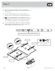
Step 3 å Separate the EXTENSION SLIDES (PP) from the EXTENSION RAILS (OO) as shown in the upper diagram below. Be prepared, the parts are greasy. å Fasten the EXTENSION RAILS (OO) to the RIGHT END (A) and UPRIGHT (E). Use four GOLD 5/16" FLAT HEAD SCREWS (QQQ). å NOTE: For each EXTENSION RAIL, turn a SCREW into the hole shown in the enlarged diagram. Then, slide the inner cartridge of the EXTENSION RAIL out to find the other hole that lines up with the hole in the ENDS and UPRIGHTS.
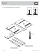
Step 4 å Carefully turn the UPRIGHT (E) over onto the TWIST-LOCK® surface. å Fasten the EXTENSION BLOCK (AA) to the UPRIGHT (E). Use two BLACK 1-1/4" FLAT HEAD SCREWS (HHH). å Fasten the BLACK CABINET RAILS (KK and LL) to the LEFT END (B) and EXTENSION BLOCK (AA). Use four GOLD 5/16" FLAT HEAD SCREWS (QQQ). å HHH NOTE: The CABINET RAILS are marked "CABINET RIGHT" and "CABINET LEFT" for easy identification.
Step 5 å Turn seventeen CAM SCREWS (8F) into the RIGHT END (A), UPRIGHT (E), HUTCH ENDS (C and D), and LEGS (I). A E C 8F (17 used) D I I I These holes must be here. This hole must be here. Page 10 409043 www.sauder.
Step 6 å Fasten the LEGS (I) to the ENDS (A and B) and UPRIGHT (E). Tighten nine HIDDEN CAMS. å Fasten a FOOT (FF) to each LEG (I). Use three BLACK 1-5/8" PAN HEAD SCREWS (FFF). Su TW rfa FA IS ce w ST T-L ith EN OC ER K® S These edges should be even. I These edges should be even. B FF I Su TW rfa FA IS ce w ST T-L ith EN OC ER K® S A These edges should be even. E FF Su TW rfa FA IS ce w ST T-L ith EN OC ER K® S This hole must be here.
Step 7 å Fasten the HUTCH UPRIGHT (F) and HUTCH BACK (N) to the TOP (G). Use six BLACK 1-7/8" FLAT HEAD SCREWS (EEE). å Fasten the DIVIDERS (L) to the TOP (G). Use four BROWN 1-1/2" FLAT HEAD SCREWS (GGG). Sur HIDface w DEN itho CA ut MS EEE Curved edge N BLACK 1-7/8" FLAT HEAD SCREW (6 used in this step) F G ed h is n Fi Rounded edge e ac rf su L Finished edge L G GGG BROWN 1-1/2" FLAT HEAD SCREW (4 used in this step) Page 12 409043 www.sauder.
Step 8 å Insert eight METAL PINS (VV) into the short edges of the HUTCH SHELVES (J and K). å Push the PINS (VV) into the holes of the HUTCH UPRIGHT (F). VV VV K ed h is n Fi e ac rf su Finished edge F J ed h is e n ac Fi urf s Finished edge VV www.sauder.
Step 9 å Fasten the HUTCH ENDS (C and D) to the HUTCH SHELVES (J and K) and HUTCH BACK (N). Tighten four HIDDEN CAMS. å NOTE: Be sure the METAL PINS in the HUTCH SHELVES insert into the holes in the ENDS. å Fasten the HUTCH ENDS (C and D) to the TOP (G). Use two BLACK 1-7/8" FLAT HEAD SCREWS (EEE). Curved edge D K N Curved edge G J C EEE BLACK 1-7/8" FLAT HEAD SCREW (2 used in this step) Page 14 409043 www.sauder.
Step 10 å Fasten the RIGHT END (A) to the TOP (G). Tighten two TWIST-LOCK® FASTENERS. å Insert a METAL PIN (VV) into each short edge of the BRACES (P). å Fasten the BRACES (P) to the RIGHT END (A). Tighten two HIDDEN CAMS. å NOTE: Be sure the METAL PINS in the BRACES insert into the holes in the RIGHT END. How to use the SAUDER TWIST-LOCK® FASTENER 1. Insert the dowel end of the FASTENER into the hole of the adjoining part.
Step 11 å Fasten the UPRIGHT (E) to the TOP (G). Tighten two TWIST-LOCK® FASTENERS. å Fasten the UPRIGHT (E) to the BRACES (P). Tighten two HIDDEN CAMS. å NOTE: Be sure the METAL PINS in the BRACES insert into the holes in the UPRIGHT. å Turn a CORD CLIP (AAA) into the TOP (G). Caution Do not stand the unit upright without the BACK fastened. The unit may collapse. P G E P AAA Page 16 409043 www.sauder.
Step 12 å Fasten two ANGLE BRACKETS (UU) to the BRACE (P). Use two BLACK 9/16" LARGE HEAD SCREWS (OOO). å NOTE: Be sure the edges of the ANGLE BRACKETS are even with the edge of the BRACE. å Fasten the BOTTOM MOLDING (CC) to the ANGLE BRACKETS (UU). Use two BLACK 9/16" LARGE HEAD SCREWS (OOO). å JJJ SILVER 1-1/8" FLAT HEAD SCREW (2 used for the TOP MOLDING) Fasten the TOP MOLDING (DD) to the TOP (G). Use two SILVER 1-1/8" FLAT HEAD SCREWS (JJJ).
Step 13 å Fasten the MODESTY PANEL (H) to the LEFT END (B). Tighten three TWIST-LOCK® FASTENERS. å Insert a METAL PIN (VV) into the edge of the LEFT END (B). H Sur f TW ace wi IS th FAS T-LO TEN CK® ERS B VV Page 18 409043 www.sauder.
Step 14 å å Carefully turn your unit over onto its front edges. å NOTE: Be sure the METAL PIN in the LEFT END inserts into the hole in the TOP. å Fasten the MODESTY PANEL (H) to the UPRIGHT (E) Use two BLACK 1-7/8" FLAT HEAD SCREWS (EEE). Fasten the MODESTY PANEL (H) and LEFT END (B) to the TOP (G). Tighten four TWIST-LOCK® FASTENERS. EEE BLACK 1-7/8" FLAT HEAD SCREW (2 used in this step) H B G E www.sauder.
Step 15 å Make equal margins along the long edges of the BACK (M). Be sure the back is against the bottom surface of the TOP (G). Push on opposite corners of your unit if needed to make it "square". å Fasten the BACK (M) to your unit using the NAILS (RRR). Caution Do not stand the unit upright without the BACK fastened. The unit may collapse. RRR NAIL (14 used in this step) Edge with no holes M G Page 20 409043 www.sauder.
Step 16 å Fasten the DRAWER FRONT BRACKETS (ZZ) to the HUTCH DRAWER SIDES (Y). Use four BLACK 1/2" FLAT HEAD SCREWS (PPP). å Fasten the DRAWER FRONT BRACKETS (ZZ) to the HUTCH DRAWER FRONT (X). Use two BLACK 9/16" LARGE HEAD SCREWS (OOO). Finished edge These holes must be here. Finished edge ZZ X Y ZZ Finished edge OOO Y BLACK 9/16" LARGE HEAD SCREW (2 used in this step) PPP BLACK 1/2" FLAT HEAD SCREW (4 used in this step) www.sauder.
Step 17 å Fasten the HUTCH DRAWER BACK (Z) to the HUTCH DRAWER SIDES (Y). Use two BLACK 1-1/4" FLAT HEAD SCREWS (HHH). å Push the METAL BRACKETS (WW) into the holes of the HUTCH DRAWER FRONT (X). å Fasten the KNOB (XX) to the HUTCH DRAWER FRONT (X). Use a SILVER 3/4" MACHINE SCREW (NNN). å Turn a CORD CLIP (AAA) into the HUTCH DRAWER BACK (Z).
Step 18 å å Turn the HUTCH DRAWER BOX over onto its top. å Make equal margins along two short edges of the HUTCH DRAWER BOTTOM (EE). Be sure the HUTCH DRAWER BOTTOM is against the METAL BRACKETS. Push on opposite corners of your box if needed to make it "square". å With a hammer, fasten the HUTCH DRAWER BOTTOM (EE) to the HUTCH DRAWER SIDES (Y) and HUTCH DRAWER BACK (Z) by tapping in the TACK GLIDES (YY) through the holes shown.
Step 19 å First, lay the LAPTOP PAD (DDD) so the velcro attached to the pad is facing up. å å Next, peel off the paper from the adhesive side. å Fasten the BLACK DRAWER SLIDES (MM and NN) to the SHELF MOLDINGS (BB). Use four BROWN 1" FLAT HEAD SCREWS (LLL). Finally, flip the pad over and press it firmly onto the center of the LAPTOP SHELF (Q). å NOTE: The DRAWER SLIDES are marked "DRAWER RIGHT" and "DRAWER LEFT" for easy identification.
Step 20 å Fasten the LARGE DRAWER SIDES (D253) to one of the LARGE DRAWER BOX FRONTS (D241). Use four BLACK 1-1/4" FLAT HEAD SCREWS (HHH). å Slide a DRAWER BOTTOM (D717) into the grooves in the LARGE DRAWER SIDES (D253). å Fasten the remaining LARGE DRAWER BOX FRONT (D241) to the LARGE DRAWER SIDES (D253). Use four BLACK 1-1/4" FLAT HEAD SCREWS (HHH). å Repeat this step for the other drawer. Be sure the grooves in each part line up with each other on the inside of the drawer.
Step 21 å Fasten the DRAWER RIGHT (40CC) and DRAWER LEFT (40CD) to the SMALL DRAWER SIDES (D270). Use four GOLD 5/16" FLAT HEAD SCREWS (QQQ). å Fasten the SMALL DRAWER FRONT (S) to a SMALL DRAWER BOX FRONT (D242). Use two BLACK 7/8" LARGE HEAD SCREWS (MMM). å Fasten the KNOB (XX) to the SMALL DRAWER FRONT (S). Use a BLACK 1-1/8" MACHINE SCREW (III).
Step 22 å Fasten the EXTENSION SLIDES (PP) to the DRAWER SIDES (D253). Use four GOLD 5/16" FLAT HEAD SCREWS (QQQ) through holes #1 and #3. å Fasten the LARGE DRAWER FRONT (O) to a LARGE DRAWER BOX FRONT (D241). Use four BLACK 7/8" LARGE HEAD SCREWS (MMM). å Fasten a KNOB (XX) to the LARGE DRAWER FRONT (O). Use a BLACK 1-1/8" MACHINE SCREW (III). å Push the FILE GLIDES (QQ) centering them onto the LARGE DRAWER SIDES (D253).
Step 23 å å Carefully stand your unit upright. å To insert the small drawer into your unit, tip the front of the drawer down and drop the rollers on the drawer behind the rollers on the unit. Lift the front of the drawer up and slide it into the unit. Repeat this step to insert the LAPTOP SHELF (Q). å NOTE: The DRAWER FRONTS may need adjustments. To adjust the DRAWER FRONTS, loosen the SCREWS in the DRAWER FRONTS. Make adjustments and tighten the SCREWS.
409043 Utilisez les instructions d’assemblage en français avec les schémas étape par étape du manuel d’instruction en anglais. Chaque étape en français correspond à la même étape en anglais. La pièce devant être attachée à l’élément est représentée en gris sur les schémas de chaque étape pour plus de précision. Comparer la “Liste de pièces” ci-dessous avec la “PART IDENTIFICATION” du manuel en anglais pour vous familiariser avec les pièces avant l’assemblage.
ÉTAPE 1 ÉTAPE 5 REMARQUE : Ne pas serrer les FIXATIONS TWIST-LOCK® à ce stade de l’assemblage. Faire tourner dix-sept VIS D’EXCENTRIQUE (8F) dans l’EXTRÉMITÉ DROITE (A), le MONTANT (E), les EXTRÉMITÉS DE SURMEUBLE (C et D) et les PIEDS (I). Assembler l’élément sur un sol à moquette ou sur le carton vide pour éviter d’endommager l’élément ou le sol. ÉTAPE 6 Pour commencer l’assemblage, enfoncer une FIXATION TWIST-LOCK® SAUDER (RR) dans les gros trous de l’EXTRÉMITÉ DROITE (A) et l’EXTRÉMITÉ GAUCHE (B).
ÉTAPE 10 ÉTAPE 13 Utilisation de la FIXATION TWIST-LOCK® SAUDER (Consulter le schéma agrandi.) Fixer le VOILE DE FOND (H) à l’EXTRÉMITÉ GAUCHE (B). Serrer trois FIXATIONS TWIST-LOCK®. 1. Insérer l’extrémité filetée de la FIXATION dans le trou de la pièce attenante. Insérer une GOUPILLE EN MÉTAL (VV) dans le chant de l’EXTRÉMITÉ GAUCHE (B). REMARQUE : L’extrémité filetée de la FIXATION doit rester complètement insérée dans le trou de la pièce attenante lorsque l’on bloque la FIXATION. ÉTAPE 14 2.
ÉTAPE 18 ÉTAPE 21 Retourner le CAISSON DE TIROIR DE SURMEUBLE sur son dessus. Fixer le TIROIR DROIT (40CC) et le TIROIR GAUCHE (40CD) aux CÔTÉS DE PETIT TIROIR (D270). Utiliser quatre VIS DORÉES TÊTE PLATE 8 mm (PP). Faire glisser le FOND DE TIROIR DE SURMEUBLE (EE) sous les CONSOLES EN MÉTAL (WW). Effectuer des marges égales le long des deux chants courts du FOND DE TIROIR DE SURMEUBLE (EE). S’assurer que le FOND DE TIROIR DE SURMEUBLE se trouve contre les CONSOLES EN MÉTAL.
409043 Use estas instrucciones de ensamblaje en español junto con las figuras paso-a-paso provistas en el folleto inglés. Cada paso en español corresponde al mismo paso en inglés. Se destacan las figuras de cada paso con una tonalidad oscura para mostrar precisamente cual parte se debe montar a la unidad. Compare la “Lista de Part” abajo con la “Part Identification” en el folleto en inglés para familiarizarse con Las partes de ensamblaje.
PASO 1 PASO 6 NOTA: No apriete los SUJETADORES TWIST-LOCK® por ahora. Fije las PATAS (I) a los EXTREMOS (A y B) y al PARAL (E). Apriete nueve EXCÉNTRICOS ESCONDIDOS. Ensamble la unidad sobre un piso alfombrado o sobre el cartón vacío para evitar rayar la unidad o el piso. Para comenzar el ensamblaje, empuje un SUJETADOR TWIST-LOCK® SAUDER (RR) dentro de los agujeros grandes del EXTREMO DERECHO (A) y del EXTREMO IZQUIERDO (B). Repita este paso para el PARAL (E) y el VELO DE FONDO (H).
PASO 10 (CONTINUACIÓN) PASO 15 Fije las RIOSTRAS (P) al EXTREMO DERECHO (A). Apriete dos EXCÉNTRICOS ESCONDIDOS. Precaución: No coloque la unidad en posición vertical hasta que se fije el DORSO. La unidad podría caerse. NOTA: Asegúrese de insertar las ESPIGAS DE METAL de las RIOSTRAS dentro de los agujeros del EXTREMO DERECHO. Verifique que los márgenes son iguales a lo largo de los bordes largos del DORSO (M). Asegúrese que el dorso esté contra la superficie de fondo del PANEL SUPERIOR (G).
PASO 19 PASO 22 Primero, coloque la ALMOHADILLA DE COMPUTAORA PORTÁTIL (DDD) de manera que el Velcro fijado a la almohadilla quede mirando hacia arriba. Fije las CORREDERAS DE EXTENSIÓN (PP) a los LADOS DE CAJÓN (D253). Utilice cuatro tornillos DORADOS de cabeza PERDIDA de 8 mm (QQQ) a través de los agujeros No. 1 y No. 3. Luego, desprenda el papel del lado adhesivo. Fije la CARA DE CAJÓN GRANDE (O) al FRENTE DE CAJÓN GRANDE (D241). Utilice cuatro TORNILLOS NEGROS DE CABEZA GRANDE de 22 mm (MMM).
WARNING Please use your furniture correctly and safely. Improper use can cause safety hazards, or damage to your furniture or household items. Carefully read the following chart. Look out for: What can happen: How to avoid the problem: • Overloaded shelves and drawers. • Improper loading can cause the product to be top-heavy. • Risk of injury. • Top-heavy furniture can tip over. • Overloaded shelves and drawers can break. • Never exceed the weight limits shown in the instructions.
ADVERTENCIA Por favor use el mobiliario correcta y seguramente. El mal uso puede causar riesgos de seguridad o daño a las unidades o artículos domésticos. Cuidadosamente lea la tabla a continuación. Esté alerto de: Puede ocurrir: Evitar el problema: • Estantes y cajones sobrecargados • Riesgo de lesiones. • Cargar el producto de manera inadecuada • El mobiliario inestable puede volcarse. puede causar la inestabilidad. • Estantes y cajones sobrecargados pueden romperse.
5-YEAR LIMITED WARRANTY 1. Sauder Woodworking Co. (Sauder®) provides limited warranty coverage to the original purchaser of this product for a period of five years from the date of purchase against defects in materials or workmanship of Sauder furniture components. As used in this Warranty, “defect” means imperfections in components which substantially impair the utility of the product. This Warranty gives you specific legal rights, and you may also have other rights which vary from state to state. 2.
Dear Valued Customer: So, how did it go? Thanks so much for choosing Sauder® furniture. I hope the purchase and assembly process was a positive experience and you feel good about the furniture you just built. If you need assistance or want to learn more, please contact our award-winning, Ohio-based customer service team at 800-523-3987 or Sauder.com. Set a world record for speed? Feeling good about yourself? Nice. Get social with it on any of these quality share sites.