sauder.com For all your newfangled gadgetry. Computer Desk Shoal Creek Collection | 409936 NOTE: THIS INSTRUCTION BOOKLET CONTAINS IMPORTANT SAFETY INFORMATION. Need help? Visit Sauder.com to view video assembly tips or chat with a live rep. Prefer the phone? Call 1-800-523-3987. Share your journey! PLEASE READ AND KEEP FOR FUTURE REFERENCE. English pg 1-22 Français pg 23-25 Español pg 26-28 Lot # 368943 02/09/15 Purchased: __________________ Be sure to give us a ring before making any returns.
Table of Contents Part Identification Hardware Identification Assembly Steps Assembly Tools Required 2-3 No. 2 Phillips Screwdriver Tip Shown Actual Size 4-5 6-22 Hammer Français 23-25 Español 26-28 Safety 29-30 Warranty Not actual size Skip the power trip. This time. 31 Part Identification å While not all parts are labeled, some of the parts will have a label or an inked letter on the edge to help distinguish similar parts from each other.
Now you know our ABCs. Part Identification D J A E C P F H G J D74 B D20 D716 I D21 P www.sauder.
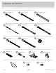
Hardware Identification å Screws are shown actual size. You may receive extra hardware with your unit. Q RIGHT CABINET RAIL - 1 T R 40CA CABINET RIGHT - 1 LEFT DRAWER SLIDE - 1 40CC DRAWER RIGHT - 1 2F CAM DOWEL - 6 EE Page 4 CAM SCREW - 10 FF RIGHT DRAWER SLIDE - 1 40CB CABINET LEFT - 1 1F 40CD DRAWER LEFT - 1 8F PULL - 2 S LEFT CABINET RAIL - 1 BB HINGE - 2 SLIDE CAM - 2 409936 HIDDEN CAM - 16 CC ANGLE BRACKET - 3 GG CAM COVER - 7 www.sauder.
Hardware Identification å Screws are shown actual size. You may receive extra hardware with your unit. HH BLACK 2-1/4" FLAT HEAD SCREW - 6 II JJ GOLD 1" MACHINE SCREW - 4 KK LL BLACK 9/16" LARGE HEAD SCREW - 6 MM BLACK 9/16" FLAT HEAD SCREW - 4 NN SILVER 9/16" LARGE HEAD SCREW - 2 OO GOLD 5/16" FLAT HEAD SCREW - 12 BROWN 1" FLAT HEAD SCREW - 4 SILVER 5/8" FLAT HEAD SCREW - 4 30S BLACK 1-9/16" FLAT HEAD SCREW - 4 www.sauder.
Look for this icon. It means a video assembly tip is available at www.sauder.com/services/tips Step 1 å Assemble your unit on a carpeted floor or on the empty carton to avoid scratching your unit or the floor. å Push sixteen HIDDEN CAMS (1F) into the ENDS (A and B), UPRIGHT (C), and MODESTY PANEL (E). Then, insert the metal end of six CAM DOWELS (2F) into the HIDDEN CAMS. Do not tighten the HIDDEN CAMS in this step. Arrow Do not insert CAM DOWELS into this part.
Step 2 å å Turn ten CAM SCREWS (8F) into the LEGS (H, I, and J). Remember: Righty tighty. Lefty loosey. Fasten the FRONT LEGS (H and I) to the ENDS (A and B). Tighten six HIDDEN CAMS. 8F (10 used) J H J I These surfaces should be even. S HI urfa DD ce EN wi CA th M S Edge with CAM DOWELS These surfaces should be even. H S HI urfa DD ce EN wi CA th M S A Curved edge B I Curved edge 1 2 www.sauder.
Step 3 å Turn four BLACK 9/16" FLAT HEAD SCREWS (MM) into the other surfaces of the ENDS (A and B) until the shoulders of the SCREWS rest on the surfaces of the ENDS. å Slide the SIDE MOLDINGS (P) onto the ENDS (A and B). Line up the grooves in the MOLDINGS over the heads of the SCREWS in the ENDS. Apply pressure with your hands as you guide the MOLDINGS over the SCREWS and onto the ENDS. P A B P Shoulder MM BLACK 9/16" FLAT HEAD SCREW (4 used in this step) Page 8 409936 www.sauder.
Step 4 å Turn the ENDS (A and B) over and fasten the REAR LEGS (J) to the ENDS. Use six BLACK 2-1/4" FLAT HEAD SCREWS (HH). HH S HI urfa DD ce EN wi CA th M S BLACK 2-1/4" FLAT HEAD SCREW (6 used in this step) A S HI urfa DD ce EN wi CA th M S J J B Curved edge www.sauder.
Step 5 å Fasten the CABINET RIGHT (40CA) and CABINET LEFT (40CB) to the RIGHT END (A) and UPRIGHT (C). Use four GOLD 5/16" FLAT HEAD SCREWS (OO) through holes #1 and #3. OO Roller end GOLD 5/16" FLAT HEAD SCREW (4 used in this step) 1 2 3 4 3 Roller end S HI urfa DD ce EN wi CA th M S 4 H A 2 C S H urf ID ac D e E w N it C ho A u M t S 1 Finished edge Page 10 409936 www.sauder.
Step 6 å Fasten the CABINET RAILS (Q and R) to the LEFT END (B) and to the other surface of the UPRIGHT (C). Use four GOLD 5/16" FLAT HEAD SCREWS (OO). å NOTE: The CABINET RAILS are marked "CABINET RIGHT" and "CABINET LEFT" for easy identification. Roller end OO GOLD 5/16" FLAT HEAD SCREW (4 used in this step) Q ith MS e w CA c rfa EN Su IDD H Finished edge C Roller end S HI urfa DD ce EN wi CA th M S R B I www.sauder.
Step 7 å Fasten the MODESTY PANEL (E) to the ENDS (A and B). Tighten four HIDDEN CAMS. H A S H urf ID a D ce E w N i C th A M S These holes must be here. I E B Page 12 409936 www.sauder.
Step 8 å Fasten three ANGLE BRACKETS (CC) to the MODESTY PANEL (E). Use three BLACK 9/16" LARGE HEAD SCREWS (LL). å NOTE: Be sure the edges of the ANGLE BRACKETS are even with the edge of the MODESTY PANEL. LL BLACK 9/16" LARGE HEAD SCREW (3 used in this step) CC A E B www.sauder.
Step 9 å Fasten the ENDS (A and B) to the TOP (D). Tighten four HIDDEN CAMS. å Then, fasten the MODESTY PANEL (E) to the TOP (D). Use three BLACK 9/16" LARGE HEAD SCREWS (LL). LL BLACK 9/16" LARGE HEAD SCREW (3 used in this step) Long finished edge fi Un ce rfa u ds D he s i n A E B Caution Risk of damage or injury. HIDDEN CAMS must be completely tightened. HIDDEN CAMS that are not completely tightened may loosen, and parts may separate.
Step 10 å Fasten the UPRIGHT (C) to the TOP (D). Tighten two HIDDEN CAMS. Almost time to celebrate! With a nap. Finished edge D C Surface with HIDDEN CAMS Maximum 210 degrees Arrow Minimum 190 degrees www.sauder.
Step 11 å Fasten the HINGES (BB) to the KEYBOARD FRONT (G). Use four SILVER 5/8" FLAT HEAD SCREWS (KK) å Fasten the KEYBOARD HINGES (BB) to the KEYBOARD SHELF (F). Use two SILVER 9/16" LARGE HEAD SCREWS (NN). NN KK SILVER 5/8" FLAT HEAD SCREW (4 used for KEYBOARD FRONT) SILVER 9/16" LARGE HEAD SCREW (2 used for KEYBOARD SHELF) BB ed h is n Fi F e ac rf su G Page 16 409936 www.sauder.
Step 12 å Fasten the DRAWER SLIDES (S and T) to the KEYBOARD SHELF (F). Use four BROWN 1" FLAT HEAD SCREWS (II). å NOTE: The DRAWER SLIDES are marked "DRAWER RIGHT" and "DRAWER LEFT" for easy identification. å Fasten a PULL (EE) to the KEYBOARD FRONT (G). Use two GOLD 1" MACHINE SCREWS (JJ). Roller end JJ T GOLD 1" MACHINE SCREW (2 used for the PULL) Roller end F EE G S II BROWN 1" FLAT HEAD SCREW (4 used for the SLIDES) www.sauder.
Step 13 VIEW THE T-LOCK BOX VIDEO 1 2 The tabs should insert freely into the slots. Gently tilt the DRAWER SIDES side to side until the tabs slip into the slots. With the palm of your hand, tap the DRAWER BOTTOM down into the groove. Un fi su nish rfa ed ce D716 D20 D20 D21 D21 K K Be sure the DRAWER BOTTOM inserts into the DRAWER FRONT groove. Groove å Insert the DRAWER SIDES (D20 and D21) at an angle into the slot at each end of the DRAWER FRONT (K).
Step 14 å å Insert a SLIDE CAM (FF) into the DRAWER SIDES (D20 and D21). å NOTE: The screw head in the CAM must be visible through the slotted hole in the SLIDE. Fasten the DRAWER RIGHT (40CC) and DRAWER LEFT (40CD) to the DRAWER SIDES (D20 and D21). Use four GOLD 5/16" FLAT HEAD SCREWS (OO) through holes #2 and #4. Roller end Screw head - turn the CAM to line up holes in SLIDES with holes in DRAWER SIDES.
Step 15 å Fasten a PULL (EE) to the DRAWER FRONT (K). Use two GOLD 1" MACHINE SCREWS (JJ). JJ GOLD 1" MACHINE SCREW (2 used for the PULL) EE Page 20 K 409936 www.sauder.
Step 16 å å Carefully stand your unit upright. å å Repeat this step to insert the KEYBOARD SHELF (F). Pro Tip: Lift with your legs. And, you know, your arms. To insert the drawer into your unit, tip the front of the drawer down and drop the rollers on the drawer behind the rollers on the unit. Lift the front of the drawer up and slide it into the unit. Push a CAM COVER (GG) onto each visible HIDDEN CAM. 50 lbs. 10 lbs. F 15 lbs. GG (7 used) To cover HIDDEN CAMS www.sauder.
Step 17 å To make adjustments to the drawer, loosen SCREW #4 in the SLIDES a 1/4 turn, then turn the CAM clockwise or counter-clockwise. Notice how the drawer raises or lowers as you turn the CAM. The higher the screw in the oblong hole, the higher your drawer front will be. The lower the screw, the lower the drawer front. By adjusting the drawer this way, it will help the DRAWER FRONT line up better when closed. Tighten the SCREW when finished with adjustments.
409936 Utilisez les instructions d’assemblage en français avec les schémas étape par étape du manuel d’instruction en anglais. Chaque étape en français correspond à la même étape en anglais. La pièce devant être attachée à l’élément est représentée en gris sur les schémas de chaque étape pour plus de précision. Comparer la “Liste de pièces” ci-dessous avec la “PART IDENTIFICATION” du manuel en anglais pour vous familiariser avec les pièces avant l’assemblage.
ÉTAPE 1 ÉTAPE 6 Ne pas serrer les EXCENTRIQUES ESCAMOTABLES dans cette étape. Fixer les GLISSIÈRES D'ÉLÉMENT (Q et R) à l'EXTRÉMITÉ GAUCHE (B) et sur l'autre surface du MONTANT (C). Utiliser quatre VIS TÊTE PLATE 8 mm DORÉES (OO). Assembler l'élément sur un sol à moquette ou sur le carton vide pour éviter d'endommager l'élément ou le sol. Enfoncer seize EXCENTRIQUES ESCAMOTABLES (1F) dans les EXTRÉMITÉS (A et B), le MONTANT (C) et le VOILE DE FOND (E).
ÉTAPE 11 ÉTAPE 15 Fixer les CHARNIÈRES (BB) au DEVANT DE TABLETTE DE CLAVIER (G). Utiliser quatre VIS TÊTE PLATE 16 mm ARGENTÉES (KK). Fixer une POIGNÉE (EE) sur le DEVANT DE TIROIR (K). Utiliser deux VIS À MÉTAUX 25 mm DORÉES (JJ). Fixer les CHARNIÈRES DE TABLETTE DE CLAVIER (BB) à la TABLETTE DE CLAVIER (F). Utiliser deux VIS TÊTE LARGE 14 mm ARGENTÉES (NN). ÉTAPE 16 ÉTAPE 12 Fixer les COULISSES DE TIROIR (S et T) à la TABLETTE DE CLAVIER (F). Utiliser quatre VIS TÊTE PLATE 25 mm MARRON (II).
409936 Use estas instrucciones de ensamblaje en español junto con las figuras paso-a-paso provistas en el folleto inglés. Cada paso en español corresponde al mismo paso en inglés. Se destacan las figuras de cada paso con una tonalidad oscura para mostrar precisamente cual parte se debe montar a la unidad. Compare la “Lista de Part” abajo con la “Part Identification” en el folleto en inglés para familiarizarse con Las partes de ensamblaje.
PASO 1 PASO 6 No apriete los EXCÉNTRICOS ESCONDIDOS en este paso. Fije los RIELES DE GABINETE (Q y R) al EXTREMO IZQUIERDO (B) y a la otra superficie del PARAL (C). Utilice cuatro TORNILLOS DORADOS DE CABEZA PERDIDA de 8 mm (OO). Ensamble la unidad sobre un piso alfombrado o sobre el cartón vacío para evitar rayar la unidad o el piso. Empuje dieciséis EXCÉNTRICOS ESCONDIDOS (1F) dentro de los EXTREMOS (A y B), el PARAL (C) y el VELO DE FONDO (E).
PASO 11 PASO 15 Fije las BISAGRAS (BB) a la CARA DE ESTANTE DE TECLADO (G). Utilice cuatro TORNILLOS PLATEADOS DE CABEZA PERDIDA de 16 mm (KK). Fije un TIRADOR (EE) a la CARA DE CAJÓN (K). Utilice dos TORNILLOS DORADOS PARA METAL de 25 mm (JJ). Fije las BISAGRAS DE ESTANTE DE TECLADO (BB) al ESTANTE DE TECLADO (F). Utilice dos TORNILLOS PLATEADOS DE CABEZA GRANDE de 14 mm (NN). PASO 16 Cuidadosamente ponga la unidad en posición vertical.
WARNING Please use your furniture correctly and safely. Improper use can cause safety hazards, or damage to your furniture or household items. Carefully read the following chart. Look out for: What can happen: How to avoid the problem: • Overloaded shelves and drawers. • Improper loading can cause the product to be top-heavy. • Risk of injury. • Top-heavy furniture can tip over. • Overloaded shelves and drawers can break. • Never exceed the weight limits shown in the instructions.
ADVERTENCIA Por favor use el mobiliario correcta y seguramente. El mal uso puede causar riesgos de seguridad o daño a las unidades o artículos domésticos. Cuidadosamente lea la tabla a continuación. Esté alerto de: Puede ocurrir: Evitar el problema: • Estantes y cajones sobrecargados • Riesgo de lesiones. • Cargar el producto de manera inadecuada • El mobiliario inestable puede volcarse. puede causar la inestabilidad. • Estantes y cajones sobrecargados pueden romperse.
5-YEAR LIMITED WARRANTY 1. Sauder Woodworking Co. (Sauder®) provides limited warranty coverage to the original purchaser of this product for a period of five years from the date of purchase against defects in materials or workmanship of Sauder furniture components. As used in this Warranty, “defect” means imperfections in components which substantially impair the utility of the product. This Warranty gives you specific legal rights, and you may also have other rights which vary from state to state. 2.
Dear Valued Customer: So, how did it go? Thanks so much for choosing Sauder® furniture. I hope the purchase and assembly process was a positive experience and you feel good about the furniture you just built. If you need assistance or want to learn more, please contact our award-winning, Ohio-based customer service team at 800-523-3987 or Sauder.com. Set a world record for speed? Feeling good about yourself? Nice. Get social with it on any of these quality share sites.