
Instructions / Assembly


Step 14
411197 www.sauder.com/servicesPae 18
å
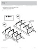
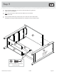
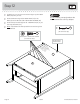
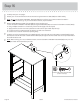
Insert a SLIDE CAM (DD) into the LARGE DRAWER SIDES (D132 and D138).
å
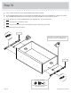
Fasten a DRAWER RIGHT (40DC) to the LARGE RIGHT DRAWER SIDE (D132) and a DRAWER LEFT (40DD) to the LARGE
LEFT DRAWER SIDE (D138). Use four GOLD 5/16" FLAT HEAD SCREWS (TT) throuh holes #1 and #2.
å
NOTE: The parts are marked "DRAWER RIGHT" and "DRAWER LEFT" for easy identifi cation.
å
NOTE: The lides are not intended to rotate.
å
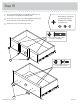
NOTE: The screw head in the CAM must be visible throuh the slotted hole in the SLIDE.
å
Repeat this step for the other drawers.
1
2
1
2
GOLD 5/16" FLAT HEAD SCREW
(16 used in this step)
TT
(4 screws per drawer)
Glide end
Glide end
D138
D132
Screw head - turn CAM to line up holes in
the SLIDES with holes in DRAWER SIDES
DD
DD