sauder.com WARNING CHOKING HAZARD - Small Parts Not for children under 3 years. Adult assembly required. 4-Drawer Chest Shoal Creek Collection | Model 411197 NOTE: THIS INSTRUCTION BOOKLET CONTAINS IMPORTANT SAFETY INFORMATION. Need help? Visit Sauder.com to view video assembly tips or chat with a live rep. Prefer the phone? Call 1-800-523-3987. Share your journey! PLEASE READ AND KEEP FOR FUTURE REFERENCE.
Table of Contents Part Identification 2-3 Hardware Identification Assembly Steps Assembly Tools Required No. 2 Phillips Screwdriver Tip Shown Actual Size 4 5-22 Hammer Français 23-25 Español 26-28 Safety 29-30 Warranty Not actual size Skip the power trip. This time. 31 Now you know our ABCs. Part Identification å While not all parts are labeled, some of the parts will have a label or an inked letter on the edge to help distinguish similar parts from each other.
Part Identification C2 I VV A2 G M73 E I D B2 D H D10 D174 D983 M73 D11 M65 J2 D132 D175 D983 D138 www.sauder.
Hardware Identification å Screws are shown actual size. You may receive extra hardware with your unit. 40DA 12F UNIVERSAL CABINET RAIL - 8 40DC TWIST-LOCK® FASTENER - 8 2G DRAWER RIGHT - 4 40DD DRAWER LEFT - 4 10A SLIDE CAM - 8 1F HIDDEN CAM - 10 8F CAM SCREW - 10 METAL BRACKET - 4 11L WARNING LABEL - 1 31K PULL - 6 32K KNOB - 3 10/16 WARNING AVERTISSEMENT ADVERTENCIA Serious or fatal crushing injuries can occur from furniture tipover.
Look for this icon. It means a video assembly tip is available at www.sauder.com/services/tips Step 1 å Assemble your unit on a carpeted floor or on the empty carton to avoid scratching your unit or the floor. å To begin assembly, push a SAUDER TWIST-LOCK® FASTENER (12F) into the large holes in the ENDS (A2 and B2). Repeat this step for the BOTTOMS (D). Scan this QR code or go to this address: http://qr.sauder.com/?ID=1714 to watch a video on how to assemble your unit.
Step 2 å Push ten HIDDEN CAMS (1F) into the ENDS (A2 and B2) and DRAWER BRACES (M65). Arrow 1F A2 B2 M65 M65 Arrow (10 used) 1F M65 M65 Arrow Arrow 1F Hole The arrow in the HIDDEN CAM must point toward the hole in the edge of the board. Page 6 411197 www.sauder.
Step 3 å Turn ten CAM SCREWS (8F) into the FRONT LEGS (G and H) and DRAWER FRONTS (J2 and O2). (10 used) 8F H G O2 O2 O2 J2 www.sauder.
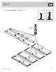
Step 4 å Fasten the REAR LEGS (I) to the ENDS (A2 and B2). Use six BLACK 2-1/4" FLAT HEAD SCREWS (26S). Remember: Righty tighty. Lefty loosey. 26S BLACK 2-1/4" FLAT HEAD SCREW (6 used in this step) Edge with TWIST-LOCK® FASTENERS S TW urfa FA IS ce ST T- wi EN LO tho ER CK ut S ® B2 Edge with TWIST-LOCK® FASTENERS I I S TW urfa FA IS ce ST T- wi EN LO tho ER CK ut S ® A2 Angled edge Page 8 411197 www.sauder.
Step 5 å Turn four BLACK 9/16" FLAT HEAD SCREWS (32S) into the ENDS (A2 and B2) until the shoulders of the SCREWS rest on the surfaces of the ENDS. å Slide the END MOLDINGS (M73) onto the ENDS (A2 and B2). Line up the grooves in the MOLDINGS over the heads of the SCREWS in the ENDS. These edges should be even. B2 M73 A2 Shoulder M73 These edges should be even. 32S Apply pressure with your hands as you guide the MOLDINGS over the SCREWS and onto the ENDS.
Step 6 å å NOTE: Carefully turn your ENDS (A2 and B2) over. Fasten the FRONT LEGS (G and H) to the ENDS (A2 and B2). Tighten six HIDDEN CAMS. 1 2 These surfaces should be even. G These surfaces should be even. Angled edge Su TW rfa FA IS ce ST T- wit EN LO h ER CK S ® A2 Su TW rfa FA IS ce ST T- wit EN LO h ER CK S ® B2 H Angled edge Page 10 411197 www.sauder.
Step 7 VIEW THE DRAWER GLIDE VIDEO å Fasten the UNIVERSAL CABINET RAILS* (40DA) to the ENDS (A2 and B2). Use sixteen GOLD 5/16" FLAT HEAD SCREWS (3S) through holes #1 and #4. å *patent pending glide system 3S GOLD 5/16" FLAT HEAD SCREW (16 used in this step) 1 Glide end 2 1 3 4 2 1 3 4 3 2 1 3 4 4 2 A2 3 4 3 4 2 3 1 G Su TW rfa FA IS ce ST T- wit EN LO h ER CK S ® 2 1 4 2 3 1 4 2 B2 Su TW rfa FA IS ce ST T- wit EN LO h ER CK S ® 1 Glide end www.sauder.
Step 8 å Fasten the LEFT END (B2) to the TOP (C2). Tighten two TWIST-LOCK® FASTENERS. Caution Do not stand the unit upright without the BACK fastened. The unit may collapse. How to use the SAUDER TWIST-LOCK® FASTENER 1. Insert the dowel end of the FASTENER into the hole of the adjoining part. NOTE: The dowel end of the FASTENER must remain fully inserted in the hole of the adjoining part while locking the FASTENER. 2. Tighten the FASTENER with a Phillips screwdriver as tight as possible.
Step 9 å å å Fasten four METAL BRACKETS (2G) to the BACK (E). Use four BLACK 9/16" LARGE HEAD SCREWS (1S). NOTE: Be sure the METAL BRACKETS are even with the edges of the BACK. Fasten the BACK (E) to the LEFT END (B2). Use two BLACK 9/16" LARGE HEAD SCREWS (1S) through the METAL BRACKETS on the BACK and into the LEFT END. 2G 1S E BLACK 9/16" LARGE HEAD SCREW (6 used in this step) 2G B2 The six holes on the other surface should be closer to this edge. TS th KE wi AC ce BR rfa L Su ETA M E www.
Step 10 å Insert a METAL PIN (1R) into the hole in each short edge of the BOTTOMS (D). å Fasten the BOTTOMS (D) to the LEFT END (B2). Tighten two TWIST-LOCK® FASTENERS. å NOTE: Be sure the METAL PINS in the BOTTOMS insert into the holes in the LEFT END. Don't worry. It isn't Rome. This can be built in a day. Finished edge B2 1R D D Su TWrface FA IST- with ST LO ou EN CK t ER ® S Su TWrface FA IST- with ST LO ou EN CK t ER ® S 1R Finished edge Page 14 411197 www.sauder.
Step 11 å Fasten the RIGHT END (A2) to the TOP (C2) and BOTTOMS (D). Tighten four TWIST-LOCK® FASTENERS. å NOTE: Be sure the METAL PINS in the BOTTOMS insert into the holes in the RIGHT END. å Fasten the RIGHT END (A2) to the BACK (E). Use two BLACK 9/16" LARGE HEAD SCREWS (1S) through the METAL BRACKETS on the BACK and into the RIGHT END. C2 D G E D A2 ut itho® w e fac CK SurIST-LORS TW TENE FAS 1S BLACK 9/16" LARGE HEAD SCREW (2 used in this step) www.sauder.
Step 12 å Carefully turn your unit over onto its front edges. Lay the LARGE BACK (VV) over your unit. å Fasten the bottom edge of the LARGE BACK (VV) to the BACK (E). Use six BLACK 9/16" LARGE HEAD SCREWS (1S). å Fasten the top and side edges of the LARGE BACK (VV) to your unit using the NAILS (1N). å NOTE: A perforation has been provided for access through the LARGE BACK. Caution Do not stand the unit upright without the BACK fastened. The unit may collapse.
Step 13 VIEW THE T-LOCK BOX VIDEO 1 2 The tabs should insert freely into the slots. Gently tilt the DRAWER SIDES side to side until the tabs slip into the slots. With the palm of your hand, tap the DRAWER BOTTOM down into the groove. Un fi su nish rfa ed ce D132 D983 D132 O2 D138 O2 Be sure the DRAWER BOTTOM inserts into the DRAWER FRONT groove. Groove å D138 Insert the LARGE DRAWER SIDES (D132 and D138) at an angle into the slot at each end of the LARGE DRAWER FRONT (O2).
Step 14 VIEW THE DRAWER GLIDE VIDEO å å Insert a SLIDE CAM (10A) into the LARGE DRAWER SIDES (D132 and D138). å å å NOTE: The screw head in the CAM must be visible through the slotted hole in the SLIDE. Fasten a DRAWER RIGHT (40DC) to the LARGE RIGHT DRAWER SIDE (D132) and a DRAWER LEFT (40DD) to the LARGE LEFT DRAWER SIDE (D138). Use four GOLD 5/16" FLAT HEAD SCREWS (3S) through holes #1 and #2. NOTE: The glides are not intended to rotate. Repeat this step for the other drawers.
Step 15 å Fasten three KNOBS (32K) to the DRAWER FRONT (J2). Use three BLACK 1-1/8" MACHINE SCREWS (21S). å Fasten two PULLS (31K) to the LARGE DRAWER FRONT (O2). Use four SILVER 3/4" MACHINE SCREWS (20S). å Repeat this step for the other large drawers. Want options? Customize your item with add-on hardware kits available on sauder.com. 21S BLACK 1-1/8" MACHINE SCREW (3 used for the KNOBS) J2 32K 20S SILVER 3/4" MACHINE SCREW (12 used for the PULLS) O2 31K www.sauder.
Step 16 å å å Carefully stand your unit upright. å INSTALLATION INSTRUCTIONS: (Also available at www.yl-anchors.com) 1. Insert the SAFETY DRYWALL ANCHOR (61M) through the WASHER (13M) and one end of the SAFETY STRAP (60M). 2. Using a Phillips screwdriver or a hand drill, press the screw slightly onto the drywall. 3. Apply pressure; turn the screw until a pilot hole is made and the nylon sheath slips through. 4. Turn the screw until it is flush against the wall and you feel a firm resistance. 5.
Step 17 å To insert the drawers into your unit, tip the front of the drawers down and drop the glides on the drawers behind the glides on the unit. Lift the front of the drawers up and slide them into the unit å Apply the WARNING LABEL (11L) to the upper DRAWER BOTTOM (D983). You should be able to read the label when the drawer is open. When the drawer is closed, it will hide the label. Peel off the backing and apply the label as shown in the diagram.
Step 18 å To make adjustments to the drawers, loosen SCREW #2 in the SLIDES a 1/4 turn, then turn the CAM clockwise or counter-clockwise. Notice how the drawer raises or lowers as you turn the CAM. The higher the screw in the oblong hole, the higher your drawer front will be. The lower the screw, the lower the drawer front. By adjusting the drawers this way, it will help the DRAWER FRONTS line up better when closed. Tighten the SCREW when finished with adjustments.
Modèle 411197 Utilisez les instructions d’assemblage en français avec les schémas étape par étape du manuel d’instruction en anglais. Chaque étape en français correspond à la même étape en anglais. La pièce devant être attachée à l’élément est représentée en gris sur les schémas de chaque étape pour plus de précision. Comparer la “Liste de pièces” ci-dessous avec la “PART IDENTIFICATION” du manuel en anglais pour vous familiariser avec les pièces avant l’assemblage.
ÉTAPE 1 ÉTAPE 8 Ne pas serrer les FIXATIONS TWIST-LOCK® à cette étape. Assembler l'élément sur un sol à moquette ou sur le carton vide pour éviter d'endommager l'élément ou le sol. Pour commencer l'assemblage, enfoncer une FIXATION TWIST-LOCK® SAUDER (12F) dans les gros trous des EXTRÉMITÉS (A2 et B2). Répéter cette étape pour les DESSOUS (D). Attention: Ne pas relever l'élément dans sa position verticale avant d'avoir fixé l’ARRIÈRE. L'élément risque de s'effondrer.
ÉTAPE 12 ÉTAPE 16 Attention: Ne pas relever l'élément dans sa position verticale avant d'avoir fixé l’ARRIÈRE. L'élément risque de s'effondrer. Relever, avec précaution, l'élément dans sa position verticale. Placer l'élément dans son emplacement final. Il est recommandé d’utiliser la SANGLE DE SÉCURITÉ (60M) pour stabilité additionnelle. REMARQUE : Ne pas tourner le DISPOSITIF DE SÉCURITÉ POUR PLACOPLÂTRE (61M) dans un montant mural.
Modelo 411197 Use estas instrucciones de ensamblaje en español junto con las figuras paso-a-paso provistas en el folleto inglés. Cada paso en español corresponde al mismo paso en inglés. Se destacan las figuras de cada paso con una tonalidad oscura para mostrar precisamente cual parte se debe montar a la unidad. Compare la “Lista de Part” abajo con la “Part Identification” en el folleto en inglés para familiarizarse con Las partes de ensamblaje.
PASO 1 PASO 8 No apriete los SUJETADORES TWIST-LOCK® en este paso. Ensamble la unidad sobre un piso alfombrado o sobre el cartón vacío para evitar rayar la unidad o el piso. Para comenzar el ensamblaje, empuje un SUJETADOR TWIST-LOCK® SAUDER (12F) dentro de los agujeros grandes de los EXTREMOS (A2 y B2). Repita este paso para los FONDOS (D). Precaución: No coloque la unidad en posición vertical hasta que se fije el DORSO. La unidad podría caerse. Fije el EXTREMO IZQUIERDO (B2) al PANEL SUPERIOR (C2).
PASO 12 PASO 16 Precaución: No coloque la unidad en posición vertical hasta que se fije el DORSO. La unidad podría caerse. Cuidadosamente voltee la unidad para que repose sobre los bordes delanteros. Coloque el DORSO GRANDE (VV) sobre la unidad. Fije el borde inferior del DORSO GRANDE (VV) al DORSO (E). Utilice seis TORNILLOS NEGROS DE CABEZA GRANDE de 14 mm (1S). Fije los bordes superior y laterales del DORSO GRANDE (VV) a la unidad utilizando los CLAVOS (1N).
WARNING Please use your furniture correctly and safely. Improper use can cause safety hazards, or damage to your furniture or household items. Carefully read the following chart. Look out for: What can happen: How to avoid the problem: • Overloaded dresser drawers and shelves. • Risk of injury. • Top-heavy furniture can tip over. • Overloaded drawers and shelves can break. • Never exceed the weight limits shown in the instructions. • Work from bottom to top when loading shelves and drawers.
ADVERTENCIA Por favor use el mobiliario correcta y seguramente. El mal uso puede causar riesgos de seguridad o daño a las unidades o artículos domésticos. Cuidadosamente lea la tabla a continuación. Esté alerto de: Puede ocurrir: Evitar el problema: • Cajones y estantes sobrecargados. • Un riesgo de lesiones. • El mobiliario inestable puede volcarse. • Los cajones o estantes sobrecargados pueden romperse. • Nunca exceder los límites de peso indicados en las instrucciones.
5-YEAR LIMITED WARRANTY 1. Sauder Woodworking Co. (Sauder®) provides limited warranty coverage to the original purchaser of this product for a period of five years from the date of purchase against defects in materials or workmanship of Sauder furniture components. As used in this Warranty, “defect” means imperfections in components which substantially impair the utility of the product. This Warranty gives you specific legal rights, and you may also have other rights which vary from state to state. 2.
Dear Valued Customer: Thanks so much for choosing Sauder® furniture. I hope the purchase and assembly process was a positive experience and you feel good about the furniture you just built. If you need assistance or want to learn more, please contact our award-winning, Ohio-based customer service team at 800-523-3987 or Sauder.com. My grandfather, Erie Sauder, founded the company in 1934 and later invented and patented the first commercially successful ready-to-assemble tables.