sauder.com Your holder for all things awesome. Armoire Palladia Collection | Model 411843 NOTE: THIS INSTRUCTION BOOKLET CONTAINS IMPORTANT SAFETY INFORMATION. Need help? Visit Sauder.com to view video assembly tips or chat with a live rep. Prefer the phone? Call 1-800-523-3987. Share your journey! PLEASE READ AND KEEP FOR FUTURE REFERENCE. English pg 1-27 Français pg 28-31 Español pg 32-35 Lot # 397181 10/03/16 Purchased: __________________ Be sure to give us a ring before making any returns.
Table of Contents Part Identification Hardware Identification Assembly Steps Assembly Tools Required 2-3 No. 2 Phillips Screwdriver Tip Shown Actual Size 4-5 6-27 Hammer Français 28-31 Español 32-35 Safety 36-38 Warranty Not actual size Skip the power trip. This time. 39 Now you know our ABCs.
Part Identification å While not all parts are labeled, some of the parts will have a label or an inked letter on the edge to help distinguish similar parts from each other. Use this part identification to help identify similar parts. Q C2 F2 N R A2 G B2 E D O P G R2 H D260 D261 D996 R2 S D263 J M65 www.sauder.
Hardware Identification å Screws are shown actual size. You may receive extra hardware with your unit.
Hardware Identification 11L WARNING LABEL - 1 10/16 WARNING AVERTISSEMENT ADVERTENCIA Serious or fatal crushing injuries can occur from furniture tipover. To help prevent tipover: • Install tipover restraint provided. • Place heaviest items in the lower drawers. • Unless specifically designed to accommodate, do not set TVs or other heavy objects on top of this product. • Never allow children to climb or hang on drawers, doors, or shelves. • Never open more than one drawer at a time.
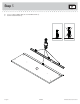
Look for this icon. It means a video assembly tip is available at www.sauder.com/services/tips Step 1 å Assemble your unit on a carpeted floor or on the empty carton to avoid scratching your unit or the floor. å To begin assembly, push a SAUDER TWIST-LOCK® FASTENER (Z) into the large holes in the ENDS (A2 and B2). å Repeat this step for the BOTTOM (D) and SHELF (E). Scan this QR code or go to this address: http://qr.sauder.com/?ID=1610 to watch a video on how to assemble your unit.
Step 2 å Push seven HIDDEN CAMS (AA2) into the BOTTOM (D), SHELF (E), and DRAWER BRACE (M65). Then, insert the metal end of three CAM DOWELS (CC2) into the HIDDEN CAMS in the SHELF (E). Arrow AA2 CC2 Do not tighten the HIDDEN CAMS in this step. E Arrow D M65 Insert the metal end of the CAM DOWEL into the HIDDEN CAM. Arrow AA2 Arrow Hole The arrow in the HIDDEN CAM must point toward the hole in the edge of the board. www.sauder.
Step 3 å Turn four CAM SCREWS (BB2) into the DRAWER FRONT (J) and BOTTOM MOLDING (P). BB2 P J Page 8 411843 www.sauder.
Step 4 å Tap two MOLDING CONNECTORS (JJ) into the notches in the MOLDINGS (N, Q, and R). Just think. The sooner you do this, the sooner you do something else. Use your hammer to tap the MOLDING CONNECTORS (JJ) into the notches in the MOLDINGS. Flat end Flat end JJ JJ R Q N www.sauder.
Step 5 å Fasten the MOLDINGS (N, Q, and R) to the TOP (C2). Use seven BLACK 1-1/4" FLAT HEAD SCREWS (RR). å å NOTE: Do not overtighten the SCREWS into the TOP. Push a DOOR STOP (LL) into the hole in the FRONT MOLDING (N). RR Q BLACK 1-1/4" FLAT HEAD SCREW (7 used in this step) C2 N R LL Rounded edge Page 10 411843 www.sauder.
Step 6 VIEW THE DRAWER GLIDE VIDEO å Fasten the UNIVERSAL CABINET RAILS* (40DA) to the ENDS (A2 and B2). Use four GOLD 5/16" FLAT HEAD SCREWS (3S) through holes #1 and #4. å Fasten the ROD HANGERS (KK) to the ENDS (A2 and B2). Use two BLACK 9/16" LARGE HEAD SCREWS (UU).
Step 7 å Fasten the LEFT END (B2) to the LEFT MOLDING (R) on the TOP (C2). Tighten two TWIST-LOCK® FASTENERS. How to use the SAUDER TWIST-LOCK® FASTENER 1. Insert the dowel end of the FASTENER into the hole of the adjoining part. NOTE: The dowel end of the FASTENER must remain fully inserted in the hole of the adjoining part while locking the FASTENER. 2. Tighten the FASTENER with a Phillips screwdriver as tight as possible. Dowel end Caution Do not stand the unit upright without the BACK fastened.
Step 8 å Fasten the BOTTOM (D) and SHELF (E) to the LEFT END (B2). Tighten four TWIST-LOCK® FASTENERS. Edge with holes B2 Edge with CAM DOWELS Su TWrface FA IST- with ST LO EN CK ER ® S Su TWrface FA IST- with ST LO EN CK ER ® S E D www.sauder.
Step 9 å Fasten the RIGHT END (A2) to the BOTTOM (D), SHELF (E), and RIGHT MOLDING (Q) on the TOP (C2). Tighten six TWIST-LOCK® FASTENERS. Don't worry. It isn't Rome. This can be built in a day. C2 E A2 Q D Edge with TWIST-LOCK® FASTENER Page 14 411843 www.sauder.
Step 10 å Fasten the SHELF MOLDING (O) to the SHELF (E). Tighten three HIDDEN CAMS. å Fasten the BOTTOM MOLDING (P) to the BOTTOM (D). Tighten three HIDDEN CAMS. å Push a DOOR STOP (LL) into the hole in the SHELF (E). LL Curved edge O P E D Caution Risk of damage or injury. HIDDEN CAMS must be completely tightened. HIDDEN CAMS that are not completely tightened may loosen, and parts may separate. To completely tighten: www.sauder.
Step 11 å Fasten five METAL BRACKETS (FF) to the BOTTOM (D). Use five BLACK 9/16" LARGE HEAD SCREWS (UU). å Fasten the PLINTHS (R2) to the ENDS (A2 and B2) and BOTTOM (D). Tighten two TWIST-LOCK® FASTENERS and use two BLACK 9/16" LARGE HEAD SCREWS (UU). å Fasten the SKIRT (H) to the BOTTOM (D). Use three BLACK 9/16" LARGE HEAD SCREWS (UU). Curved edge B2 R2 H A2 R2 D FF Curved edge UU BLACK 9/16" LARGE HEAD SCREW (10 used for the METAL BRACKETS Page 16 411843 www.sauder.
Step 12 å Carefully turn your unit over onto its front edges. Unfold the BACK (F2) and lay it over your unit. å Make equal margins along all four edges of the BACK (F2). Push on opposite corners of your unit if needed to make it "square". å å Fasten the BACK (F2) to your unit using the NAILS (XX). å Fasten the TIE PLATES (GG) to the SKIRT (H) and PLINTHS (R2). Use four BLACK 9/16" LARGE HEAD SCREWS (UU). Caution Do not stand the unit upright without the BACK fastened. The unit may collapse.
Step 13 å Fasten the HINGES (DD) to the DOORS (G). Use twelve BLACK 1/2" FLAT HEAD SCREWS (VV). DD G G DD VV BLACK 1/2" FLAT HEAD SCREW (12 used in this step) Page 18 411843 www.sauder.
Step 14 å å Carefully stand your unit upright. å Fasten a DOOR (G) to the RIGHT END (A2). Use the screws in the HINGES. See the next step for door adjustments. å Fasten a KNOB (MM) to the DOOR (G). Use a BLACK 1-1/8" MACHINE SCREW (SS). å Repeat this step for the other DOOR (G). Pro Tip: Lift with your legs. And, you know, your arms. Before fastening the DOOR to your unit, be sure the mounting screw is against the stops as shown in the diagram.
Step 15 å Refer to the enlarged diagram to identify the parts on the HINGES. å The DOORS may need some adjustments. Follow the text below to make needed adjustments. å DOOR ADJUSTMENTS: To adjust the DOORS from side to side (horizontal), turn the adjusting screw in or out. å To adjust the DOORS up and down (vertical), loosen both vertical adjustment screws. Move the DOORS up or down to the desired location. Tighten the screws after making adjustments.
Step 16 å Fasten the MOLDINGS (S) to the DRAWER FRONT (J). Use four BLACK 1-1/4" FLAT HEAD SCREWS (RR). å NOTE: There are no pre-drilled holes in the MOLDINGS. The SCREWS will tighten into the grooves. RR BLACK 1-1/4" FLAT HEAD SCREW (4 used in this step) J S Groove S www.sauder.
Step 17 VIEW THE T-SLOT BOX VIDEO å Pull the DRAWER FRONT BRACKETS (NN and OO) apart and slide them into the grooves in the DRAWER SIDES (D260 and D263). You may need to gently tap them in with a hammer. å NOTE: Slide the DRAWER FRONT BRACKETS (OO) into the groove first. The DRAWER FRONT BRACKETS are marked "RH" and "LH" for easy identification. å Fasten the DRAWER FRONT (J) to the DRAWER FRONT BRACKETS (NN and OO). Use four BLACK 9/16" LARGE HEAD SCREWS (UU).
Step 18 VIEW THE T-SLOT BOX VIDEO å Fasten the DRAWER BRACE (M65) to the DRAWER FRONT (J). Tighten one HIDDEN CAM. å Fasten the DRAWER BACK (D261) to the DRAWER SIDES (D260 and D263) and DRAWER BRACE (M65). Use five BLACK 1-9/16" FLAT HEAD SCREWS (30S). 1 M65 Start each screw a few turns before completely tightening any of them. Surface with HIDDEN CAM 30S J BLACK 1-9/16" FLAT HEAD SCREW (5 used in this step) 2 1 2 D261 D260 M65 Be sure the DRAWER BOTTOM inserts into the DRAWER BACK groove.
Step 19 VIEW THE DRAWER GLIDE VIDEO å Fasten the DRAWER RIGHT (40DC) and DRAWER LEFT (40DD) to the DRAWER SIDES (D260 and D263). Use four GOLD 5/16" FLAT HEAD SCREWS (3S) through holes #1 and #2. å å NOTE: The glides are not intended to rotate. Fasten two KNOBS (MM) to the DRAWER FRONT (J). Use two GOLD 1" MACHINE SCREWS (TT).
Step 20 å Apply the WARNING LABEL (11L) to the DRAWER BOTTOM (D996). You should be able to read the label when the drawer is open. When the drawer is closed, it will hide the label. Peel off the backing and apply the label as shown in the diagram. å NOTE: This is a permanent label intended to last for the life of the product. Once applied, do not try to remove it. 11L D996 10/16 WARNING AVERTISSEMENT ADVERTENCIA Serious or fatal crushing injuries can occur from furniture tipover.
Step 21 å å We recommend using the SAFETY STRAP (60M) for added stability. å INSTALLATION INSTRUCTIONS: (Also available at www.yl-anchors.com) 1. Insert the SAFETY DRYWALL ANCHOR (61M) through the WASHER (13M) and one end of the SAFETY STRAP (60M). 2. Using a Phillips screwdriver or a hand drill, press the screw slightly onto the drywall. 3. Apply pressure; turn the screw until a pilot hole is made and the nylon sheath slips through. 4.
Step 22 å To insert the drawer into your unit, tip the front of the drawer down and drop the glides on the drawer behind the glides on the unit. Lift the front of the drawer up and slide it into the unit. å To make adjustments to the drawer, loosen the SCREWS in the DRAWER FRONT BRACKETS, make needed adjustments, and tighten the SCREWS. å å å Set the ROD (Y) onto the ROD HANGERS on the ENDS (A2 and B2). NOTE: Please read the back pages of the instruction booklet for important safety information.
Modèle 411843 Utilisez les instructions d’assemblage en français avec les schémas étape par étape du manuel d’instruction en anglais. Chaque étape en français correspond à la même étape en anglais. La pièce devant être attachée à l’élément est représentée en gris sur les schémas de chaque étape pour plus de précision. Comparer la “Liste de pièces” ci-dessous avec la “PART IDENTIFICATION” du manuel en anglais pour vous familiariser avec les pièces avant l’assemblage.
ÉTAPE 1 ÉTAPE 6 REMARQUE : Ne pas serrer les FIXATIONS TWIST-LOCK® à ce stade de l'assemblage. Fije los RIELES UNIVERSALES DE GABINETE* (40DA) a los EXTREMOS (A2 y B2). Utiliser quatre VIS DORÉES TÊTE PLATE 8 mm (3S) à travers les trous nº 1 et nº 4. Assembler l'élément sur un sol à moquette ou sur le carton vide pour éviter d'endommager l'élément ou le sol. Pour commencer l'assemblage, enfoncer une FIXATION TWIST-LOCK® SAUDER (Z) dans les gros trous des EXTRÉMITÉS (A2 et B2).
ÉTAPE 10 ÉTAPE 14 Fixer la MOULURE DE TABLETTE (O) à la TABLETTE (E). Serrer trois EXCENTRIQUES ESCAMOTABLES. Relever, avec précaution, l'élément dans sa position verticale. Fixer la MOULURE DE DESSOUS (P) au DESSOUS (D). Serrer trois EXCENTRIQUES ESCAMOTABLES. Enfoncer un ARRÊT DE PORTE (LL) dans le trou de la TABLETTE (E). Attention: Risque des dégâts ou blessures. Les Excentriques Escamotables doivent être serrés à bloc.
ÉTAPE 17 ÉTAPE 21 Séparer les CONSOLES DE DEVANT DE TIROIR (NN et OO) et les enfiler dans les rainures des CÔTÉS DE TIROIR (D260 et D263). Il est peut-être nécessaire de les enfoncer délicatement à l'aide d'un marteau. Il est recommandé d’utiliser la SANGLE DE SÉCURITÉ (60M) pour stabilité additionnelle. REMARQUE : Tout d'abord, enfiler les CONSOLES DE DEVANT DE TIROIR (OO) dans la rainure.
Modelo 411843 Use estas instrucciones de ensamblaje en español junto con las figuras paso-a-paso provistas en el folleto inglés. Cada paso en español corresponde al mismo paso en inglés. Se destacan las figuras de cada paso con una tonalidad oscura para mostrar precisamente cual parte se debe montar a la unidad. Compare la “Lista de Part” abajo con la “Part Identification” en el folleto en inglés para familiarizarse con Las partes de ensamblaje.
PASO 1 PASO 7 NOTA: No apriete los SUJETADORES TWIST-LOCK® por ahora. Precaución: No coloque la unidad en posición vertical hasta que se fije el DORSO. La unidad podría caerse. Ensamble la unidad sobre un piso alfombrado o sobre el cartón vacío para evitar rayar la unidad o el piso. Para comenzar el ensamblaje, empuje un SUJETADOR TWIST-LOCK® SAUDER (Z) dentro de los agujeros grandes de los EXTREMOS (A2 y B2). Cómo utilizar el SUJETADOR TWIST-LOCK® SAUDER 1.
PASO 11 PASO 15 Fije cinco SOPORTES DE METAL (FF) al FONDO (D). Utilice cinco TORNILLOS NEGROS DE CABEZA GRANDE de 14 mm (UU). Consulte el diagrama ampliado para identificar las piezas de las BISAGRAS. Fije las BASES (R2) a los EXTREMOS (A2 y B2) y al FONDO (D). Apriete dos SUJETADORES TWIST-LOCK® y utilice dos TORNILLOS NEGROS DE CABEZA GRANDE de 14 mm (UU). Las PUERTAS pueden requerir de ajustes. Siga el texto abajo para hacer los ajustes necesarios. Fije el FALDÓN (H) al FONDO (D).
PASO 18 PASO 21 Fije la RIOSTRA DE CAJÓN (M65) a la CARA DE CAJÓN (J). Apriete un EXCÉNTRICO ESCONDIDO. Se recomienda utilizar la CORREA DE SEGURIDAD (60M) para mayor estabilidad. Fije el DORSO DE CAJÓN (D261) a los LADOS DE CAJÓN (D260 y D263) y a la RIOSTRA DE CAJÓN (M65) . Utilice cinco TORNILLOS NEGROS DE CABEZA PERDIDA de 40 mm (30S). NOTA: No gire el ANCLAJE DE SEGURIDAD PARA EL DRYWALL (61M) en un montante de la pared.
WARNING Please use your furniture correctly and safely. Improper use can cause safety hazards, or damage to your furniture or household items. Carefully read the following chart. Look out for: What can happen: How to avoid the problem: • Overloaded dresser drawers and shelves. • Risk of injury. • Top-heavy furniture can tip over. • Overloaded drawers and shelves can break. • Never exceed the weight limits shown in the instructions. • Work from bottom to top when loading shelves and drawers.
AVERTISSEMENT Prière d’utiliser le mobilier à bon escient et avec prudence. Une mauvaise utilisation peut être à l’origine de risques d’accident ou peut endommager le mobilier et les articles ménagers. Lire attentivement le tableau suivant. À surveiller : Danger éventuel : Solution : • Tiroirs et tablettes de commodes surchargées. • Risque de blessure. • Du mobilier mal équilibré risque de se renverser. • Des tiroirs et tablettes surchargées peuvent casser.
ADVERTENCIA Por favor use el mobiliario correcta y seguramente. El mal uso puede causar riesgos de seguridad o daño a las unidades o artículos domésticos. Cuidadosamente lea la tabla a continuación. Esté alerto de: Puede ocurrir: Evitar el problema: • Cajones y estantes sobrecargados. • Un riesgo de lesiones. • El mobiliario inestable puede volcarse. • Los cajones o estantes sobrecargados pueden romperse. • Nunca exceder los límites de peso indicados en las instrucciones.
5-YEAR LIMITED WARRANTY 1. Sauder Woodworking Co. (Sauder®) provides limited warranty coverage to the original purchaser of this product for a period of five years from the date of purchase against defects in materials or workmanship of Sauder furniture components. As used in this Warranty, “defect” means imperfections in components which substantially impair the utility of the product. This Warranty gives you specific legal rights, and you may also have other rights which vary from state to state. 2.
Dear Valued Customer: So, how did it go? Thanks so much for choosing Sauder® furniture. I hope the purchase and assembly process was a positive experience and you feel good about the furniture you just built. If you need assistance or want to learn more, please contact our award-winning, Ohio-based customer service team at 800-523-3987 or Sauder.com. Set a world record for speed? Feeling good about yourself? Nice. Get social with it on any of these quality share sites.