sauder.com Yes, you still have to dress yourself. Dresser Harbor View Collection | 414942 NOTE: THIS INSTRUCTION BOOKLET CONTAINS IMPORTANT SAFETY INFORMATION. Need help? Visit Sauder.com to view video assembly tips or chat with a live rep. Prefer the phone? Call 1-800-523-3987. Share your journey! PLEASE READ AND KEEP FOR FUTURE REFERENCE. English pg 1-27 Français pg 28-31 Español pg 32-35 Lot # 372063 04/23/15 Purchased: __________________ Be sure to give us a ring before making any returns.
Table of Contents Part Identification Assembly Tools Required 2-3 Hardware Identification No. 2 Phillips Screwdriver Tip Shown Actual Size 4 Assembly Steps 5-27 Hammer Français 28-31 Español 32-35 Safety 36-38 Warranty Not actual size Skip the power trip. This time. 39 Part Identification å While not all parts are labeled, some of the parts will have a label or an inked letter on the edge to help distinguish similar parts from each other.
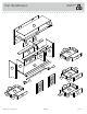
Now you know our ABCs. Part Identification R F2 Q S Z I X2 Z E H V J A D945 C2 D25 M M67 J G D2 D24 D170 T B Y D12 D166 U D974 O D13 D30 D167 L D24 D170 M67 K Y D974 D945 P N D25 D31 M67 M67 www.sauder.
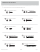
Hardware Identification å Screws are shown actual size. You may receive extra hardware with your unit.
Hardware Identification å Screws are shown actual size. You may receive extra hardware with your unit. 1S BLACK 9/16" LARGE HEAD SCREW - 1 2S BLACK 1-7/8" FLAT HEAD SCREW - 14 3S GOLD 5/16" FLAT HEAD SCREW - 32 9S BLACK 1-1/8" PAN HEAD SCREW - 6 11S BLACK 1/2" FLAT HEAD SCREW - 8 20S SILVER 3/4" MACHINE SCREW - 8 27S BLACK 1-5/8" PAN HEAD SCREW - 8 30S BLACK 1-9/16" FLAT HEAD SCREW - 20 50S GOLD 1" MACHINE SCREW - 6 www.sauder.
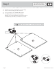
Look for this icon. It means a video assembly tip is available at www.sauder.com/services/tips Step 1 å Assemble your unit on a carpeted floor or on the empty carton to avoid scratching your unit or the floor. å To begin assembly, push a SAUDER TWIST-LOCK® FASTENER (10F) into the large holes in the RIGHT UPRIGHT (C2) and LEFT UPRIGHT (D2). Repeat this step for the UPRIGHT (E), BOTTOM (G), and BRACES (H and X2). Do not tighten the TWIST-LOCK® FASTENERS in this step.
Step 2 å Push twelve HIDDEN CAMS (1F) into the ENDS (A and B), BACK UPRIGHTS (Z), and DRAWER BRACES (M67). Then, insert the metal end of a CAM DOWEL (2F) into each HIDDEN CAM. Do not tighten the HIDDEN CAMS in this step. Z Z M67 M67 M67 M67 B Arrow A Insert the metal end of the CAM DOWEL into the HIDDEN CAM. Arrow 1F (12 used) 2F www.sauder.
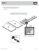
Step 3 å Fasten a CABINET RIGHT (35GA) to the RIGHT END (A) and a CABINET LEFT (35GB) to the LEFT END (B). Use four GOLD 5/16" FLAT HEAD SCREWS (3S) through holes #1 and #3. Remember: Righty tighty. Lefty loosey. Roller end 1 2 3 Finished edge 3 A 2 S H urf ID a D ce E w N i C th A M S Roller end 1 S H urf ID a D ce E w N i C th A M S B Finished edge 3S GOLD 5/16" FLAT HEAD SCREW (4 used in this step) Page 8 414942 www.sauder.
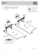
Step 4 å Fasten the CABINET RIGHTS (35GA) to the RIGHT UPRIGHT (C2) and UPRIGHT (E) and the CABINET LEFTS (35GB) to the LEFT UPRIGHT (D2) and other surface of the UPRIGHT (E). Use twelve GOLD 5/16" FLAT HEAD SCREWS (3S) through holes #1 and #3.
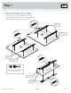
Step 5 å Fasten the UPRIGHTS (C2 and D2) to the BRACES (H and X2). Tighten four TWIST-LOCK® FASTENERS. How to use the SAUDER TWIST-LOCK® FASTENER 1. Insert the dowel end of the FASTENER into the hole of the adjoining part. NOTE: The dowel end of the FASTENER must remain fully inserted in the hole of the adjoining part while locking the FASTENER. 2. Tighten the FASTENER with a Phillips screwdriver as tight as possible.
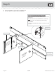
Step 6 å å Insert two METAL PINS (1R) into the BRACES (H and X2). å NOTE: Be sure the METAL PINS in the BRACES (H and X2) insert into the holes in the LEFT END (B). å Fasten the BOTTOM (G) to the LEFT END (B). Tighten two TWIST-LOCK® FASTENERS. å Then, fasten the BOTTOM (G) to the UPRIGHTS (C2 and D2). Use four BLACK 1-7/8" FLAT HEAD SCREWS (2S). Caution Fasten the LEFT END (B) to the BRACES (H and X2). Tighten two TWIST-LOCK® FASTENERS. Do not stand the unit upright without the BACK fastened.
Step 7 å å Insert two METAL PINS (1R) into the BRACES (H and X2). å NOTE: Be sure the METAL PINS in the BRACES (H and X2) insert into the holes in the RIGHT END (A). Fasten the RIGHT END (A) to the BOTTOM (G) and BRACES (H and X2). Tighten four TWIST-LOCK® FASTENERS. 1R H Finished edge G X2 A ut itho S w e fac AM Sur DEN C HID Page 12 414942 www.sauder.
Step 8 å Fasten the BRACE MOLDING (V) to the FRONT BRACE (H). Tighten four TWIST-LOCK® FASTENERS. å Fasten the UPRIGHT (E) to the BRACES (H and X2). Use two BLACK 1-7/8" FLAT HEAD SCREWS (2S). Hey! It's starting to look like something! Surface with TWIST-LOCK® FASTENERS Finished edge V E H X2 2S BLACK 1-7/8" FLAT HEAD SCREW (2 used in this step) www.sauder.
Step 9 å Tap two MOLDING CONNECTORS (16F) into the notches in the MOLDINGS (Q, R, and S). å Fasten the MOLDINGS (Q, R, and S) to the TOP (F2). Use eight BLACK 1-5/8" PAN HEAD SCREWS (27S). å NOTE: Do not overtighten the SCREWS into the TOP. Use your hammer to tap the MOLDING CONNECTORS (16F) into the notches in the MOLDINGS. Flat end Flat end 16F 16F S Q R R 27S BLACK 1-5/8" PAN HEAD SCREW (8 used in this step) Do not overtighten the SCREWS (27S).
Step 10 å Fasten the ENDS (A and B) to the MOLDINGS (R and S) on the TOP (F2). Tighten four HIDDEN CAMS. å NOTE: Be sure the dowel ends of the TWIST-LOCK® FASTENERS in the UPRIGHT (E) insert into the holes in the TOP (F2). å Then, fasten the TOP (F2) to the UPRIGHT (E). Tighten two TWIST-LOCK® FASTENERS. S Rounded edge B E F2 Su witrface hh ole s R A Caution Risk of damage or injury. HIDDEN CAMS must be completely tightened.
Step 11 å å å å First, fasten the SKIRT (U) to the BOTTOM MOLDING (T). Use three BLACK 1-7/8" FLAT HEAD SCREWS (2S). å NOTE: Do not overtighten the FOOT SCREWS. Then, fasten the BOTTOM MOLDING (T) to the BOTTOM (G). Use six BLACK 1-1/8" PAN HEAD SCREWS (9S). Carefully turn two FOOT SCREWS (23F) a few turns into the BOTTOM MOLDING (T). Next, turn a FOOT (Y) onto the other end of each FOOT SCREW (23F). Turn the FEET clockwise until the FOOT SCREW is tight in the BOTTOM MOLDING (T) and each FOOT.
Step 12 å å Carefully turn your unit over onto its front edges. å NOTE: You have to tilt the BACK UPRIGHTS to insert the CAM DOWELS in the edges of the BACK UPRIGHTS into the holes in the TOP. å Fasten the BACK UPRIGHTS (Z) to the BACK BRACE (X2). Use four BLACK 1-7/8" FLAT HEAD SCREWS (2S). Maximum 210 degrees Fasten the BACK UPRIGHTS (Z) to the TOP (F2). Tighten four HIDDEN CAMS.
Step 13 å Fasten the BACKS (J) to the UPRIGHTS (C2 and D2). Use eight BLACK 1-15/16" FLAT HEAD SCREWS (113S). 113S BLACK 1-15/16" FLAT HEAD SCREW (8 used in this step) D2 J J C2 Page 18 414942 www.sauder.
Step 14 å å Unfold the BACK (I) and lay it over your unit. å å Fasten the BACK (I) to your unit using the NAILS (1N). å NOTE: Perforations have been provided for access through the BACK. Carefully cut out the holes needed. Caution Make equal margins along all four edges of the BACK (I). Push on opposite corners of your unit if needed to make it "square". Do not stand the unit upright without the BACK fastened. The unit may collapse.
Step 15 å Fasten two HINGES (13H) to each DOOR (K and L). Use eight BLACK 1/2" FLAT HEAD SCREWS (11S). Don't worry. It isn't Rome. This can be built in a day. 11S BLACK 1/2" FLAT HEAD SCREW (8 used in this step) 13H L K 13H Page 20 414942 www.sauder.
Step 16 å å Carefully stand your unit upright. å Fasten the LEFT DOOR (L) to the LEFT END (B). Use the screws in the HINGES. See the next step for adjustments. å Fasten a KNOB (5K) to the LEFT DOOR (L). Use a GOLD 1" MACHINE SCREW (50S). å Peel a FELT DISC from the FELT DISC CARD (1M) and stick it on the DOOR where it comes in contact with the LEFT UPRIGHT (D2). å Repeat this step for the other door. Pro Tip: Lift with your legs. And, you know, your arms.
Step 17 å Refer to the enlarged diagram to identify the parts on the HINGES. å The DOORS may need some adjustments. Follow the text below to make needed adjustments. å DOOR ADJUSTMENTS: To adjust the DOORS from side to side (horizontal), loosen the mounting screw several turns, then turn the adjusting screw in or out. Tighten the mounting screw after making adjustments. å To adjust the DOORS up and down (vertical), loosen both vertical adjustment screws.
Step 18 VIEW THE T-LOCK BOX VIDEO The tabs should insert freely into the slots. Gently tilt the DRAWER SIDES side to side until the tabs slip into the slots. 1 With the palm of your hand, tap the DRAWER BOTTOM down into the groove. 2 Un fi su nish rfa ed ce D974 D30 D30 P D31 P Be sure the DRAWER BOTTOM inserts into the DRAWER FRONT groove. Groove å D31 Insert the LOWER DRAWER SIDES (D30 and D31) at an angle into the slot at each end of the LOWER DRAWER FRONT (P).
Step 19 å Insert a SLIDE CAM (10A) into the LOWER DRAWER SIDES (D30 and D31). å Fasten a DRAWER RIGHT (35GC) to the LOWER RIGHT DRAWER SIDE (D30) and a DRAWER LEFT (35GD) to the LOWER LEFT DRAWER SIDE (D31). Use four GOLD 5/16" FLAT HEAD SCREWS (3S) through holes #1 and #3. å NOTE: The screw head in the CAM must be visible through the slotted hole in the SLIDE. å Repeat this step for the other drawers.
Step 20 å Fasten two KNOBS (5K) to the LEFT DRAWER FRONT (N). Use two GOLD 1" MACHINE SCREWS (50S). Repeat this step for the RIGHT DRAWER FRONT (M). å Fasten two PULLS (98K) to the LOWER DRAWER FRONT (P). Use four SILVER 3/4" MACHINE SCREWS (20S). Repeat this step for the UPPER DRAWER FRONT (O). 50S GOLD 1" MACHINE SCREW (4 used for the KNOBS) N 5K 20S SILVER 3/4" MACHINE SCREW (8 used for the PULLS) P 98K www.sauder.
Step 21 å To insert the drawers into your unit, tip the front of the drawers down and drop the rollers on the drawers behind the rollers on the unit. Lift the front of the drawers up and slide them into the unit. å We recommend using the SAFETY BRACKET (1G) for added stability. Use a BLACK 9/16" LARGE HEAD SCREW (1S) into the top of the unit and a BLACK 1-7/8" FLAT HEAD SCREW (2S) into a stud in your wall. å Apply the WARNING LABEL (5L) to the upper LEFT DRAWER SIDE (D25).
Step 22 å To make adjustments to the drawers, loosen SCREW #3 in the SLIDES a 1/4 turn, then turn the CAM clockwise or counter-clockwise. Notice how the drawer raises or lowers as you turn the CAM. The higher the screw in the oblong hole, the higher your drawer front will be. The lower the screw, the lower the drawer front. By adjusting the drawers this way, it will help the DRAWER FRONTS line up better when closed. Tighten the SCREW when finished with adjustments.
414942 Utilisez les instructions d’assemblage en français avec les schémas étape par étape du manuel d’instruction en anglais. Chaque étape en français correspond à la même étape en anglais. La pièce devant être attachée à l’élément est représentée en gris sur les schémas de chaque étape pour plus de précision. Comparer la “Liste de pièces” ci-dessous avec la “PART IDENTIFICATION” du manuel en anglais pour vous familiariser avec les pièces avant l’assemblage.
ÉTAPE 1 ÉTAPE 6 Ne pas serrer les FIXATIONS TWIST-LOCK® à cette étape. Attention: Ne pas relever l'élément dans sa position verticale avant d'avoir fixé l’ARRIÈRE. L'élément risque de s'effondrer. Assembler l'élément sur un sol à moquette ou sur le carton vide pour éviter d'endommager l'élément ou le sol. Pour commencer l'assemblage, enfoncer une FIXATION TWIST-LOCK® SAUDER (10F) dans les gros trous du MONTANT DROIT (C2) et du MONTANT GAUCHE (D2).
ÉTAPE 10 ÉTAPE 14 Fixer les EXTRÉMITÉS (A et B) aux MOULURES (R et S) et au DESSUS (F2). Serrer quatre EXCENTRIQUES ESCAMOTABLES. Attention: Ne pas relever l'élément dans sa position verticale avant d'avoir fixé l’ARRIÈRE. L'élément risque de s'effondrer. REMARQUE : S’assurer que l’extrémité à cheville des FIXATIONS TWIST-LOCK® du MONTANT (E) sont insérées dans les trous du DESSUS (F2). Déplier l'ARRIÈRE (I) et le placer sur l'élément. Ensuite fixer le DESSUS (F2) au MONTANT (E).
ÉTAPE 17 ÉTAPE 20 Consulter le schéma agrandi pour identifier les pièces des CHARNIÈRES. Fixer deux BOUTONS (5K) au DEVANT DE TIROIR GAUCHE (N). Utiliser deux VIS À MÉTAUX 25 mm DORÉES (50S). Répéter cette étape pour le DEVANT DE TIROIR DROIT (M). Il faut peut-être ajuster les PORTES. Suivre les indications ci-dessous pour ajuster.
414942 Use estas instrucciones de ensamblaje en español junto con las figuras paso-a-paso provistas en el folleto inglés. Cada paso en español corresponde al mismo paso en inglés. Se destacan las figuras de cada paso con una tonalidad oscura para mostrar precisamente cual parte se debe montar a la unidad. Compare la “Lista de Part” abajo con la “Part Identification” en el folleto en inglés para familiarizarse con Las partes de ensamblaje.
PASO 1 PASO 6 No apriete los SUJETADORES TWIST-LOCK® en este paso. Precaución: No coloque la unidad en posición vertical hasta que se fije el DORSO. La unidad podría caerse. Ensamble la unidad sobre un piso alfombrado o sobre el cartón vacío para evitar rayar la unidad o el piso. Para comenzar el ensamblaje, empuje un SUJETADOR TWIST-LOCK® SAUDER (10F) dentro de los agujeros grandes del PARAL DERECHO (C2) y del PARAL IZQUIERDO (D2).
PASO 10 PASO 14 Fije los EXTREMOS (A y B) a las MOLDURAS (R y S) sobre el PANEL SUPERIOR (F2). Apriete cuatro EXCÉNTRICOS ESCONDIDOS. Precaución: No coloque la unidad en posición vertical hasta que se fije el DORSO. La unidad podría caerse. NOTA: Asegúrese de que los extremos de la clavija de los SUJETADORES TWIST-LOCK® en el PARAL (E) se inserta en los agujeros del PANEL SUPERIOR (F2). A continuación, fije el PANEL SUPERIOR (F2) al PARAL (E). Apriete dos SUJETADORES TWIST-LOCK®.
PASO 17 PASO 20 Consulte el diagrama ampliado para identificar las piezas de las BISAGRAS. Fije dos POMOS (5K) a la CARA IZQUIERDA DE CAJÓN (N). Utilice dos TORNILLOS DORADO PARA METAL de 25 mm (50S). Repita este paso para la CARA DERECHA DE CAJÓN (M). Las PUERTAS pueden requerir de ajustes. Siga el texto abajo para hacer los ajustes necesarios.
WARNING Please use your furniture correctly and safely. Improper use can cause safety hazards, or damage to your furniture or household items. Carefully read the following chart. Look out for: What can happen: How to avoid the problem: • Overloaded dresser drawers and shelves. • Risk of injury. • Top-heavy furniture can tip over. • Overloaded drawers and shelves can break. • Never exceed the weight limits shown in the instructions. • Work from the bottom to the top when loading shelves and drawers.
AVERTISSEMENT Prière d’utiliser le mobilier à bon escient et avec prudence. Une mauvaise utilisation peut être à l’origine de risques d’accident ou peut endommager le mobilier et les articles ménagers. Lire attentivement le tableau suivant. À surveiller : Danger éventuel : Solution : • Tiroirs et tablettes de commodes surchargées. • Risque de blessure. • Du mobilier mal équilibré risque de se renverser. • Des tiroirs et tablettes surchargées peuvent casser.
ADVERTENCIA Por favor use el mobiliario correcta y seguramente. El mal uso puede causar riesgos de seguridad o daño a las unidades o artículos domésticos. Cuidadosamente lea la tabla a continuación. Esté alerto de: Puede ocurrir: Evitar el problema: • Cajones y estantes de cómoda sobrecargados. • Riesgo de lesiones. • El mobiliario inestable puede volcarse. • Los cajones y estantes sobrecargados pueden romperse. • Nunca exceda los límites de peso indicados en las instrucciones.
5-YEAR LIMITED WARRANTY 1. Sauder Woodworking Co. (Sauder®) provides limited warranty coverage to the original purchaser of this product for a period of five years from the date of purchase against defects in materials or workmanship of Sauder furniture components. As used in this Warranty, “defect” means imperfections in components which substantially impair the utility of the product. This Warranty gives you specific legal rights, and you may also have other rights which vary from state to state. 2.
Dear Valued Customer: So, how did it go? Thanks so much for choosing Sauder® furniture. I hope the purchase and assembly process was a positive experience and you feel good about the furniture you just built. If you need assistance or want to learn more, please contact our award-winning, Ohio-based customer service team at 800-523-3987 or Sauder.com. Set a world record for speed? Feeling good about yourself? Nice. Get social with it on any of these quality share sites.